
 Submit a Paper
 Propose a Special lssue
 Open Access
ARTICLE

Control of Distributed Generation Using Non-Sinusoidal Pulse Width Modulation
1 Department of Electrical Engineering, Jouybar Branch, Islamic Azad University, Jouybar, 4776186131, Iran
2 Renewable Energy Research Centre (RERC), Department of Teacher Training in Electrical Engineering, Faculty of Technical Education, King Mongkut’s University of Technology North Bangkok, 1518, Pracharat 1 Road, Bangsue, Bangkok, 10800, Thailand
3 Department of Electrical and Electronics Engineering, Faculty of Engineering and Architectures, Nisantasi University, Istanbul, 34398, Turkey
4 Department of Information Electronics, Fukuoka Institute of Technology, Fukuoka, 811-0295, Japan
* Corresponding Author: Mehrdad Ahmadi Kamarposhti. Email:
Computers, Materials & Continua 2023, 74(2), 4149-4164. https://doi.org/10.32604/cmc.2023.033405
Received 15 June 2022; Accepted 02 September 2022; Issue published 31 October 2022
 View Full Text
 Download PDF
Abstract
The islanded mode is one of the connection modes of the grid distributed generation resources. In this study, a distributed generation resource is connected to linear and nonlinear loads via a three-phase inverter where a control method needing no current sensors or compensator elements is applied to the distribute generation system in the islanded mode. This control method has two main loops in each phase. The first loop controls the voltage control loops that adjust the three-phase point of common coupling, the amplitude of the non-sinusoidal reference waveform and the near-state pulse width modulation (NSPWM) method. The next loop compensatesthe harmonic compensator loop that calculates the voltage harmonics of the point of common coupling in each phase, and injects them to compensate the non-sinusoidal reference waveforms of each phase. The simulation results in MATLAB/SIMULINK show that this method can generate balanced three-phase sinusoidal voltage with an acceptable total harmonic distortion (THD) at the joint connection point.Keywords
The order of a power system (generation, transmission, sub-transmission, and distribution) shows that power is unidirectional transmitted from the generation points to the distribution stations and ends at the consumers. Some consumers generate electricity using personal resources aiming to:
Supply their consumption loads
Support supplying critical loads in emergency conditions or on device interruption
These personal resources are called distributed generation (DG) resources. Therefore, DG generates electricity where the consumers require the whole or a part of the power. The power generated by the DG ranges from 1 kW to hundreds of kW. The DG resources include three main types based on the primary resource, the fossil fuel energy, renewable energy, and heat loss. The use of DG resources based on photovoltaic energy, wind, fuel cells, and micro-turbines are increasing due to limited storage of fossil fuels. Usually, in DG systems, issues like power factor correction, active and reactive power control, power quality improvement, controlling and reducing voltage harmonic at the point of common coupling (PCC) are raised.
In this paper, the DG systems controls are investigated based on single-phase and three-phase inverters. The DG systems are classified regarding their connection to the grid:
• Grid connected DGs: in this mode, the output of the DG resources is connected to the grid and supplies the grid.
• Stand-alone DGs: in this mode, the output of the DG resources is directly connected to the load and supplies a specific number of loads alone.
The joint connection point of the consumption loads or the output of the DG system inverters is called PCC. The purpose of inverter-based DGs is to remove the harmonics and sinusoidal of the PCC voltage as much as possible through proper control of the inverter. If the DG is in grid-connected mode, the quality and amplitude of the PCC voltage are determined by the grid. The grid will impose a steady sinusoidal voltage on the PCC, and regardless of the presence of non-linear loads, other linear loads will draw sinusoidal current in the PCC. Therefore, as long as the DG is in grid-connected mode, the nonlinear load does not affect the performance of linear loads at the PCC. However, if the DG is in the stand-alone mode and supplies the loads alone, the presence of nonlinear loads affects all loads connected to the PCC. The non-sinusoidal current drawn by the nonlinear loads generates a non-sinusoidal voltage at the PCC.
Considering the generation costs of large power plants, power transmission, and losses caused by long transmission lines, it is necessary to create local and distributed generation resources. A proper control system with low complexity and cost is necessary in DGs connected to power inverters. Many of the control methods used in DG inverters requires compensator transformers, passive filters and current sensors for effective control that increase the cost of the DG system, significantly. Therefore, the control methods that eliminate any of the mentioned elements or all of them are of great significance.
In [1–5], capability of DG in controlling active and reactive power and compensating power factor has been studied. In [6], the complete performance of a stand-along DG has been investigated. In [7], an inductor, L, and a resistor, r, are inserted between the inverter and the DG, and the protection of the DG system has been examined. In [8,9], the effect of non-sinusoidal voltage at the PCC on loads like transformers and capacitive banks has been studied. In [10–13], removing harmonics at the PCC using secondary winding of the transformer has been studied. In [14], a new method has been used to correct the voltage harmonics and compensate the unbalanced voltage. In [15–17], the space vector pulse width modulation (SVPWM) has been used to control the PCC of the DG system. In [18], a DG has achieved a sinusoidal voltage at the PCC using a single-phase inverter and a novel switching method.
In this paper, a stand-along DG is controlled by a three-phase inverter using the proposed switching method, and three balanced sinusoidal voltages are generated at the PCC. This DG is connected to various linear and nonlinear loads, and the nonlinear loads generate harmonics at the PCC. The proposed switching method is based on applying the nonlinear voltage generated at the line impedance using pulse width modulation (PWM) as a result of removing this voltage and achieving three-phase balanced sinusoidal voltages at the PCC. This method is simulated in MATLAB/SIMULINK. Finally, the simulation results are compared with previous methods. This method has the following properties:
• The proposed method requires no compensating element line compensating transformer or passive filter.
• The proposed method removes the harmonics of the PCC without using any current sensor.
• In addition to reducing THD, the proposed method limits all harmonic components to an acceptable level.
In the following, the proposed method is described in Section 2. Analysis of the results is reviewed in Section 3. Finally, Section 4 is presented conclusions and results.
2 Description of the Proposed Method
2.1 Analysis and Applying the Proposed Method to the Stand-Alone Single-Phase DG System
To better understand the proposed method, it is first analyzed as a single-phase system. Consider Fig. 1.
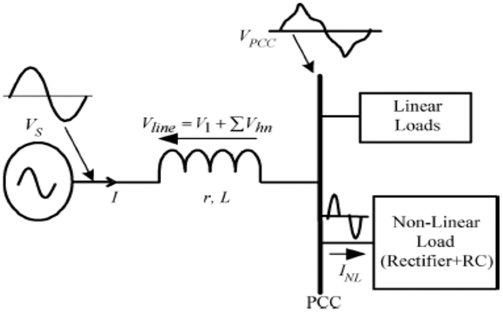
Figure 1: Connection of the DG resource and loads at the PCC
The voltage at PCC is:
The above relationship can be written as follows:
In which
If the second term on the left side of Eq. (4) is set to zero, the PCC voltage becomes sinusoidal. Therefore, Eq. (4) shows that the following condition should be met to achieve a sinusoidal voltage at the PCC:
In which:
To achieve a sinusoidal voltage at the PCC, the nth harmonic component at the PCC should be set to zero. Therefore, by sampling the harmonic components at the PCC, and generating and injecting similar components by the inverter, the harmonic components of the PCC might be reduced to zero. According to Eqs. (4) and (5), we have:
Eq. (7) shows that nonlinear voltage drop on the line impedance is compensated at the inverter side by comparing each harmonic component,
where
In which Kp and Ki are the proportional and integral constants of the PI controller, and Kn is the amplitude of the nth harmonic used in PWM method. The reference harmonic components in [9] for formation of the reference waveform in the SPWM for injecting the nonlinear voltage,
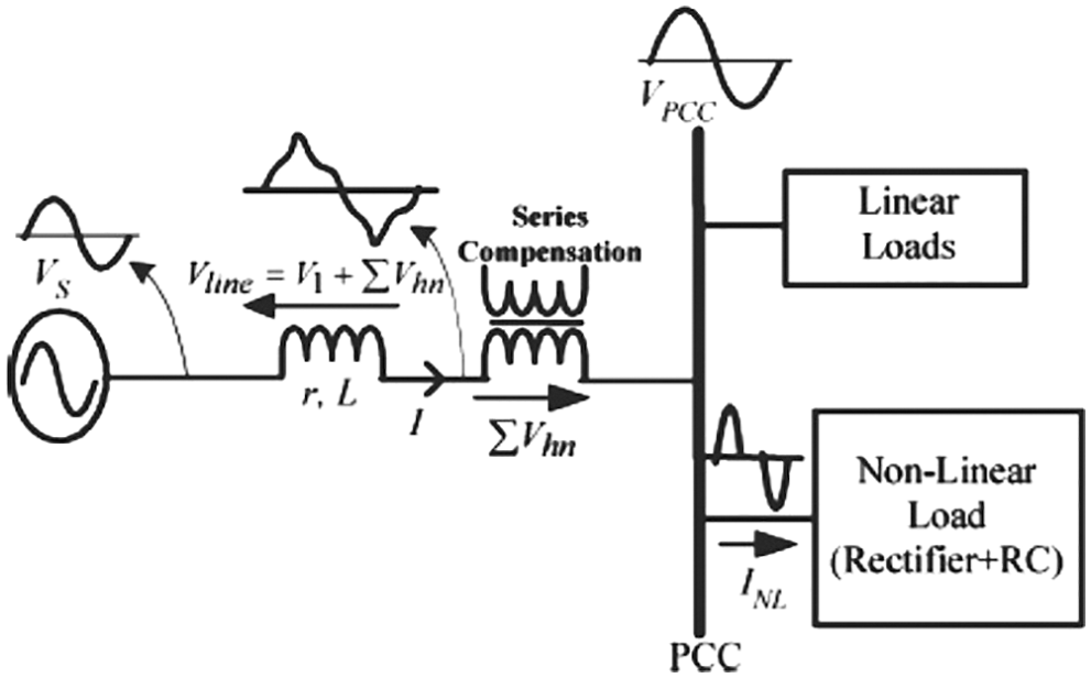
Figure 2: Series compensation for compensating the voltage drop on the line impedance
Therefore, the undesired harmonic components,
Fig. 3 shows an inverter in stand-alone mode that supplies the linear and nonlinear loads connected to the PCC. Since the nonlinear loads generate the nonlinear current,
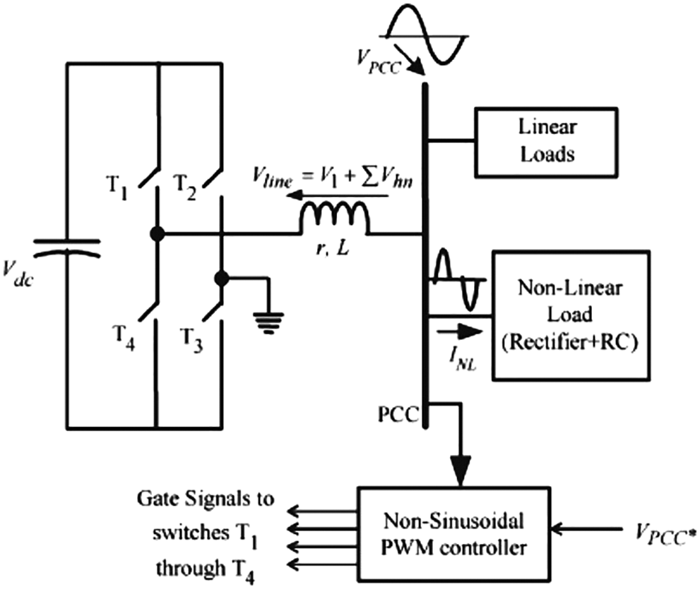
Figure 3: The single-phase DG system in stand-alone mode using the NSPWM control method
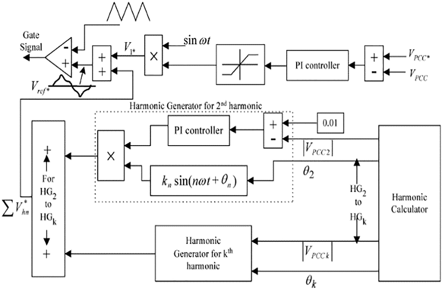
Figure 4: The method proposed for voltage regulation and harmonic compensation in the single-phase system
This control system has two main loops: 1. Voltage control loop, 2. Harmonic compensation loop. The voltage control loop adjusts the PCC voltage. The PI controller is used in this loop that controls the reference sinusoidal waveform amplitude and the modulation index in the PWM method. The sinusoidal reference waveform harmonic compensator with the available harmonic frequencies modulates the load current to generate the non-sinusoidal reference,
2.2 Applying the Proposed Method to Three-Phase DG System Based on Stand-Alone Inverter
Consider the DG system based on the inverter shown in Fig. 5. This system is in the stand-alone mode and the three-phase inverter should supply the linear and nonlinear loads at the PCC along. The purpose is to apply the control method presented in the previous section to the system shown in Fig. 2.
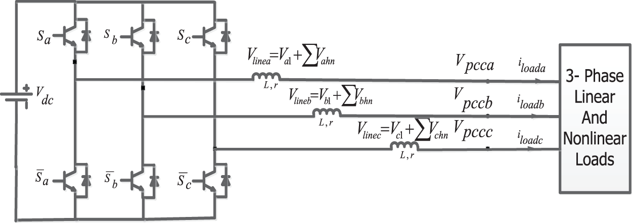
Figure 5: The three-phase DG system in stand-alone mode
The relationship among three voltages in a balanced three-phase system is as follows:
The PCC voltages shown in Fig. 5,
As mentioned in the previous section, if the harmonic generated on the impedance of each phase is the result of nonlinear currents passing each phase, is generated by the inverter, three voltages of the PCC would be completely sinusoidal. To this end, for switching each phase of the inverter, a non-sinusoidal wave including harmonics associated to the connection point of the same phase are generated. In the so-called three-phase NSPWM method, these sinusoidal waves are compared with a high-frequency carrier wave that switches off/on the switches
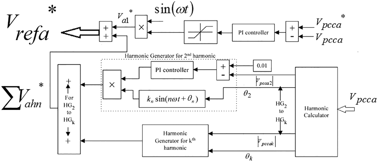
Figure 6: Obtaining the non-sinusoidal reference waveform of phase a
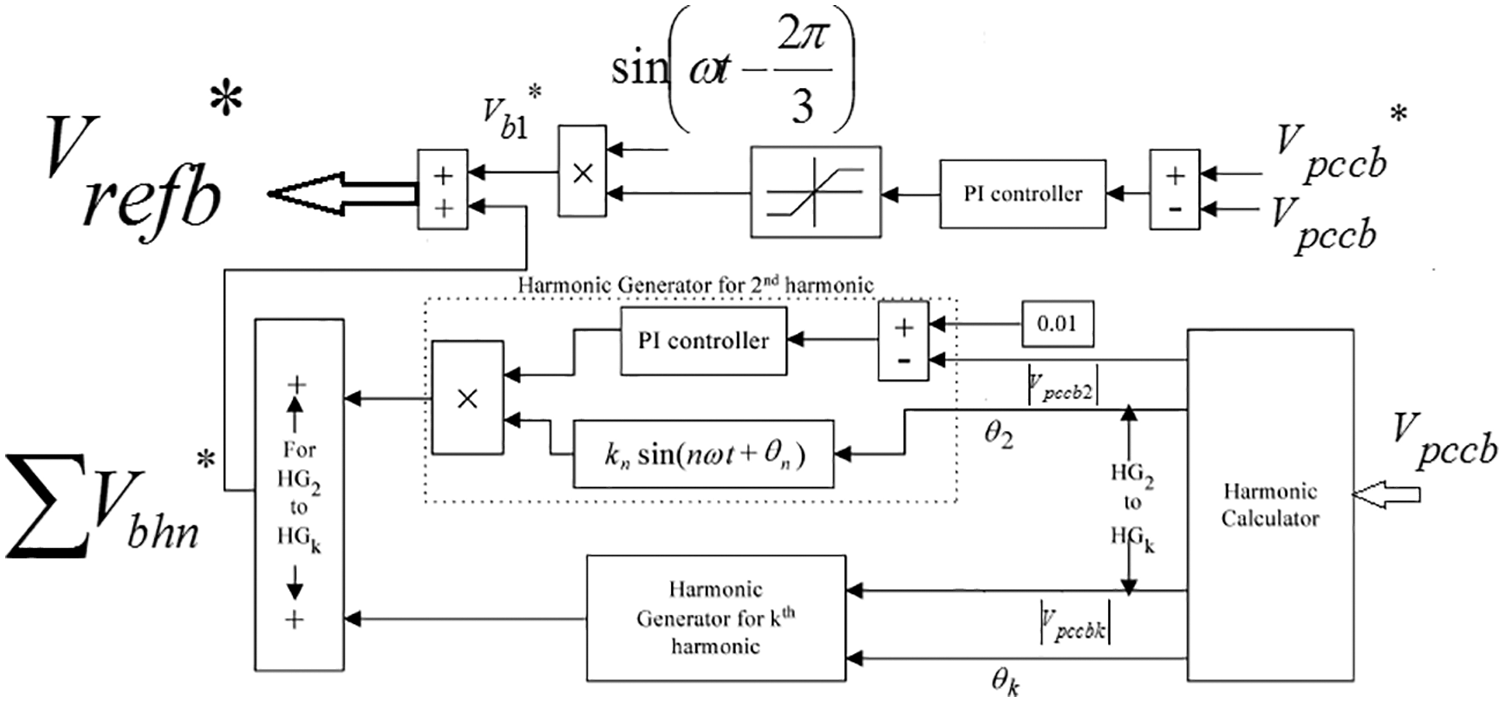
Figure 7: Obtaining the non-sinusoidal reference waveform of phase b
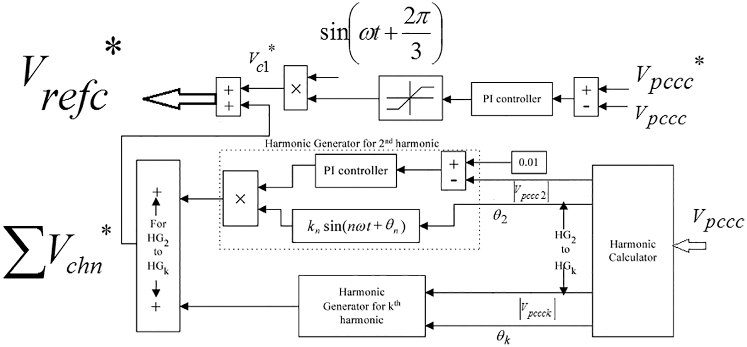
Figure 8: Obtaining the non-sinusoidal reference waveform of phase c
As can be seen in Figs. 6–8, generating non-sinusoidal reference waveforms in each phase has two main loops. The voltage control loop adjusts the PCC voltages,
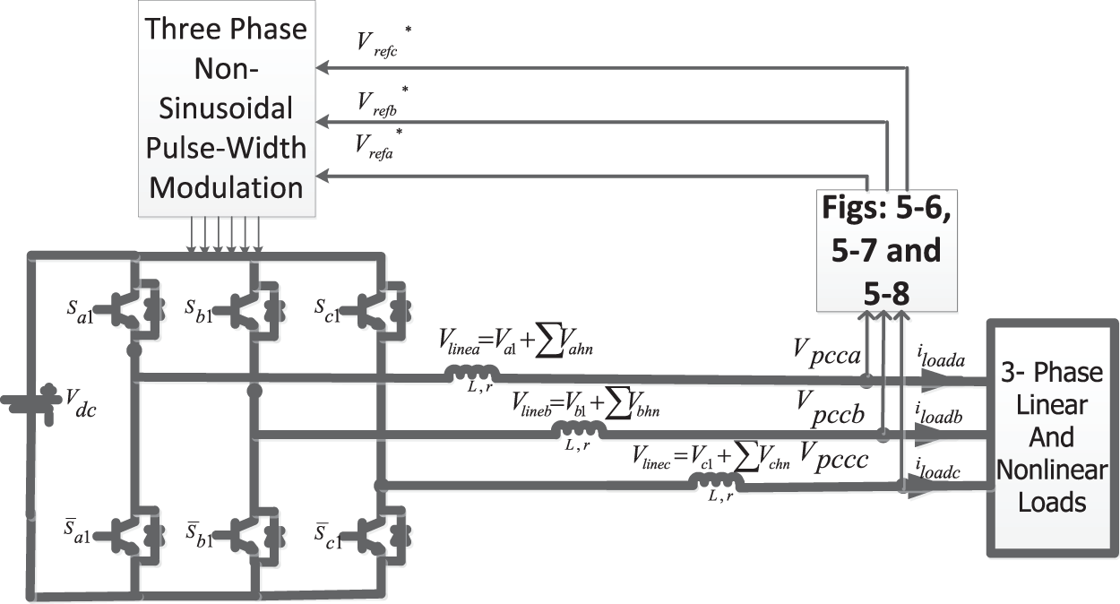
Figure 9: Applying the proposed method to the three-phase DG system in stand-along mode
3.1 Stand-Alone DG System with Linear Loads
To better understand the proposed method, first, the nonlinear loads of Fig. 9 are considered. This linear load includes a 0.5

Figure 10: Three-phase currents of the load
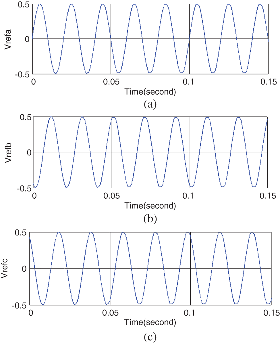
Figure 11: The reference three-phase waveforms generated in the proposed control method
As expected, the voltages of the three-phase PCC are sinusoidal as shown in Fig. 12. The important point is that the three PCC voltages are balanced and satisfy Eq. (11), indicating the correct performance of the controllers shown in Figs. 6–8 that generate the reference voltages. The amplitude of the three-phase voltages of the PCC is 220 V. Figs. 13 and 14 show the active and reactive power consumption of the linear load. The active power consumption of the load is about 7000 W and the average reactive power of the load is zero. All active power of the load is generated by the inverter, and the currents and voltages of all phases are in-phase due to lack of reactive power.
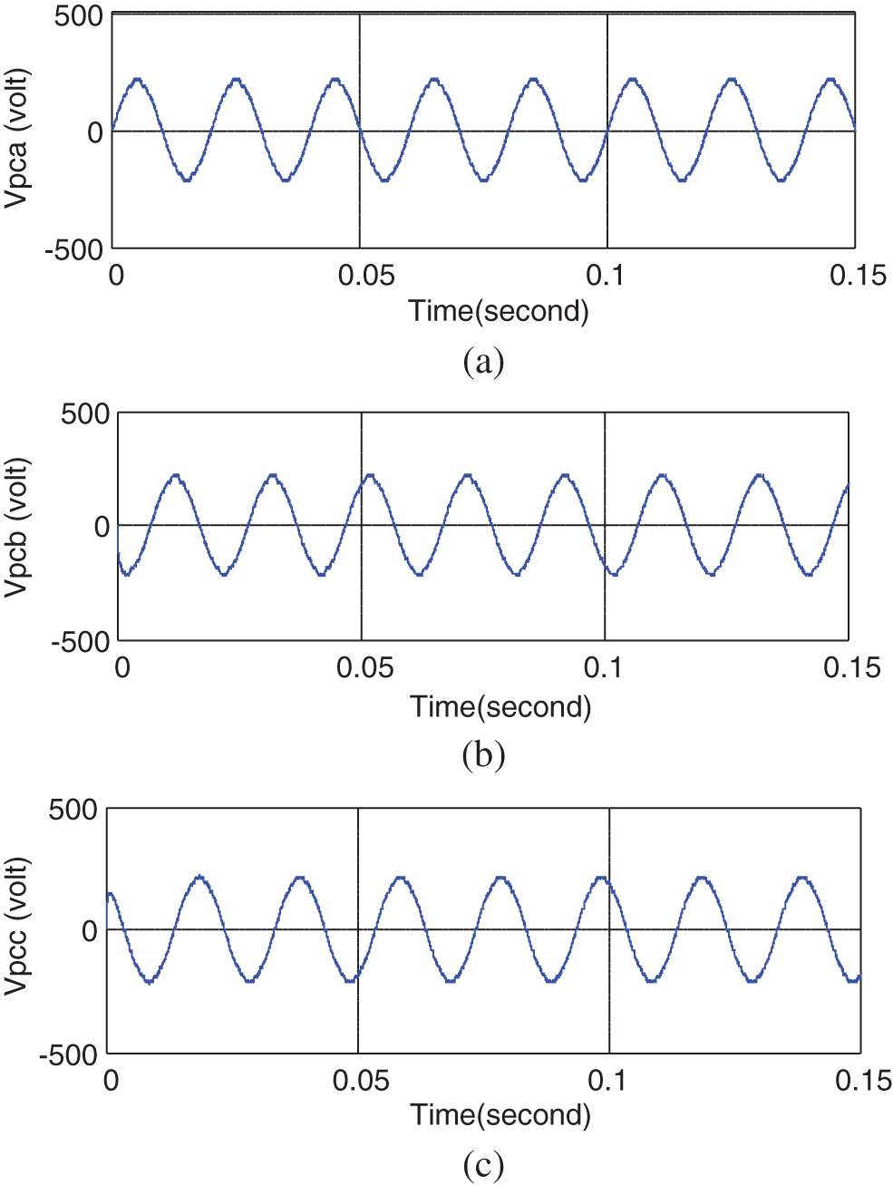
Figure 12: PCC voltages
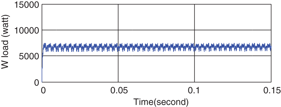
Figure 13: Active power consumption of the load
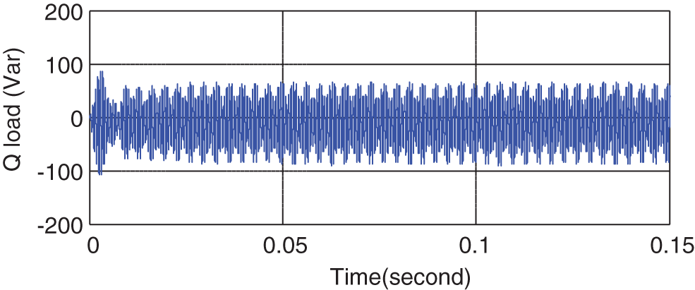
Figure 14: Reactive power consumption of the load
3.2 Stand-Alone DG with Linear and Nonlinear Loads
Now the nonlinear load shown in Fig. 9 is added to the system. This nonlinear load is a full-wave diode rectifier with 20 ohms resistive load. In addition, the system includes a linear load, a 0.5
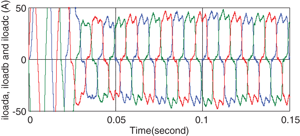
Figure 15: Three-phase currents of the load in the presence of nonlinear load
By calculating the harmonics generated at each phase according to Figs. 6–8, the non-sinusoidal reference waveforms of the NSPWM method are obtained as shown in Fig. 16.
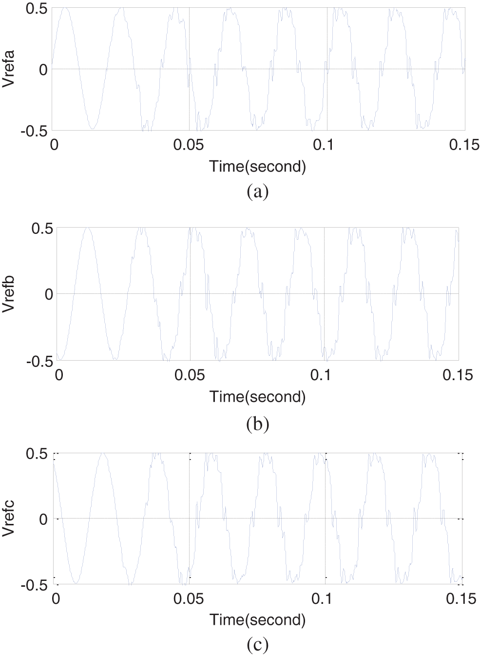
Figure 16: The three-phase reference waveforms generated in the proposed control method in the presence of nonlinear load
As can be seen in Fig. 16, three phases of phases a, b, and c are non-sinusoidal that can generate the harmonics generated at the output of the inverter compared to the high-frequency triangular wave, making the three-phase voltages of the PCC sinusoidal as shown in Fig. 18.
As can be seen in Fig. 17, after a transient state, the voltages of the PCC become balances three-phase sinusoidal with low THD, where the THD values of phases a, b, and c are 4.3, 4.4, and 4.35 that are compatible with the IEEE standard. The purpose is to achieve a balanced PCC voltage with acceptable THD without using compensating elements and sampling the current, which is accomplished. Figs. 18 and 19 shows the active and reactive power consumption of the load.
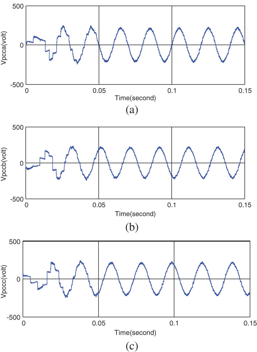
Figure 17: PCC voltages
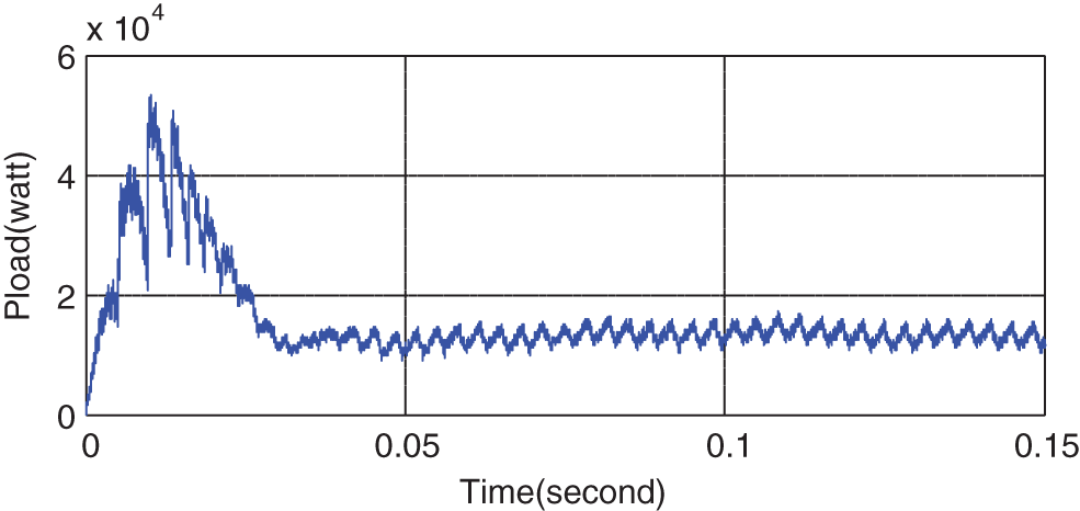
Figure 18: Active power of the linear and nonlinear loads
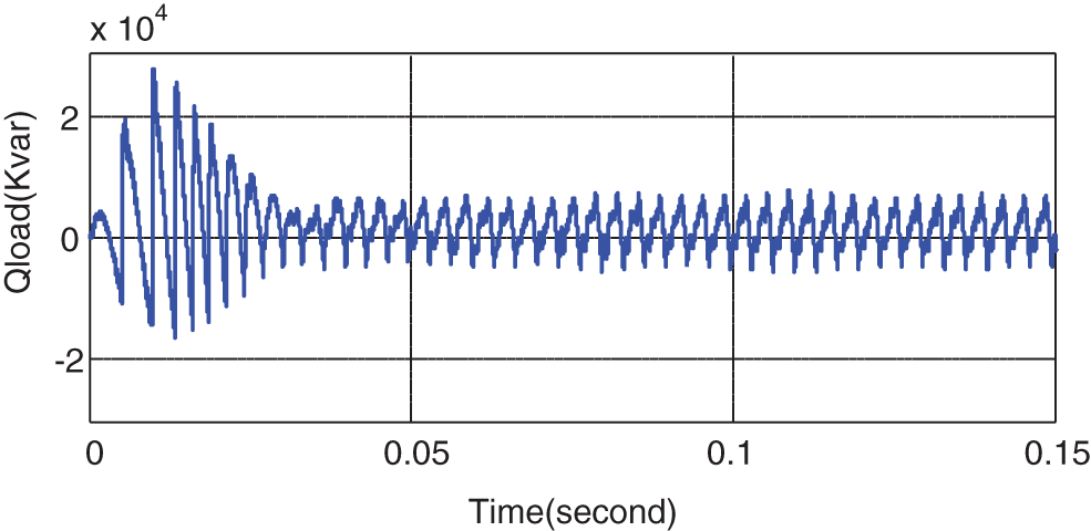
Figure 19: Reactive power of the linear and nonlinear loads
In this paper, a control method is applied to the three-phase stand-alone DG system that does no need any current sensor or compensating element. The control methods applied here including the methods employing the inverter equation, or those taking feedback from the load and inverter currents and using current sensor, increase the cost and complexity of the control method by using series compensators like transformers, passive filters and active filters to improve the PCC voltage quality and achieve an acceptable harmonic level. The results of applying the proposed control method in MATLAB/SIMULINK show that this method can generate balanced three-phase sinusoidal voltage with acceptable THD at the PCC. The THD of phases a, b, and c is 4.3, 4.4, and 4.35 that is compatible with the IEEE standard. In addition, by accurate adjustment of the proportional and integral coefficients of the PI controllers used in the proposed control system, more desired results are obtained. Furthermore, acceptable values are obtained for the amplitude of various harmonic components of the PCC voltage. For future work related to this study, multi-objective methods can be used to solve the problem. This paper also introduced uncertainty issues, such as energy source uncertainty, load uncertainty and measuring-instrument uncertainty into the objective function of the problem.
Funding Statement: This work was supported in part by an International Research Partnership “Electrical Engineering–Thai French Research Center (EE-TFRC)” under the project framework of the Lorraine Université d’Excellence (LUE) in cooperation between Université de Lorraine and King Mongkut’s University of Technology North Bangkok and in part by the National Research Council of Thailand (NRCT) under Senior Research Scholar Program under Grant No. N42A640328, and in part by National Science, Research and Innovation Fund (NSRF) under King Mongkut’s University of Technology North Bangkok under Grant No. KMUTNB-FF-65-20.
Conflicts of Interest: The authors declare that they have no conflicts of interest to report regarding the present study.
References
1. K. S. Tam and S. Rahman, “System performance improvement provided by a power conditioning subsystem for central station photovoltaic- fuel cell power plant,” IEEE Transactions on Energy Conversion, vol. 3, no. 1, pp. 64–70, 1988. [Google Scholar]
2. M. I. Marei, E. F. El-Saadany and M. M. A. Salama, “Flexible distributed generation: (FDG),” IEEE Power Engineering Society Summer Meeting, vol. 1, pp. 49–53, 2002. [Google Scholar]
3. K. Ro and S. Rahman, “Control of grid-connected fuel cell plants for enhancement of power system stability,” Renewable Energy, vol. 28, no. 3, pp. 397–407, 2003. [Google Scholar]
4. K. Ro and S. Rahman, “Two-loop controller for maximizing performance of a grid-connected photovoltaic-fuel cell hybrid power plant,” IEEE Transactions on Energy Conversion, vol. 13, no. 3, pp. 276–281, 1998. [Google Scholar]
5. N. Reddy and V. Agarwal, “Utility interactive hybrid distribution generation scheme with compensation features,” IEEE Transactions on Energy Conversion, vol. 22, no. 3, pp. 666–673, 2007. [Google Scholar]
6. F. Katiraei, M. R. Iravani and P. W. Lehn, “Micro-grid autonomous operation during and subsequent to islanding process,” IEEE Transactions on Power Delivery, vol. 20, no. 1, pp. 248–257, 2005. [Google Scholar]
7. T. Kawabata and S. Highashino, “Parallel operation of voltage source inverters,” IEEE Transactions on Industry Applications, vol. 24, no. 2, pp. 281–287, 1988. [Google Scholar]
8. T. Ackermann and V. Knayzkin, “Interaction between distributed generation and the distribution network: Operation aspects,” IEEE/PES Transmission and Distribution Conference and Exhibition, vol. 2, pp. 1357–1362, 2002. [Google Scholar]
9. V. E. Wagner, J. C. Balda, D. C. Griffith, A. Mc-Eachern, T. M. Barnes et al., “Effect of harmonics on equipment,” IEEE Transactions on Power Delivery, vol. 8, no. 2, pp. 672–680, 1993. [Google Scholar]
10. F. Z. Peng, “Applications issues of active power filters,” IEEE Transactions on Industry Applications, vol. 4, no. 5, pp. 21–30, 1998. [Google Scholar]
11. J. Perez, V. Cardenas, F. Pazos and S. Ramirez, “Voltage harmonic cancellation in single phase systems using a series active filter with a low-order controller,” in VIII IEEE International Power Electronics Congress, IEEE, Guadalajara, Mexico, pp. 270–274, 2002. [Google Scholar]
12. F. Z. Peng, H. Akagi and A. Nabae, “New approach to harmonic compensation in power systems-a combined system of shunt passive and series active filters,” IEEE Transactions on Industry Applications, vol. 26, no. 6, pp. 983–990, 1990. [Google Scholar]
13. Z. Wang, O. Wang, W. Yao and J. Liu, “A series active power filter adopting hybrid control approach,” IEEE Transactions on Power Electronics, vol. 16, no. 3, pp. 301–310, 2001. [Google Scholar]
14. S. George and V. Agarwal, “A DSP based control algorithm for series active filter for optimized compensation under non-sinusoidal and unbalanced voltage conditions,” IEEE Transactions on Power Delivery, vol. 22, no. 1, pp. 302–310, 2007. [Google Scholar]
15. G. A. Tsengenes and G. A. Adamidis, “Study of a simple control strategy for grid connected VSI using SVPWM and p-q theory,” in the XIX Int. Conf. on Electrical Machines-ICEM, Rome, Italy, pp. 1–6, 2010. [Google Scholar]
16. S. Jena, B. Ch. Babu, S. R. Samantaray and M. Mohapatra, “Comparative study between adaptive hysteresis and SVPWM current control for grid-connected inverter system,” in IEEE Technology Students’ Symposium, Kharagpur, India, pp. 310–315, 2011. [Google Scholar]
17. Q. Zeng and L. Chang, “Study of advanced current control strategies for three-phase grid-connected PWM inverters for distributed generation,” in Proc. of the 2005 IEEE Conf. on Control Applications, Toronto, ON, Canada, pp. 1311–1316, 2005. [Google Scholar]
18. H. Patel and V. Agarwal, “Control of a stand-alone inverter-based distributed generation source for voltage regulation and harmonic compensation,” IEEE Transactions on Power Delivery, vol. 23, no. 2, pp. 1113–1120, 2008. [Google Scholar]
19. Y. Wang, C. Li, Y. Zhang, M. Yang, B. Li et al., “Processing characteristics of vegetable oil-based nanofluid MQL for grinding different workpiece materials,” International Journal of Precision Engineering and Manufacturing-Green Technology, vol. 5, no. 2, pp. 327–339, 2018. [Google Scholar]
20. J. Zhang, C. Li, Y. Zhang, M. Yang, D. Jia et al., “Experimental assessment of an environmentally friendly grinding process using nanofluid minimum quantity lubrication with cryogenic air,” Journal of Cleaner Production, vol. 193, pp. 236–248. 2018. [Google Scholar]
21. B. Li, C. Li, Y. Zhang, Y. Wang, D. Jia et al., “Grinding temperature and energy ratio coefficient in MQL grinding of high-temperature nickel-base alloy by using different vegetable oils as base oil,” Chinese Journal of Aeronautics, vol. 29, no. 4, pp. 1084–1095, 2016. [Google Scholar]
22. X. Cui, C. Li, Y. Zhang, Z. Said, S. Debnath et al., “Grindability of titanium alloy using cryogenic nanolubricant minimum quantity lubrication,” Journal of Manufacturing Processes, vol. 80, pp. 273–286, 2022. [Google Scholar]
23. A. E. Anqi, C. Li, H. A. Dhahad, K. Sharma, E. Attia et al., “Effect of combined air cooling and nano enhanced phase change materials on thermal management of lithium-ion batteries,” Journal of Energy Storage, vol. 52, pp. 104906, 2022. [Google Scholar]
24. Y. Yang, M. Yang, C. Li, R. Li, Z. Said et al., “Machinability of ultrasonic vibration assisted micro-grinding in biological bone using nanolubricant,” Frontiers of Mechanical Engineering, vol. 17, no. 2, pp. 283–296, 2022. [Google Scholar]
25. Z. Li, X. Peng, G. Hu, D. Zhang, Z. Xu et al., “Towards real-time self-powered sensing with ample redundant charges by a piezostack-based frequency-converted generator from human motions,” Energy Conversion and Management, vol. 258, no. 1, pp. 115466, 2022. [Google Scholar]
26. Y. Peng, Z. Xu, M. Wang, Z. Li, J. Peng et al., “Investigation of frequency-up conversion effect on the performance improvement of stack-based piezoelectric generators,” Renewable Energy, vol. 172, pp. 551–563, 2021. [Google Scholar]
27. D. Yu, Z. Ma and R. Wang, “Efficient smart grid load balancing via fog and cloud computing,” Mathematical Problems in Engineering, vol. 2022, pp. 1–11, 2022. [Google Scholar]
28. D. Yu, J. Wu, W. Wang and B. Gu, “Optimal performance of hybrid energy system in the presence of electrical and heat storage systems under uncertainties using stochastic p-robust optimization technique,” Sustainable Cities and Society, vol. 83, pp. 103935, 2022. [Google Scholar]
29. L. Zhang, H. Zhang and G. Cai, “The multi-class fault diagnosis of wind turbine bearing based on multi-source signal fusion and deep learning generative model,” IEEE Transactions on Instrumentation and Measurement, vol. 71, pp. 1–12, 2022. [Google Scholar]
30. D. Li, S. S. Ge and T. H. Lee, “Fixed-time-synchronized consensus control of multiagent systems,” IEEE Transactions on Control of Network Systems, vol. 8, no. 1, pp. 89–98, 2022. [Google Scholar]
31. L. Zhang, H. Zheng, G. Cai, Z. Zhang, X. Wang et al., “Power-frequency oscillation suppression algorithm for AC microgrid with multiple virtual synchronous generators based on fuzzy inference system,” IET Renewable Power Generation, vol. 16, no. 8, pp. 1589–1601, 2022. [Google Scholar]
32. G. Li, H. Yuan, J. Mou, E. Dai, H. Zhang et al., “Electrochemical detection of nitrate with carbon nanofibers and copper co-modified carbon fiber electrodes,” Composites Communications, vol. 29, pp. 101043, 2022. [Google Scholar]
33. C. Zhong, H. Li, Y. Zhou, Y. Lv, J. Chen et al., “Virtual synchronous generator of PV generation without energy storage for frequency support in autonomous microgrid,” International Journal of Electrical Power and Energy Systems, vol. 134, pp. 107343, 2022. [Google Scholar]
34. C. Zong, H. Wang and W. Zhibo, “An improved 3D point cloud instance segmentation method for overhead catenary height detection,” Computers and Electrical Engineering, vol. 98, pp. 107685, 2022. [Google Scholar]
35. W. Zhou, H. Wang and Z. Wan, “Ore image classification based on improved CNN,” Computers and Electrical Engineering, vol. 99, pp. 107819, 2022. [Google Scholar]
36. Y. Peng, L. Zhang, Z. Li, S. Zhong, Y. Liu et al., “Influences of wire diameters on output power in electromagnetic energy harvester,” International Journal of Precision Engineering and Manufacturing-Green Technology, vol. 56, pp. 1–12, 2022. [Google Scholar]
37. H. Zhou, C. Xu, C. Lu, X. Jiang, Z. Zhang et al., “Investigation of transient magnetoelectric response of magnetostrictive/piezoelectric composite applicable for lightning current sensing,” Sensors and Actuators: A Physical, vol. 329, pp. 112789, 2021. [Google Scholar]
38. C. Lu, R. Zhu, F. Yu, X. Jiang, Z. Liu et al., “Gear rotational speed sensor based on FeCoSiB/Pb(Zr,Ti)O3 magnetoelectric composite,” Measurement, vol. 168, pp. 108409, 2021. [Google Scholar]
39. S. Liu, C. Liu, Z. Song, Z. Dong and Y. Huang, “Candidate modulation patterns solution for five-phase PMSM drive system,” IEEE Transactions on Transportation Electrification, vol. 8, no. 1, pp. 1194–1208, 2021. [Google Scholar]
40. C. Lu, H. Zhou, L. Li, A. Yang, C. Xu et al., “Split-core magnetoelectric current sensor and wireless current measurement application,” Measurement, vol. 188, pp. 110527, 2022. [Google Scholar]
41. H. Wang, X. Wu, X. Zheng and X. Yuan, “Virtual voltage vector based model predictive control for a nine-phase open-end winding PMSM with a common DC bus,” IEEE Transactions on Industrial Electronics, vol. 69, no. 6, pp. 5386–5397, 2022. [Google Scholar]
42. J. Yang, H. Liu, K. Ma, B. Yang and J. M. Guerrero, “An optimization strategy of price and conversion factor considering the coupling of electricity and gas based on three-stage game,” IEEE Transactions on Automation Science and Engineering, vol. x, pp. 1–14, 2022. [Google Scholar]
43. K. Ma, X. Hu, Z. Yue, Y. Wang, J. Yang et al., “Voltage regulation with electric taxi based on dynamic game strategy,” IEEE Transactions on Vehicular Technology, vol. 71, no. 3, pp. 2413–2426, 2022. [Google Scholar]
44. L. Guo, C. Ye, Y. Ding and P. Wang, “Allocation of centrally switched fault current limiters enabled by 5G in transmission system,” IEEE Transactions on Power Delivery, vol. 36, no. 5, pp. 3231–3241, 2020. [Google Scholar]
45. C. Guo, C. Ye, Y. Ding and P. Wang, “A Multi-state model for transmission system resilience enhancement against short-circuit faults caused by extreme weather events,” IEEE Transactions on Power Delivery, vol. 36, no. 4, pp. 2374–2385, 2020. [Google Scholar]
46. K. Wang, B. Zhang, F. Alenezi and S. Li, “Communication-efficient surrogate quantile regression for non-randomly distributed system,” Information Sciences, vol. 588, pp. 425–441, 2022. [Google Scholar]
47. L. Liu, X. Meng, Z. Miao and S. Zhou, “Design of a novel thermoelectric module based on application stability and power generation,” Case Studies in Thermal Engineering, vol. 31, pp. 101836, 2022. [Google Scholar]
Cite This Article
 Copyright © 2023 The Author(s). Published by Tech Science Press.
This work is licensed under a Creative Commons Attribution 4.0 International License , which permits unrestricted use, distribution, and reproduction in any medium, provided the original work is properly cited.
 Downloads
 Citation Tools