
 Submit a Paper
 Propose a Special lssue
 Open Access
ARTICLE
LoRa Backscatter Network Efficient Data Transmission Using RF Source Range Control
1 Department of Computer Software Engineering, Soonchunhyang University, Asan, 31538, Korea
2 Department of Software Convergence, Soonchunhyang University, Asan, 31538, Korea
* Corresponding Author: Seokhoon Kim. Email:
Computers, Materials & Continua 2023, 74(2), 4015-4025. https://doi.org/10.32604/cmc.2023.027078
Received 11 January 2022; Accepted 05 May 2022; Issue published 31 October 2022
 View Full Text
 Download PDF
Abstract
Networks based on backscatter communication provide wireless data transmission in the absence of a power source. A backscatter device receives a radio frequency (RF) source and creates a backscattered signal that delivers data; this enables new services in battery-less domains with massive Internet-of-Things (IoT) devices. Connectivity is highly energy-efficient in the context of massive IoT applications. Outdoors, long-range (LoRa) backscattering facilitates large IoT services. A backscatter network guarantees timeslot-and contention-based transmission. Timeslot-based transmission ensures data transmission, but is not scalable to different numbers of transmission devices. If contention-based transmission is used, collisions are unavoidable. To reduce collisions and increase transmission efficiency, the number of devices transmitting data must be controlled. To control device activation, the RF source range can be modulated by adjusting the RF source power during LoRa backscatter. This reduces the number of transmitting devices, and thus collisions and retransmission, thereby improving transmission efficiency. We performed extensive simulations to evaluate the performance of our method.Keywords
Recent advances in computer systems have made it possible to collect and transport information using small devices with hyper-connectivity and wireless communication capabilities; these Internet-of-Things (IoT) devices provide services through the collected information. The IoT involves long-range (LoRa) communications including Long Term Evolution Category M1 (LTE-M), NarroBand-Internet of Things (NB-IoT), and long-range wide-area networks (LoRaWANs). The IoT enables intelligent management of smart cities, in which many sensors and actuators are connected to a wide-area network (WAN) network. Information needed for city management is collected from IoT devices and used to provide intelligent services. For smart-city application, energy-constrained IoT devices are essential, but pose challenges for IoT engineers [1–5].
To reduce energy consumption, many IoT devices use low-power systems including ZigBee, Bluetooth Low Energy (BLE), and LoRa systems. However, all battery-driven devices consume power. IoT devices for smart cities may be located in inaccessible places, and battery replacement may be very difficult or impossible; battery-less communication is thus required. One solution to this is backscatter communication (BackCom); power is delivered by an external radio frequency (RF) source [2,3,6,7] and the devices transmit data. The signal received at the power source is remodulated and reflected, and the information is then transmitted. A typical BackCom network has an RF source, and a backscatter sender and receiver [8,9]. Fig. 1 shows a typical network. The RF source generates an incident signal from which the BackCom device harvests energy used to transmit data to a receiver.
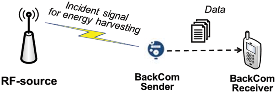
Figure 1: A typical BackCom network
BackCom systems are classified as monostatic or bistatic [8]. In a monostatic system, the RF source includes the BackCom receiver. The BackCom device receives the incident signal, harvests energy, and transmits data to the RF source. In contrast, a bistatic BackCom system separates the BackCom receiver from the RF source. The device receives a signal from the RF source and transmits data to the BackCom receiver. Both systems can be applied to smart cities. Fig. 2 shows monostatic and bistatic BackCom systems.
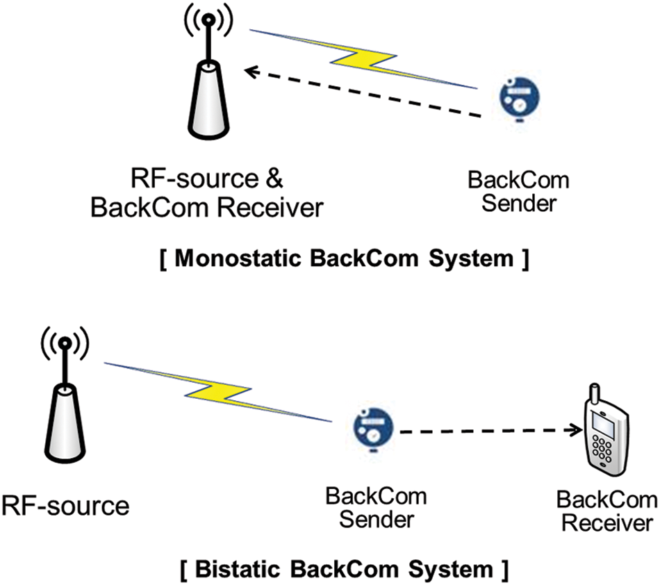
Figure 2: Monostatic and bistatic BackCom systems
LoRa communications are characterized by very low data transmission rates within narrow frequency bands and generally involve simple contention-based medium access control protocols, such as Additive Links On-line Hawaii Area (ALOHA) random access. Thus, if collisions occur, data are retransmitted, which causes long delays. As mentioned above, several LoRa communication devices are available. When all of them transmit data, the probability of collisions increases, requiring frequent retransmission. LoRa backscattering systems exhibit severe energy constraints that affect their behavior. It is important to reduce the collision probability during data transmission. The backscattering devices of BackCom systems are activated using incident signals as energy sources; the devices then deliver data. Thus, by adjusting the range of the incident signal, the number of activated BackCom devices in the network can be changed. When the number of activated devices is reduced, transmission collisions are reduced. We controlled BackCom device activation by adjusting the transmission power of the RF incident signal. The transmission powers of RF modules for LoRa communication can be adjusted to control the range of the incident signal.
The rest of this paper is organized as follows. Section 2 describes relevant work on LoRa BackCom systems. Section 3 presents the method that we use to control activation of BackCom devices. Section 4 presents extensive computer simulations for performance evaluation. Section 5 provides the conclusions.
In massive IoT services, many IoT devices operate in various bservice domains. Not all battery-driven devices can support large IoT services such as smart-city applications. As mentioned above, it may be impossible to replace or recharge the batteries of some IoT devices. Battery-driven and BackCom devices may be deployed together in large-scale IoT services. BackCom devices use wireless power to operate in an “energy harvest-then-transmit” manner [6,10]. Energy harvesting is a major challenge. BackCom devices use two types of RF sources. The first is a dedicated source, termed a power beacon center (PB-center). BackCom devices receive RF signals from PB-centers and harvest energy. When the energy is adequate, BackCom devices attempt to transmit data. If there is no PB-center, BackCom devices need another RF source, and thus employ ambient RF signals such as cellular, TV broadcast, and public WiFi signals [8].
In LoRa communication technologies, the RF source can activate BackCom devices over a large range. When a BackCom device receives a signal from a LoRa gateway, the signal power is determined by the transmission power of the gateway and the path loss of the signal (PL) [11] (Eq. (1)), i.e., the sum of the signal-to-noise ratio (SNR) gain (γ) and noise power (Pn).
where d is the distance (km) between the RF source and BackCom device. For outdoor communication, the path loss is that of the International Telecommunication Union (ITU) [1]. In line-of-sight (LoS) operation, the wireless path loss is given by Eq. (2):
where d is as in Eq. (1) and fc is the carrier frequency (MHz). When the transmission power and distance from the RF source are known, the received power can be calculated; if this exceeds the receiver sensitivity, the BackCom device harvests energy and transmits data.
A general BackCom system allows a single receiver to connect to multiple BackCom devices. For multiple wireless access points, several access technologies are required. A BackCom system may employ conventional media access technologies including space division multiple access (SDMA), frequency division multiple access (FDMA), code division multiple access (CDMA), time division multiple access (TDMA), and carrier sense multiple access (CSMA). SDMA searches the available space for communications; however, a directional antenna is required, which increases complexity. FDMA divides the frequency band, but operation is complex when processing signals in the frequency domain. CDMA allocates orthogonal codes to the devices for signal modulation, but this increases system complexity. As mentioned above, LoRa BackCom devices have inadequate computing resources [8]. As the energy requirements are large, SDMA, FDMA, and CDMA cannot be used, so TDMA and CSMA are applied. TDMA guarantees stable transmission without collisions. However, in LoRa IoT applications, the devices activated to transmit data change frequently. In such a scenario, TDMA cannot provide scalability. CSMA allows any device to transfer data. Although collisions occur, CSMA allows scalability of large-scale networks. Therefore, when CSMA is applied to LoRa BackCom systems, a method that reduces collisions is required.
We controlled the transmission power of the RF source to in turn control the activation of BackCom devices in a network. By adjusting the RF signal range, the number of activated BackCom devices is controlled and the collision probability during channel access is reduced.
LoRa communication-based backscattering covers wide areas. The LoRa gateway serves as both the RF signal source and data collector. We used a monostatic system wherein BackCom devices transmit data to the RF source after harvesting energy for operation (as mentioned above). To transmit data wirelessly, we use simple contention-based media access control (ALOHA). LoRa communication uses a narrow industrial, scientific, and medical (ISM) frequency band (915 MHz in the USA) and data transmission is slow [12,13]. Although retransmission is possible, it should be minimized. To improve the probability of successful data transmission, it is necessary to adjust the number of devices participating in transmission by varying radio channel operation. This reduces the risk of data collisions during transmission. In LoRa BackCom systems, the BackCom devices harvest energy and then attempt data transfer. Several forms of transmission power may be employed; the RF signal range can be adjusted by configuring the power configurations [12]. Activation of BackCom devices is controlled by varying the range of the RF source.
Fig. 3 shows the pseudo-code for RF source range control of LoRa BackCom systems. The system employs two parameters: TxLv and RCnt. TxLv is the transmission power of the LoRa RF source. RCnt is a count (variable) that controls the LoRa transmission power from level 0–10 [11]. The maximum transmission power (level 0) is 30 dBm and the minimum transmission power (level 10) 10 dBm. Transmission power is reduced by 2 dBm for each level (Eq. (3).
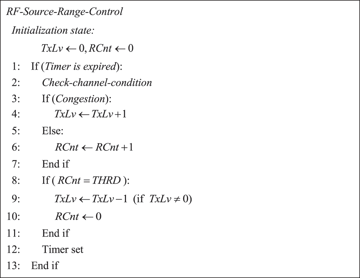
Figure 3: Pseudo-code for the RF-source range control
On initialization, all parameters are set to 0. The system adjusts the RF source range by changing the parameters when a certain amount of time has elapsed (line 1). Before this adjustment, the LoRa gateway checks the channel conditions. Recently, machine-learning algorithms have been applied in various ways to recognize channel conditions such as congestion [14–16]. There are several possible methods, which we do not discuss them here. If the channel is congested, the number of devices participating in data transmission is decreased by reducing the RF source range (i.e., the transmission power). TxLv is increased by 1. If there is no congestion, RCnt is increased by 1 (lines 2–7). When RCnt reaches its threshold, TXLv is lowered by 1, RCnt is initialized to increase the transmission power of the RF source (lines 8–11), and the timer is reset (line 12). If the congestion is severe, the RF source quickly decreases the signal power; otherwise, it increases the power gradually.
3.2 RF Source Transmission Power Analysis
The transmission range according to the transmission power can be analyzed using Eqs. (1)–(3). Eq. (1) determines the power received by a device. In general, when this is higher than the receiver sensitivity, the device recognizes received data. BackCom devices require high levels of received power for energy harvesting. The received power is related to the energy harvesting efficiency. Thus, a low received power requires a long energy harvesting time. Therefore, high-powered RF signals are optimal. During 915-MHz LoRa communication, the receiver sensitivity is–121 dBm for a 10 kbps data rate [17]. To decode data from the received signal, the received power should be higher than the receiver sensitivity. If the energy harvesting level of a BackCom device is assumed to be 35 dB, the receiver sensitivity becomes–86 dBm. The activation ranges of BackCom devices according to the transmission power of the RF source are listed in Tab. 1
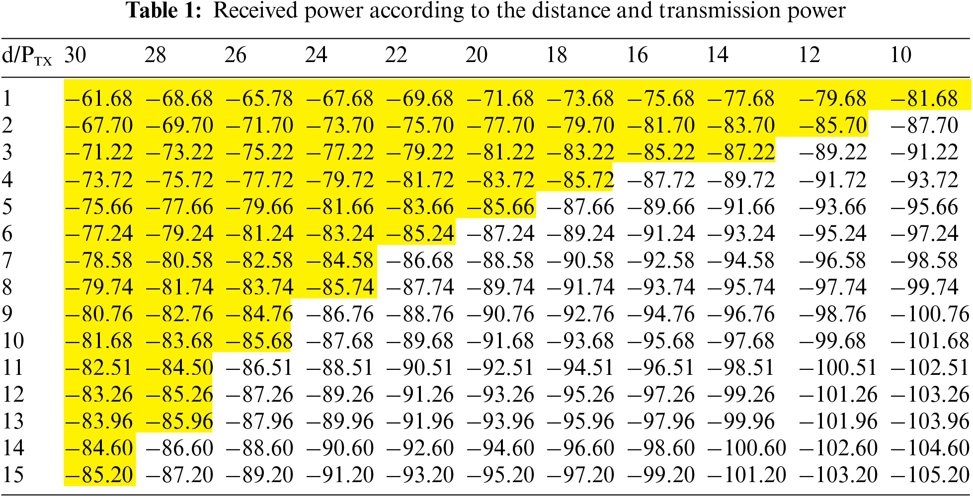
where the yellow area indicates the activation range. When the transmission power is reduced, the activation range is also reduced. The BackCom devices transmit data within the activation range. If the received RF signal is less than the receiver sensitivity of the BackCom device, the device waits for the next opportunity to transmit. Thus, by adjusting the transmission power of the incident signal from the RF source, the number of BackCom devices participating in the network can be adjusted.
3.3 Data Transmission Control for BackCom Devices
After energy harvesting, BackCom devices decide whether to transmit data (depending on their activation status). Devices near the RF source can always transmit data. In contrast, distant devices cannot transmit if the RF signal does not reach them. To avoid such “unfairness”, a data transmission control system is necessary. In our method, the unfairness problem is solved by transmission priority. The devices that lose a transmission opportunity after energy harvesting are prioritized over devices near the RF source. Thus, when a device with a high priority obtains another transmission opportunity, it transmits data rapidly. Fig. 4 shows the data transmission control system.
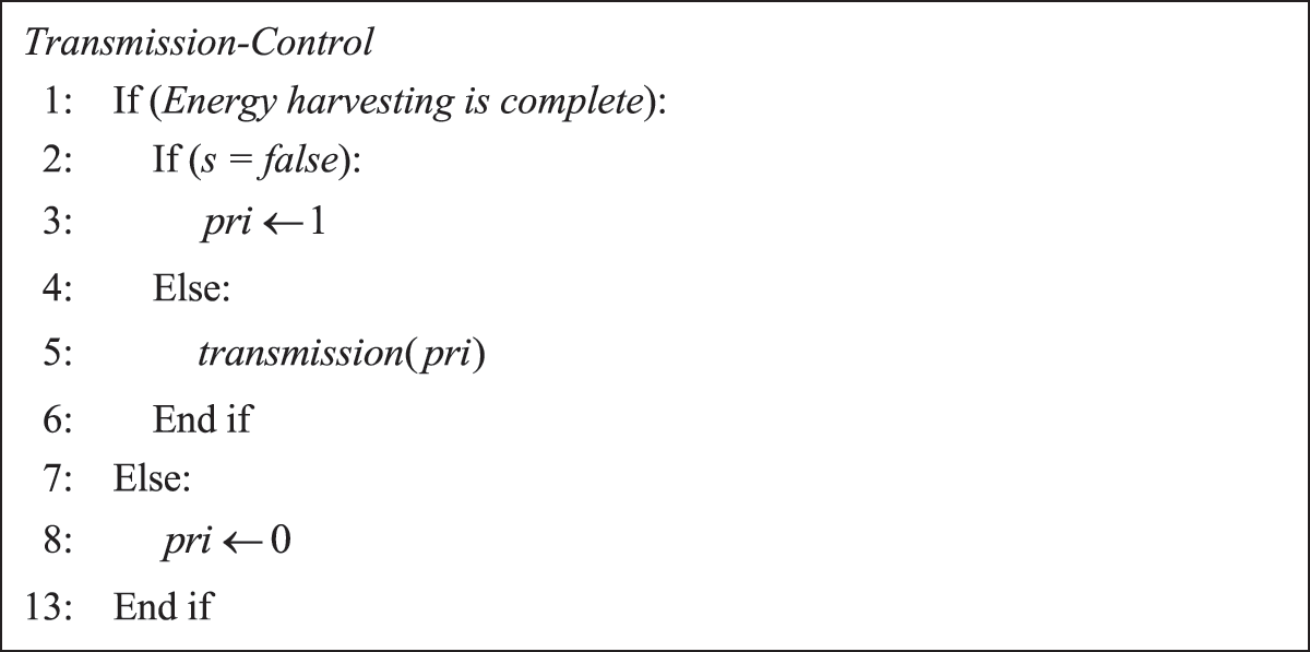
Figure 4: Pseudo-code for data transmission control
As mentioned above, BackCom devices transmit data after energy harvesting. If no energy is harvested, transmission occurs (line 1). When energy harvesting is complete, the device state is classified into one of two types depending on the reception of the RF signal. The device is placed in or out of the RF source range using source range control. If an RF signal does not reach the device, that device (now with a high transmission priority) waits for the next transmission opportunity. Otherwise, the device attempts to transmit using its existing transmission priority (lines 2–6). The method prioritizes devices that miss transmission opportunities; this prevents the unfairness caused by RF source range control.
We tested our method and a typical LoRa backscattering system using C and the SMPL library [18] for event-driven simulation (Section 4.1 below). The three performance metrics tested were goodput, the average transmission delay, and the average power of the RF source.
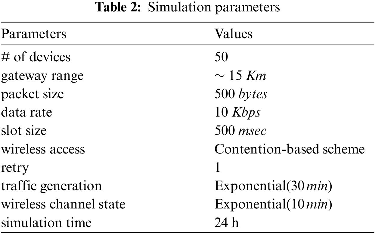
The simulated BackCom network had a single gateway node and 50 BackCom devices deployed randomly within 15 km of the RF source gateway (which periodically broadcasts an RF signal for energy harvesting by the BackCom devices). When an event occurs, data traffic are generated in the devices and transmitted to the gateway via single-hop transmission. The traffic generation exhibits an exponential distribution (mean: 30 min). The data packet size is 500 bytes and the data transfer rate is 10 kbps. The LoRa transmission slot time is 500 ms [12]. A contention-based system is employed for data transmission. The wireless channel state changes exponentially (mean: 10 min); this state determines the collision probability. If transmission fails because of a collision, one retry is allowed. The wireless channel state and collision probability are modeled in Section 4.2. The simulation time is 24 h. Tab. 2 lists the simulation parameters.
The wireless channel is modeled using a two-state Markov chain. The states may be good or bad; the state transition probabilities are p and q from good to bad and bad to good, respectively. When the state transition probabilities are as shown in Fig. 5, the stationary probability in each state is the limiting probability of the Markov chain [19,20].
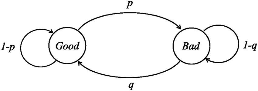
Figure 5: The wireless channel model
The probabilities of good and bad states are calculated as follows:
The transition probabilities p and q are set to 0.6 and 0.3. The wireless state probability is determined by these probabilities, and the state probability affects the collision probability. The collision probability can be calculated from the Poisson distribution [19,21]. The random variable X is the number of data packets in the wireless channel. The probability that there are n packets is:
where λ is the inter-arrival time of data packets and t is the slot time. For successful data transmission, there should be no packets in the channel. Thus, when n is 0, data transmission is successful (i.e., there are no collisions). This probability is given by:
The collision probability becomes:
The collision probability depends on the value of λ, which varies according to the wireless channel state. In the simulation, the values of the conventional method (bad and good states) are 0.7 and 0.2, respectively. However, in our method, λ can be adjusted via RF signal range control. Initially, λ is set to the value of the conventional method depending on the channel state. Thereafter, for a bad state, the transmission power level of the RF source is used to determine λ, as follows:
Fig. 6 shows the goodput (ratio of successful transfers to total transfer attempts). Our method performs better than the conventional method. When a wireless channel is in high demand, transmission failures are frequent (because of collisions). Our method adjusts the RF signal range to reduce the collision probability by restricting the number of activated BackCom devices. Transmission efficiency and goodput thus improve.
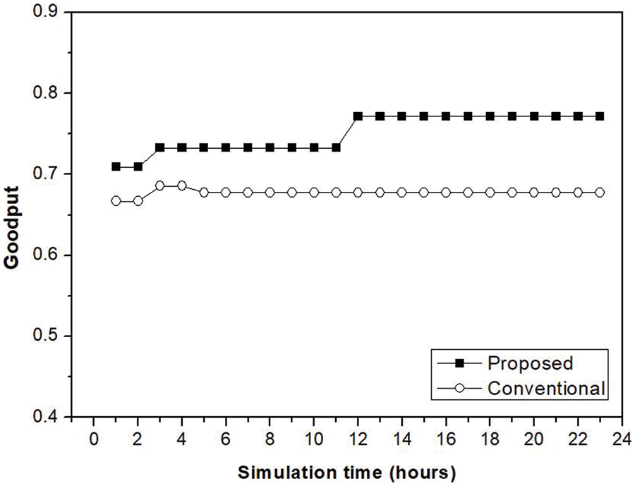
Figure 6: Simulation result: goodput
Fig. 7 shows the average transmission delays during BackCom uplink transmission. These delays are reduced because transmission efficiency is improved via RF signal range control. The transmission delays of devices deprived of transmission opportunities increase after energy harvesting. However, these devices have higher priority during the next transmission opportunity. The results show that the average transmission delay of our method is lower than that of the conventional method because there are fewer collisions caused by congestion. It is important to control the number of active devices to enhance transmission efficiency.
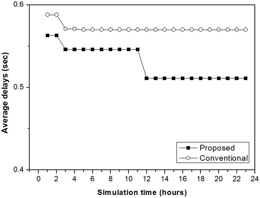
Figure 7: Simulation result: average transmission delays
Fig. 8 shows the average RF signal power at the gateway, which is controlled. If the power is reduced, the signal is reduced, as is the number of activated BackCom devices and, by extension, the collision probability. Gateway power consumption is also reduced. The conventional method uses the maximum possible RF signal power. However, our method controls the RF signal power. As the simulation progresses, gateway power consumption falls.
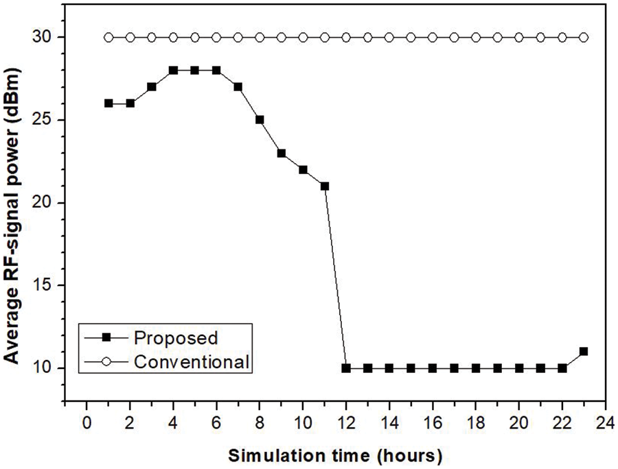
Figure 8: Simulation result: average RF-signal power at the gateway
BackCom allows devices to transmit data after harvesting energy; no power source is required. A LoRa backscatter network provides valuable services within the battery-less domains of massive IoTs. In a backscatter system, a gateway broadcasts an RF signal for energy harvesting. Using this signal, backscatter devices within the RF signal range are activated and transmit data. In a LoRa backscatter system, multiple devices transmit data when an event occurs, leading to data collisions that reduce transmission efficiency. It is essential to reduce the collision probability; this is made possible by reducing the number of activated devices. In our method, we use the RF signal power to this end, and performance was better than the conventional method in terms of goodput and average transmission delay; gateway power consumption was also reduced.
Funding Statement: This work was supported by the National Research Foundation of Korea(NRF) grant funded by the Korea Government(MSIT) (No. 2021R1C1C1013133), and this research was supported by Basic Science Research Program through the National Research Foundation of Korea(NRF) funded by the Ministry of Education(NRF-2020R1I1A3066543), and this work was supported by the Soonchunhyang University Research Fund.
Conflicts of Interest: The authors declare that they have no conflicts of interest to report regarding the present study.
References
1. M. U. Sheihk, B. Xie, K. Ruttik, H. Yiğitler, R. Jäntti et al., “Ultra-low-power wide range backscatter communication using cellular generated carrier,” Sensors, vol. 21, no. 8, pp. 1–25, Article ID 2663, 2021. [Google Scholar]
2. W. Liu, K. Huang, X. Zhou and S. Durrani, “Next generation backscatter communication: Systems, techniques, and applications,” EURASIP Journal on Wireless Communications and Networking, vol. 2019, pp. 1–11, Article ID 69, 2019. [Google Scholar]
3. Q. Liu, S. Sun, H. Wang and S. Zhang, “6G green IoT networks: Joint design of intelligent reflective surface and ambient backscatter communication,” Wireless Communications and Mobile Computing, vol. 2021, pp. 1–10, Article ID 9912265, 2021. [Google Scholar]
4. W. Yang, X. Jing, H. Huang, C. Zhu, Q. Jiang et al., “An efficient markov chain based channel model for 6G enabled massive internet of things,” KSII Transactions on Internet and Information Systems, vol. 15, no. 11, pp. 4203–4223, 2021. [Google Scholar]
5. S. Alnefaie, A. Cherif and S. Alshehri, “A distributed fog-based access control architecture for IoT,” KSII Transactions on Internet and Information Systems, vol. 15, no. 12, pp. 4545–4566, 2021. [Google Scholar]
6. K. Han and K. Huang, “Wirelessly powered backscatter communication networks: Modeling, coverage and capacity,” IEEE Transactions on Wireless Communications, vol. 16, no. 4, pp. 2548–2561, 2017. [Google Scholar]
7. Y. Ge, Y. Nan and Y. Chen, “Maximizing information transmission for energy harvesting sensor networks by an uneven clustering protocol and energy management,” KSII Transactions on Internet and Information Systems, vol. 14, no. 4, pp. 1419–1436, 2020. [Google Scholar]
8. J. -P. Niu and G. Y. Li, “An overview on backscatter communications,” Journal of Communications and Information Networks, vol. 4, no. 2, pp. 1–14, 2019. [Google Scholar]
9. V. Talla, M. Hessar, B. Kellogg, A. Najafi, J. R. Smith et al., “LoRa backscatter: Enabling the vision of ubiquitous connectivity,” in Proceedings of the ACM on Interactive, Mobile, Wearable and Ubiquitous Technologies, vol. 1, no. 3, pp. 1–24, Article ID 105, 2017. [Google Scholar]
10. B. Lyu, Z. Yang, G. Gui, Y. Feng, “Wireless powered communication networks assisted by backscatter communication,” IEEE Access, vol. 5, pp. 7254–7262, 2017. [Google Scholar]
11. D. -Y. Kim, Z. Jin, J. Choi, B. Lee and J. Cho, “Transmission power control with the guaranteed communication reliability in WSN,” International Journal of Distributed Sensor Networks, vol. 2015, pp. 1–13, Article ID 632590, 2015. [Google Scholar]
12. L. Alliance, “LoRa alliance long range wide area network (LoRaWAN) specification,” LoRaWAN Specification, vol. 1.1, pp. 1–101, 2017. [Google Scholar]
13. D. -Y. Kim, S. Kim and J. H. Park, “A combined network control approach for the edge cloud and LPWAN-based IoT services,” Concurrency and Computation: Practice and Experience, vol. 32, no. 1, pp. 1–10, Article ID e4406, 2020. [Google Scholar]
14. C. Zhang, P. Patras and H. Haddadi, “Deep learning in mobile and wireless networking: A survey,” IEEE Communications Surveys & Tutorials, vol. 21, pp. 2224–2287, 2019. [Google Scholar]
15. D. -Y. Kim and S. Kim, “Network-aided intelligent traffic steering in 5G mobile networks,” Computers, Materials & Continua, vol. 65, no. 1, pp. 243–261, 2020. [Google Scholar]
16. S. Kim, D. -Y. Kim and J. H. Park, “Traffic management in the mobile edge cloud to improve the quality of experience of mobile video,” Computer Communications, vol. 118, pp. 40–49, 2018. [Google Scholar]
17. SEMTECH, “LoRaTM modulation basics,” Application Note AN1200.22, rev. 2, pp. 1–26, 2015. [Google Scholar]
18. M. H. MacDougall, in Simulating Computer Systems, Techniques and Tool, MIT Press: Cambridge, MA, USA, 1987. [Google Scholar]
19. S. M. Ross, in Probability Models for Computer Science, Harcourt/Academic Press, Orlando, USA, 2001. [Google Scholar]
20. K. S. Trivedi, in Probability and Statistics with Reliability, Queuing and Computer Science Applications, JohnWiley & Sons: Chichester, UK, 2002. [Google Scholar]
21. D. -Y. Kim and S. Kim, “Dual-channel medium access control of low power wide area networks considering traffic characteristics in IoE,” Cluster Computing, vol. 20, no. 3, pp. 2375–2384, 2017. [Google Scholar]
Cite This Article
 Copyright © 2023 The Author(s). Published by Tech Science Press.
This work is licensed under a Creative Commons Attribution 4.0 International License , which permits unrestricted use, distribution, and reproduction in any medium, provided the original work is properly cited.
 Downloads
 Citation Tools