
 Submit a Paper
 Propose a Special lssue
 Open Access
ARTICLE
Analysis of LDPC Code in Hybrid Communication Systems
1 Department of Electrical Engineering, The University of Lahore, Lahore, 54000, Pakistan
2 Department of Data Science, University of Punjab, Lahore, 54000, Pakistan
* Corresponding Author: Hasnain Kashif. Email:
Computers, Materials & Continua 2023, 74(1), 769-781. https://doi.org/10.32604/cmc.2023.032565
Received 22 May 2022; Accepted 22 June 2022; Issue published 22 September 2022
 View Full Text
 Download PDF
Abstract
Free-space optical (FSO) communication is of supreme importance for designing next-generation networks. Over the past decades, the radio frequency (RF) spectrum has been the main topic of interest for wireless technology. The RF spectrum is becoming denser and more employed, making its availability tough for additional channels. Optical communication, exploited for messages or indications in historical times, is now becoming famous and useful in combination with error-correcting codes (ECC) to mitigate the effects of fading caused by atmospheric turbulence. A free-space communication system (FSCS) in which the hybrid technology is based on FSO and RF. FSCS is a capable solution to overcome the downsides of current schemes and enhance the overall link reliability and availability. The proposed FSCS with regular low-density parity-check (LDPC) for coding techniques is deliberated and evaluated in terms of signal-to-noise ratio (SNR) in this paper. The extrinsic information transfer (EXIT) methodology is an incredible technique employed to investigate the sum-product decoding algorithm of LDPC codes and optimize the EXIT chart by applying curve fitting. In this research work, we also analyze the behavior of the EXIT chart of regular/irregular LDPC for the FSCS. We also investigate the error performance of LDPC code for the proposed FSCS.Keywords
With the global demand for higher bandwidth and speed, FSO has become a promising field to fulfill this necessity. Optical communication is becoming more popular as a potential opportunity to satisfy the bottleneck’s reliability issue and complement extra traditional RF/microwave links. However, the simple FSO system has the downside of information loss while transmitted via a turbulent atmosphere. The loss may be extreme, resulting in a complete communication channel blackout [1]. To overwhelm this issue, the hybrid FSO/RF is developing gradually as a communication field, which will act as a potential backhaul if the FSO goes down. When the core link degrades by cause of fog, haze, rain, snow, catastrophe, or anthropomorphic, a mmWave RF link that is a hybrid FSO/RF is employed to produce the data to the receiver. This method offers high bandwidth, license-free frequencies, and high-speed data communication [1]. Coding techniques can be considered to improve the data rate of such links.
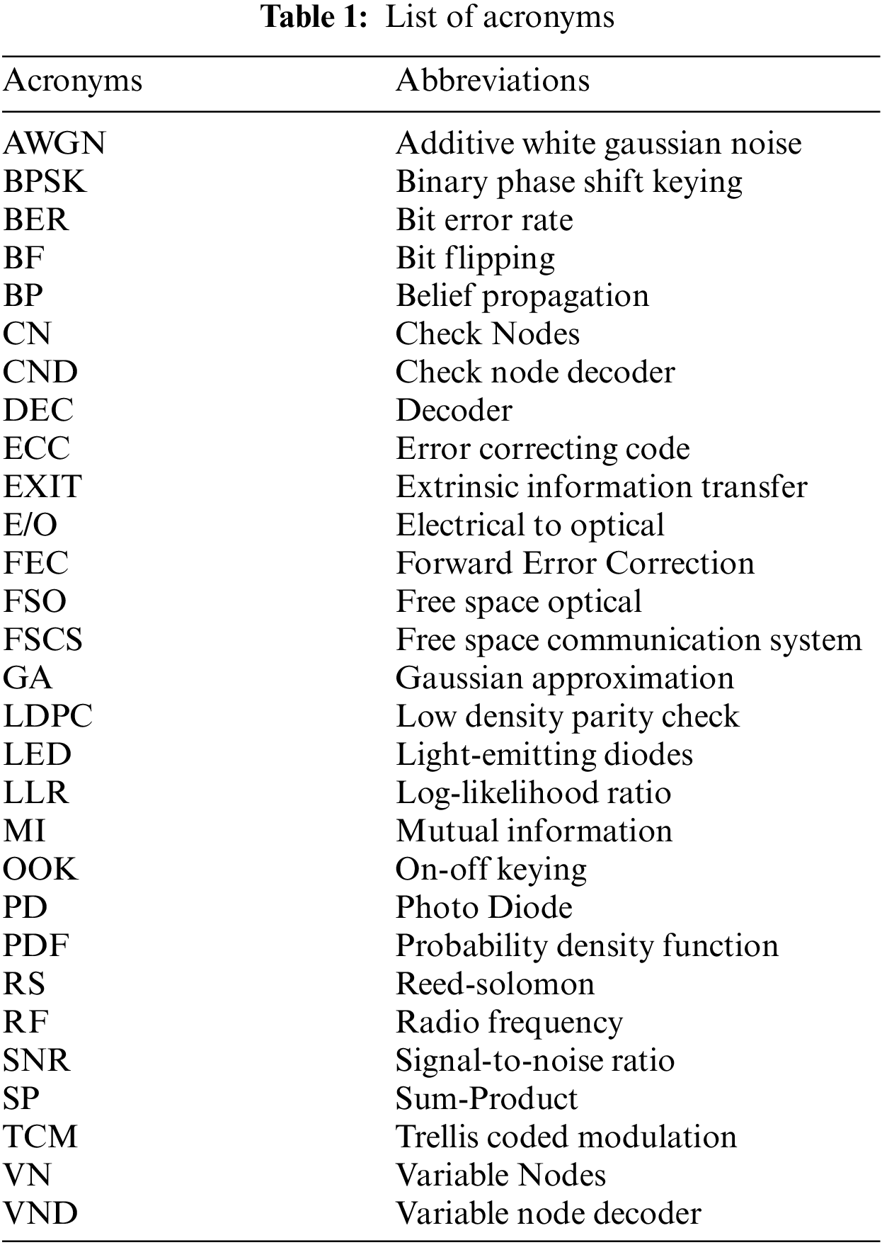
Error control coding has maximized the error correction capability of the optical link by using various forward error correction (FEC) methods consisting of convolutional codes, Reed-Solomon (RS) codes, Turbo codes, Trellis coded modulation (TCM), and LDPC. The study of error behavior using error correction codes within the fading channel has been a research topic for several years [2]. LDPC codes are preferable to turbo codes for terribly high-rate transmission due to their lower decoding complexity and computation time. The variable rate of LDPC codes can maximize the link capability and offer accurate coding gain [3]. Different assessments have been made for using LDPC codes in systems [4,5]. A complete list of acronyms is provided in Tab. 1.
Gallager developed LDPC codes in 1960 [4]. These codes belong to a specific class of Shannon-capacity approaching codes. Gallager’s work was overlooked for twenty years. In 1981, Tanner worked on LDPC codes and used graphs to represent LDPC codes. Later in the 1990s, David Mackay relieved Tanner’s work [5]. Long LDPC codes decoded by belief propagation are closer to Shannon’s theoretical limit. Due to this advantage, LDPC codes are strong competitors over other codes used in a communication system, such as turbo codes. LDPC is the basic example of ECC, which has become very famous as it achieves near Shannon capacity in the additive white Gaussian noise (AWGN) [6]. LDPC codes have parallelism features supporting various speeds, performances, and memory consumption [7]. LDPC codes are easy to design with code rate and block length, and also, the rate adaptability can be easily achieved in LDPC codes. Extrinsic information transfer (EXIT) is a simple technique to show LDPC code convergence behavior. EXIT analysis is an efficient tool for designing the iterative decoding system [8]. EXIT chart comprises two components decoder, which is variable node decoder (VND) and Check node decoder (CND) [9].
In this paper, we first consider a regular binary code, and then an irregular LDPC code is evaluated. Evaluation of the LDPC code threshold with a certain degree distribution is vital for designing a coding system approaching the Shannon limit. But it is complicated to optimize degree distribution direct using density evolution due to its exhaustive calculations. Alternatively, using Gaussian approximation (GA) of the message densities for both regular and irregular LDPC codes is very simple. For LDPC, EXIT charts are used to evaluate the sum-product Algorithm. This paper optimized the codes by applying curve-fitting on EXIT charts. Thus, the analysis of EXIT charts predicts an optimistic value for the convergence threshold. LDPC code gives exceptional BER performance nearly close to the Shannon limit. We also computed the BER by soft decision and compared it to the proposed FSCS.
The paper outline is as follows. In Section 2, we develop a system model under consideration. We formalize the LDPC code with factor graph and decoding algorithms in Section 3. In Section 4, we also introduce the LDPC code notations. Section 5 also introduces the code convergence measuring tools useful for following analysis and EXIT chart behavior in the proposed system. In Section 6, we present some numerical results. Section 7 concludes the proposed research work.
The proposed free-space communication system (FSCS) in which optical and radio channels are considered parallel is given in Fig. 1. It comprises two parallel RF and FSO channels with a transmitter (encoder) pair and a receiver (decoder). The modulating data is encoded into the codeword of
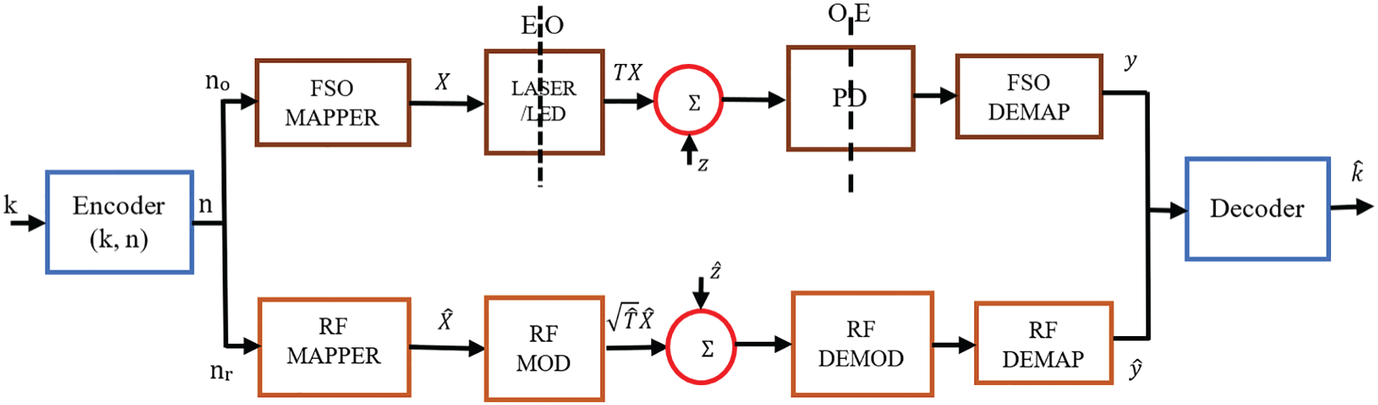
Figure 1: Block diagram of a proposed Free-Space Communication System (FSCS)
Binary mapping schemes are used on each link to map the channel bits. The mapped symbols of each channel are transmitted over the respective link. Thus, each stream from the encoder is mapped to create consistent RF and FSO symbols sent respectively on the particular link. The signal is modulated by RF link to a mmWave carrier frequency of RF, even though FSO link. The single encoder aims to minimize the computational complexity and the communication cost using a single pair of encoder and decoder having slow varying channels.
At the transmit side, codewords are mapped to channel symbols employing binary modulation schemes. The on-off keying (OOK) modulated optical signal comes from the transmitter. A simple signal model from the FSCS communication system over an optical link is given by, See Eq. (1)
where
Considering the RF power P, the received RF signal is expressed by
where
The Initial letter of each notional word in all headings is capitalized. LDPC code is most efficiently employed linear code along with a sparse parity check matrix (
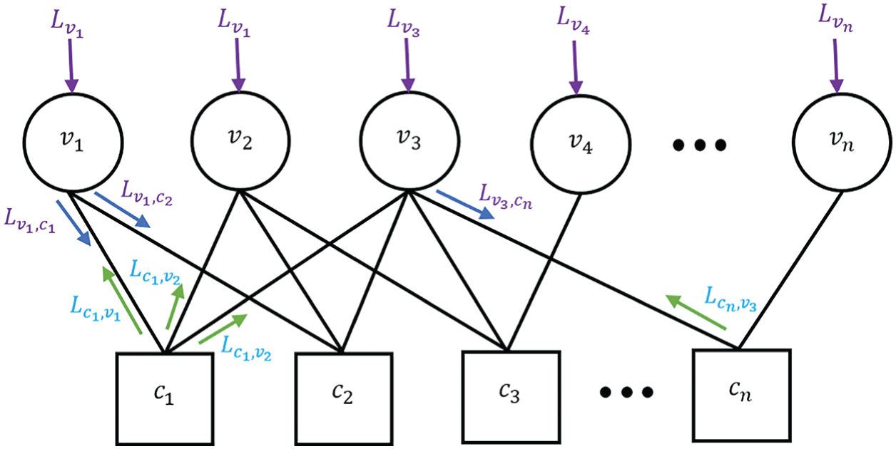
Figure 2: Parity check matrix factor graph
In LDPC code, Optical and RF channels are considered with various mapping schemes. In this case, the codeword is divided into two ways, which are optical and RF links.
where
where
where
3.1 Bit Flipping (BF) Algorithm
Gallager developed the Bit Flipping (BF) along with all the LDPC codes [12]. The Algorithm belongs to the group of iterative decoding algorithms and is primarily based upon a calculation of the syndrome vector in the parity matrix
3.2 Sum-Product (SP) Decoding Algorithm
The sum-product (SP) decoding is identical to the bit flipping decoding. The SP decoding algorithm is based on a soft decision [12]. However, in this case, the messages are now represented as soft values. In such a way, we can call the bit flipping decoding hard decision decoding; moreover, the SP decoding is denoted as soft-decision decoding [13]. The received probabilities are referred to as received bit prior probabilities.
4 LDPC Code Definitions and Notations
Recently LDPC codes have gained much attention in coding theory owing to their near Shannon capacity performance for many data transmission and storage channels. LDPC codes provide many other benefits, such as less computational complexity, and its decoding can be counted, so that correct decoding is detectable [13]. Variable nodes (VN) are designated by
where
where
For BPSK
where
where
Subsequently, the channel is symmetric by supposing the entirely zero codewords are transmitted when analyzing the decoding algorithm. The channel information’s probability density function (PDF) is Gaussian sufficient for the following symmetry situation.
The researchers evidenced that the situation is gratified for channel messages after symmetry. For all of the values, the identity is preserved in following iterations within the sum-product interpreting set of rules [14]. Let
The PDF is symmetrical, and it is supposed that all zero codewords are transmitted [14],
where
EXIT chart was made-up to investigate the code convergence behavior [9]. The convergence behavior of the LDPC code is analyzed by employing the EXIT chart. A much-detailed analysis of the EXIT charts and the EXIT functions’ evaluation over each CV and VN is given in [16]. The EXIT function is designed by modeling the soft values over each node are also provided in [16]. This paper presents two techniques such as curve fitting and regular LDPC code.
In the curve-fitting technique, analysis is applied by the fitting optimization functions
By optimizing, we can design better codes for the projected threshold. The look-up table (curve fitting) has created two codes with the same parameters. In Tab. 2, the code parameters are specified. The transfer curves are very intently similar. Therefore, the projected convergence threshold is
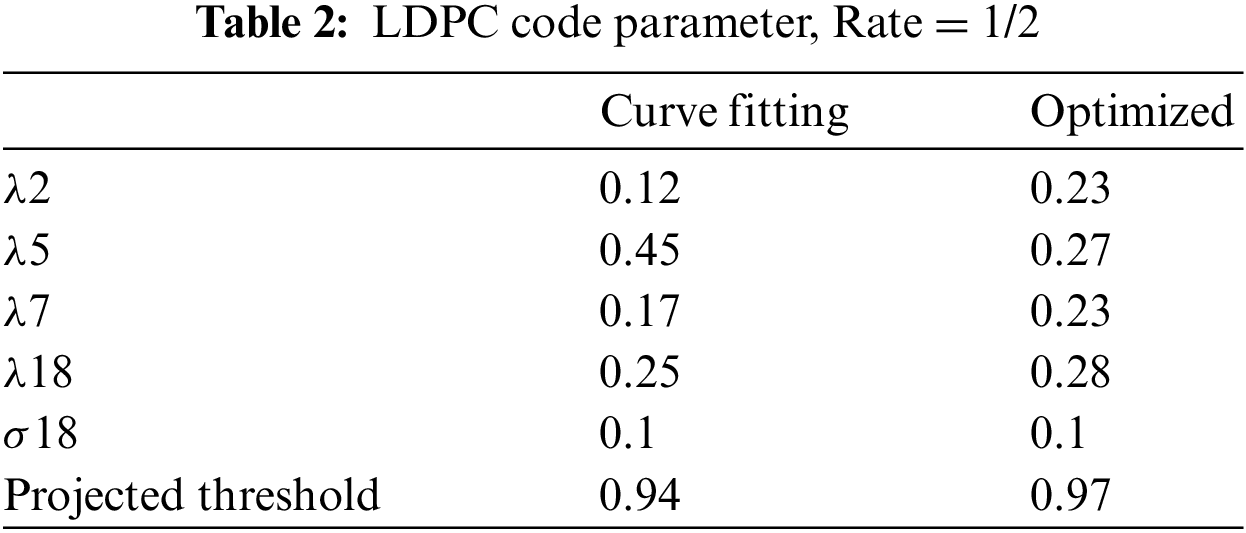
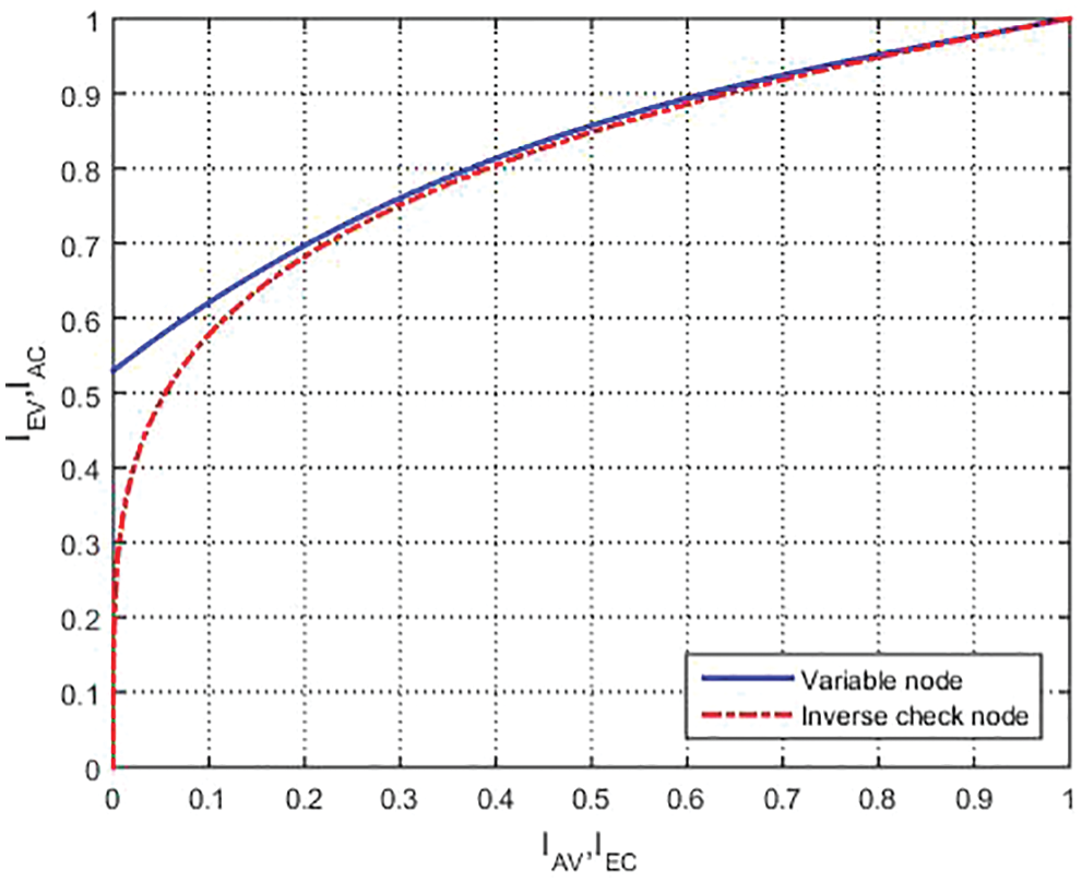
Figure 3: EXIT chart by using curve fitting technique
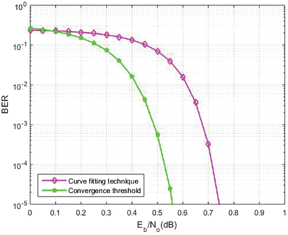
Figure 4: BER comparison between curve fitting technique and convergence threshold
The division of the output messages of CNs is not always assumed to be a Gaussian symmetry [6]. The VN detector of the EXIT function is evaluated to analyze the CNs information using a normal histogram. The failure of the VN detector optimization function owing to the defined approximation can be ignored. Assuming
The decoding operation of a CN is comparable to it of one single parity check code. The distribution of messages from VNs to test nodes but independent and identically distributed (i.i.d) inputs are transmitted to the VNs [6]. If
For regular LDPC codes, σi2 the output messages are evaluated by,
In [6], due to the variable nodes of numerous degrees, the distribution of variable nodes is a symmetric Gaussian mixture for the output messages.
The variable node detector of the EXIT function is given as
The CN decoder EXIT function is [14],
We display that this calculation results in a better EXIT curve for the check node detector than the actual function. As an anticipated result, the thresholds for convergence are improved than the actual values.
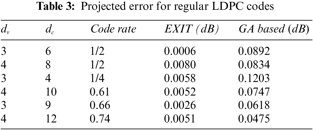
In Figs. 5 and 6, it shows the simulation results obtained using the EXIT technique considering the regular and irregular LDPC code with
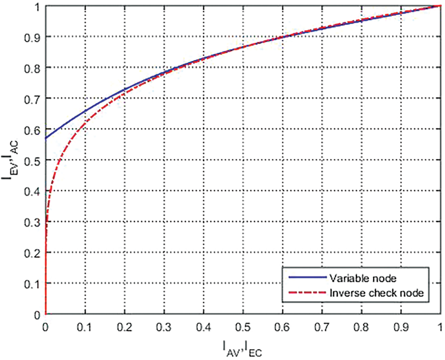
Figure 5: EXIT chart for regular LDPC codes
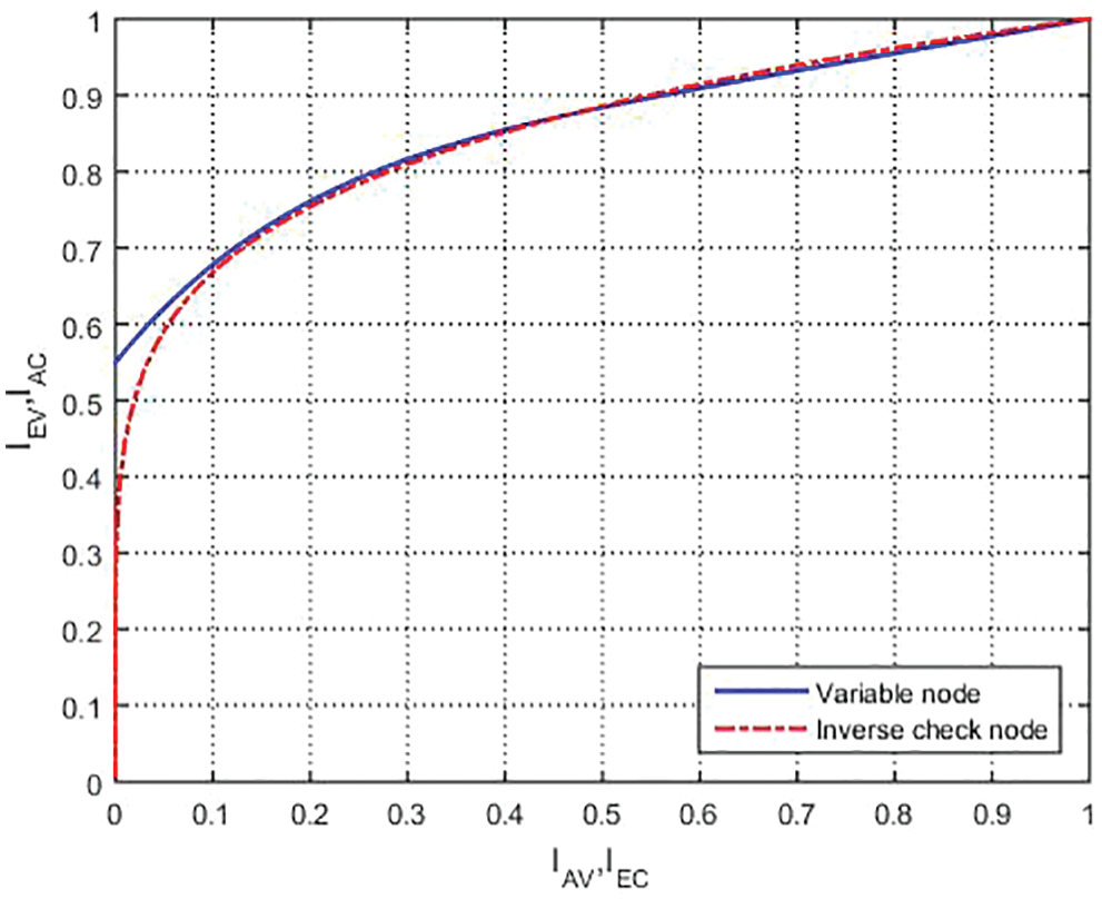
Figure 6: EXIT chart for irregular LDPC codes
In Fig. 7, it is shown that we conduct the number of iterations to analyze the bit error rate (BER) performance based on
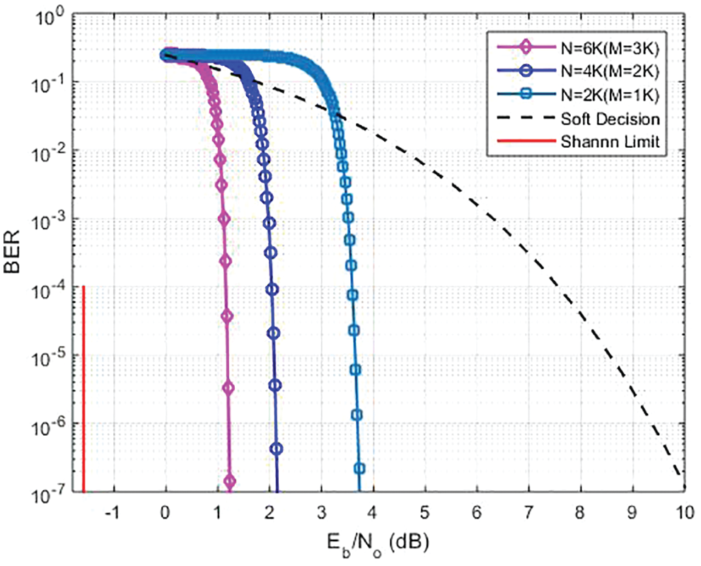
Figure 7: BER performance at different M
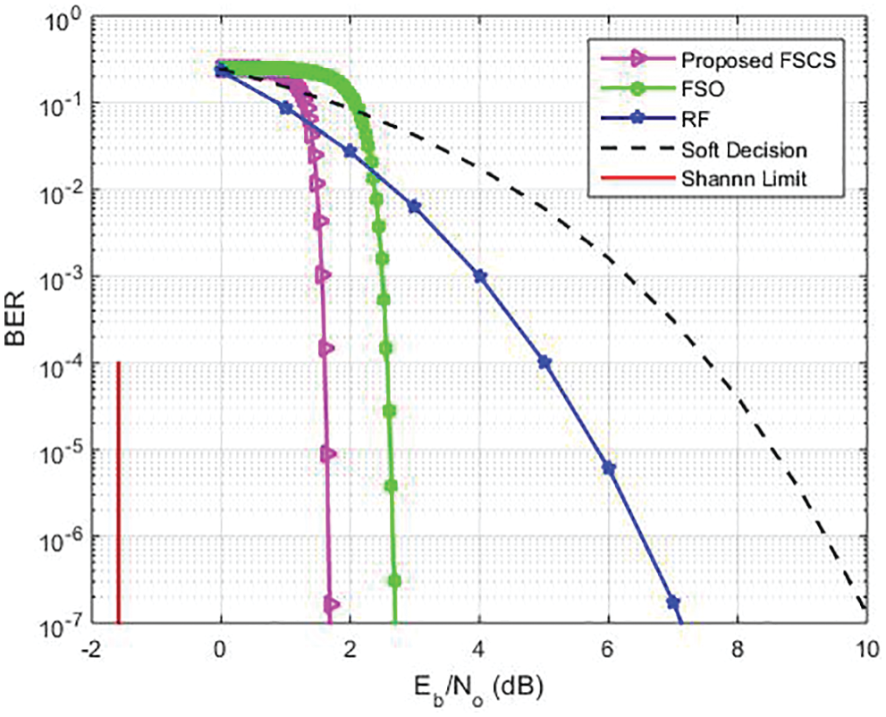
Figure 8: Comparison of our proposed FSCS at the same M
The proposed research work analyzes the curve-fitting approach to developing the LDPC codes. The optimization technique is also developed and is solely based on a convergence criterion that gives better results. The primitive principles of code design tools and the EXIT chart for FSCS are outlined. This work provides a vision of the performance of the proposed system for regular LDPC code and shows how the BER performance of FSCS links may be improved. It is observed that the presented work is well adapted to a range of decoding algorithms. The simulation results for the LDPC code indicate that the SP algorithm is optimal since its BER is stable and low for the bit flipping over given iterations. We also analyze the BER and investigate the performance of OOK and BPSK modulation schemes. We computed the LLR mapping, OOK and BPSK have been derived. From the simulation results, it is seen that our proposed FSCS is better than FSO and RF.
Funding Statement: The authors received no specific funding for this study.
Conflicts of Interest: The authors declare they have no conflicts of interest to report regarding the present study.
References
1. Z. Ghassemlooy, W. Popoola and S. Rajbhandari, Optical Wireless Communications: System and Channel Modelling with Matlab. Boca Raton, Florida, USA: CRC press, 2017. [Google Scholar]
2. J. Hagenauer and E. Lutz, “Forward error correction coding for fading compensation in mobile satellite channels,” IEEE Journal on Selected Areas in Communications, vol. 5, no. 2, pp. 215–225, 1987. [Google Scholar]
3. C. Fewer, M. Flanagan and A. Fagan, “A versatile variable rate LDPC codec architecture,” IEEE Transactions on Circuits and Systems I: Regular Papers, vol. 54, no. 10, pp. 2240–2251, 2007. [Google Scholar]
4. R. G. Gallager, “Low density parity check codes,” IEEE Transactions on Information Theory, vol. 10, no. 2, pp. 172, 1964. [Google Scholar]
5. D. J. C. MacKay and R. M. Neal, “Near shannon limit performance of low density parity check codes,” Electronics Letters, vol. 33, no. 6, pp. 457–458, 1997. [Google Scholar]
6. S. Garg, A. Dixit and V. Jain, “Analysis of LDPC codes in FSO communication system under fast fading channel conditions,” IEEE Open Journal of Communications Society, vol. 2, pp. 1663–1673, 2021. [Google Scholar]
7. Z. Zhang, L. Zhou and Z. H. Zhou, “Design of a parallel decoding method for LDPC code generated via primitive polynomial,” Electronics MDPI, vol. 10, no. 4, pp. 425, 2021. [Google Scholar]
8. H. Bao, C. Zhang and S. Gao, “Design and analysis of joint source-channel code system with fixed-length code,” Information MDPI, vol. 13, no. 6, pp. 281, 2022. [Google Scholar]
9. H. Kashif and M. N. Khan, “Future of free space communication systems (FSCSAn overview,” in Intermountain Engineering, Technology and Computing (IETC), Utah Valley University Orem, USA, pp. 1–5, 2020. [Google Scholar]
10. R. G. Gallager, “Low-density parity-check codes,” IEEE Transaction on Information Theory, vol. 8, no. 1, pp. 21–28, 1962. [Google Scholar]
11. T. Richardson and R. L. Urbanke, “The capacity of low-density parity check codes under message-passing decoding,” IEEE Transactions on Information Theory, vol. 47, no. 2, pp. 599–618, 2001. [Google Scholar]
12. F. R. Kschischang, B. J. Frey and H. A. Loeliger, “Factor graphs and the sum-product algorithm,” IEEE Transactions on Information Theory, vol. 47, no. 2, pp. 498–519, 2001. [Google Scholar]
13. M. N. Khan and M. Jamil, “EXIT chart behaviour for the hybrid FSO/RF communication system,” in Int. Conf. on Information, Communications and Signal Processing (ICICS), Singapore, 2015. [Google Scholar]
14. T. J. Richardson, M. A. Shokrollahi and R. L. Urbanke, “Design of capacity approaching irregular low-density parity-check codes,” IEEE Transactions on Information Theory, vol. 47, no. 2, pp. 619–637, 2001. [Google Scholar]
15. M. N. Khan, S. O. Gilani, M. Jamil, A. Rafay, Q. Awais et al., “Maximizing throughput of hybrid FSO-RF communication system: An algorithm,” IEEE Access, vol. 6, pp. 30039–30048, 2018. [Google Scholar]
16. M. N. Khan, M. Jamil and M. Hussain, “Adaptation of hybrid FSO/RF communication system using puncturing technique,” Radio Engineering, vol. 25, no. 4, pp. 12–19, 2016. [Google Scholar]
17. A. Ashikhmin, G. Kramer and S. T. Brink, “Extrinsic information transfer functions: model and erasure channel properties,” IEEE Transactions on Information Theory, vol. 50, no. 11, pp. 2657–2673, 2004. [Google Scholar]
Cite This Article
 Copyright © 2023 The Author(s). Published by Tech Science Press.
This work is licensed under a Creative Commons Attribution 4.0 International License , which permits unrestricted use, distribution, and reproduction in any medium, provided the original work is properly cited.
 Downloads
 Citation Tools