
 Submit a Paper
 Propose a Special lssue
 Open Access
ARTICLE
Artificial Magnetic Conductor as Planar Antenna for 5G Evolution
1 College of Computing, Prince of Songkla University, Phuket Campus, 83120, Thailand
2 Faculty of Technical Education, Rajamangala University of Technology Isan, Khonkaen Campus, 40000, Thailand
3 Department of Electrical Engineering, Faculty of Engineering, Kasetsart University, 10900, Thailand
4 Research Center of Innovation Digital and Electromagnetic Technology, Department of Electrical and Computer Engineering, Faculty of Engineering, King Mongkut’s University of Technology North Bangkok, Bangkok, 10800, Thailand
5 School of Engineering, King Mongkut’s Institute of Technology Ladkrabang, Bangkok, 10520, Thailand
* Corresponding Author: Pracha Osklang. Email:
Computers, Materials & Continua 2023, 74(1), 503-522. https://doi.org/10.32604/cmc.2023.032427
Received 17 May 2022; Accepted 21 June 2022; Issue published 22 September 2022
 View Full Text
 Download PDF
Abstract
A 5G wireless system requests a high-performance compact antenna device. This research work aims to report the characterization and verification of the artificial magnetic conductor (AMC) metamaterial for a high-gain planar antenna. The configuration is formed by a double-side structure on an intrinsic dielectric slab. The 2-D periodic pattern as an impedance surface is mounted on the top surface, whereas at the bottom surface the ground plane with an inductive narrow aperture source is embedded. The characteristic of the resonant transmission is illustrated based on the electromagnetic virtual object of the AMC resonant structure to reveal the unique property of a magnetic material response. The characteristics of the AMC metamaterial and the planar antenna synthesis are investigated and verified by experiment using a low-cost FR4 dielectric material. The directional antenna gain is obviously enhanced by guiding a primary field radiation. The loss effect in a dielectric slab is essentially studied having an influence on antenna radiation. The verification shows a peak of the antenna gain around 9.7 dB at broadside which is improved by 6.2 dB in comparison with the primary aperture antenna without the AMC structure. The thin antenna profile of λ/37.5 is achieved at 10 GHz for 5G evolution. The emission property in an AMC structure herein contributes to the development of a low-profile and high-gain planar antenna for a compact wireless component.Keywords
The perfect magnetic conductor (PMC) is a duality of the perfect electric conductor (PEC) in electromagnetism, but it does not exist in nature. With the well-known principle of the high-impedance surface (HIS), the planar periodic surface theoretically gives the insight behind the artificial magnetic conductor (AMC) associates with the surface wave suppression along the media interface at the resonant frequency [1]. Based on the electrical modeling, the characteristic of high impedance is emerged at the resonant frequency band inductance and capacitance has represented each other as a function of frequency. The AMC structure is a type of metamaterials that imitate property of the PMC property at a certain frequency. Technically, the AMC metamaterial is engineered as a two-dimensional (2-D) metal-dielectric inclusion. The periodic surface behaved as a frequency selective surface can be a set of the sub-wavelength metallic elements as fundamental [2]. In that the dielectric slab is a host component to apply for the AMC formation which play a role in the EM activity between the periodic surface and ground plane.
In recent works [3–5], the compact AMC unit cell can be miniaturized by modifying the complicated geometrical resonator profile and the multiband operation are extremely investigated to gain more the EM ability. Most of the applications consist of the EM wave absorber development based on the loss effect in materials and the antenna applications enable the structural configuration for a low profile and radiation enhancement. The contribution of the AMC metamaterial offers the vital impact on EM research communities in designing the high-performance antenna applications. Its exotic property is for improving radiation performance which can control and guide a field propagation. There are twofold in applying the AMC metamaterials in order to reform the antenna structures.
First, the AMC metamaterial behaves as a grounded substrate or a total planar reflector which the single antenna element can be positioned with an extremely small gap for a radiation improvement [1,6–8]. With the unique property of the in-phase reflection, the proximity between the antenna element and AMC grounded substrate is obtained resulting in the constructive interference. However, the existing works of this, the excited field source is dealt with the external primary antenna in control of a distance and in an assembly based on a stacked structure.
Second, the resonant cavity antenna (RCA), also known as a Fabry-Perot resonator antenna and leaky-wave antenna, is comprised by a parallel-surface structure with an interior air medium. Conventionally, the RCA configuration is based on the interaction between the total reflector and partial reflective surface (PRS) with a certain distance separation. In that, the structure is modified for replacement of the total reflective surface using the AMC instead of the PEC surface leading to a low-profile configuration [9]. To consider a round-trip phase using the ray optics analysis, the separation can be reduced to a quarter wavelength. In addition, the RCA configuration can achieve a thin subwavelength separation between surfaces by tailoring the reflection phase both the AMC and PRS to satisfy the cavity resonance [10–12]. However, the degradation of the performance for a gain level and beam pattern is observed in the thin profile structure.
Due to the growth of the fifth generation (5G) wireless system, the types of antenna devices have subjected for the high-performance requirement [13]. The recent 5G antenna work has been proposed in a Sub-6 GHz band using a patch antenna with a metamaterial superstate, but it comes up with a bulky structure that is unsuited for a thin profile due to the air space as an antenna height [14]. The planar configuration has a physical benefit which contribute to the compact system integration. The classical patch antenna has been incorporated into the concentric configuration of the two-layer-ring-based metamaterial, but the lateral size increases [15]. For a band above 6 GHz , the planar aperture antenna design has been introduced using a substrate integrated waveguide (SIW) structure based on a periodic groove surface to support the 5G band (around 10 GHz), however the complex layer-based composition is considered [16]. Recent works of the planar antennas using the unusual patterns for a periodic surface with a primary aperture feeder have been proposed to operate for a broadband [17,18] and to support the circular polarization [19,20]. However, their works unaddressed the medium characteristics and material properties.
The aim in this paper is to characterize the emission mechanism using an FR4-based AMC structure for a class of a directive planar antenna at 10 GHz (part of the 5G evolution) consisting of (i) effect of the absorption, (ii) transmission resonance, (iii) response of material property and (iv) characteristics of high-gain planar antennas. We emphasize to report a configuration of the simple AMC metamaterial to form the high-performance planar antenna by embedding primary excited source. The AMC metamaterial planar antenna is based on a low-profile structure as shown in Fig. 1. The double-side structure consists of the 5 × 5 uniform patch array on the top as shown in Fig. 1a and the short-end coplanar waveguide (CPW)-fed aperture as presented in Fig. 1b. Fig. 1c shows the isometric view of the proposed planar antenna structure using the cost effective FR4 dielectric slab. The rest of the AMC metamaterial and planar antenna configuration are characterized and illustrated in detail. The properties of an AMC metamaterial are provided in Section 2. The implementation of an planar AMC metamaterial antenna is then described in Section 3. The Section 4 reports the characteristics of the fabricated antenna prototype. In Section 5, we summarize the investigation and characteristics of the AMC metamaterial antenna.
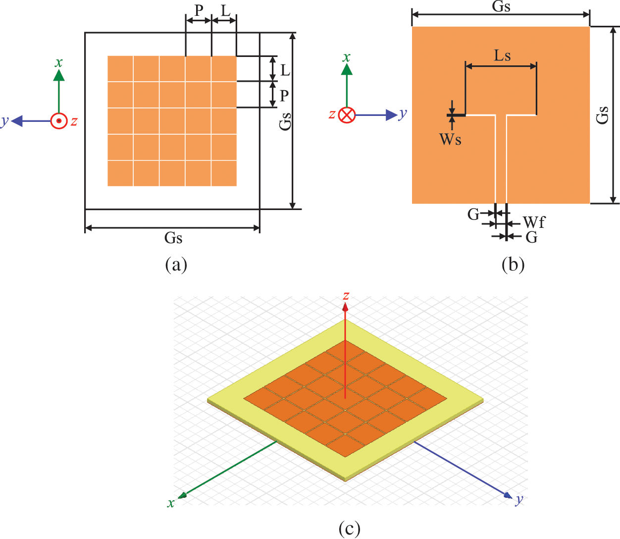
Figure 1: Layouts of the proposed planar AMC metamaterial antenna (a) the top view, (b) the bottom view and (c) the perspective view
2 Patch-Based AMC Metamaterials
The unit-cell structure is based on a patch-based AMC configuration. The investigation is performed to understand the characteristics. The AMC metamaterial can be typically formed by a thin resonant cavity associated the Fabry-Perot resonator. To examine the cavity resonance condition, the roundtrip phase difference
where the parameter H is a thickness of a dielectric slab as a thin-cavity distance and the PEC reflection phase is a constant of 180 degree (π radian). Here, the unit cell is represented as a sandwich structure using a double-side surface on a thin dielectric slab in a periodic boundary condition as shown in Fig. 2a.
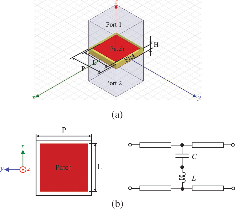
Figure 2: (a) Snapshot of the unit cell modelled in a periodic boundary condition for the EM simulation with the wave excitation as the port 1 and port 2 (b) the equivalent circuit of the patch element
The square patch element in a unit cell is selected due to a fundamental structure for an elementary resonator with less sensitive polarization. It can be represented as an equivalent circuit consisting of the series components of capacitance (C) and inductance (L) as shown in Fig. 2b. The metallic resonant square patch elements in a subwavelength mounted on the top and a blank metallic ground surface at the bottom. The dielectric slab plays a role in a cavity medium with a property of the reflection between two surfaces. In operation, the incoming field interacts with the patch element on the top that the reflection coefficient is examined to obtain the PMC characteristics which provide a total reflection magnitude and zero reflection phase. Here, the full-wave EM simulation used to investigate the AMC metamaterial was performed based on the Floquet theorem using the Ansys HFSS software to obtain the AMC response around the target frequency of 10 GHz (λ = 30 mm)–the frequency range 3 is part of the band spectrum for 5G evolution and 6G [21]. The unit-cell investigation was modelled to set the infinitive array environment. In this work, the low-cost commercial FR4 dielectric material was used to form the AMC metamaterial which has the relative permittivity and loss tangent of 4.4 and 0.025, respectively. Even if having a high loss tangent, the advantage of utilizing a FR4 material is realized for the cost-effective as commercial material in a standard process for the printed circuit broad (PCB) manufacturing. As recently proposed in Reference [22], using the FR4 material at the millimeter-wave frequency (∼28 GHz) has been challenged for an antenna design. The design dimension of the patch length (L) and the array period (P) are denoted as a unit cell geometry. The thickness (H) of the FR4 dielectric slab of 0.8 mm (∼λ/37.5) as available was selected for a thin profile.
2.2 Characteristics of Unit-Cell
In order to investigate the AMC characteristics, the parametric study was performed by varying the values of the patch length between 4.5 and 5.0 mm while maintaining the array period of 5.2 mm (∼0.36
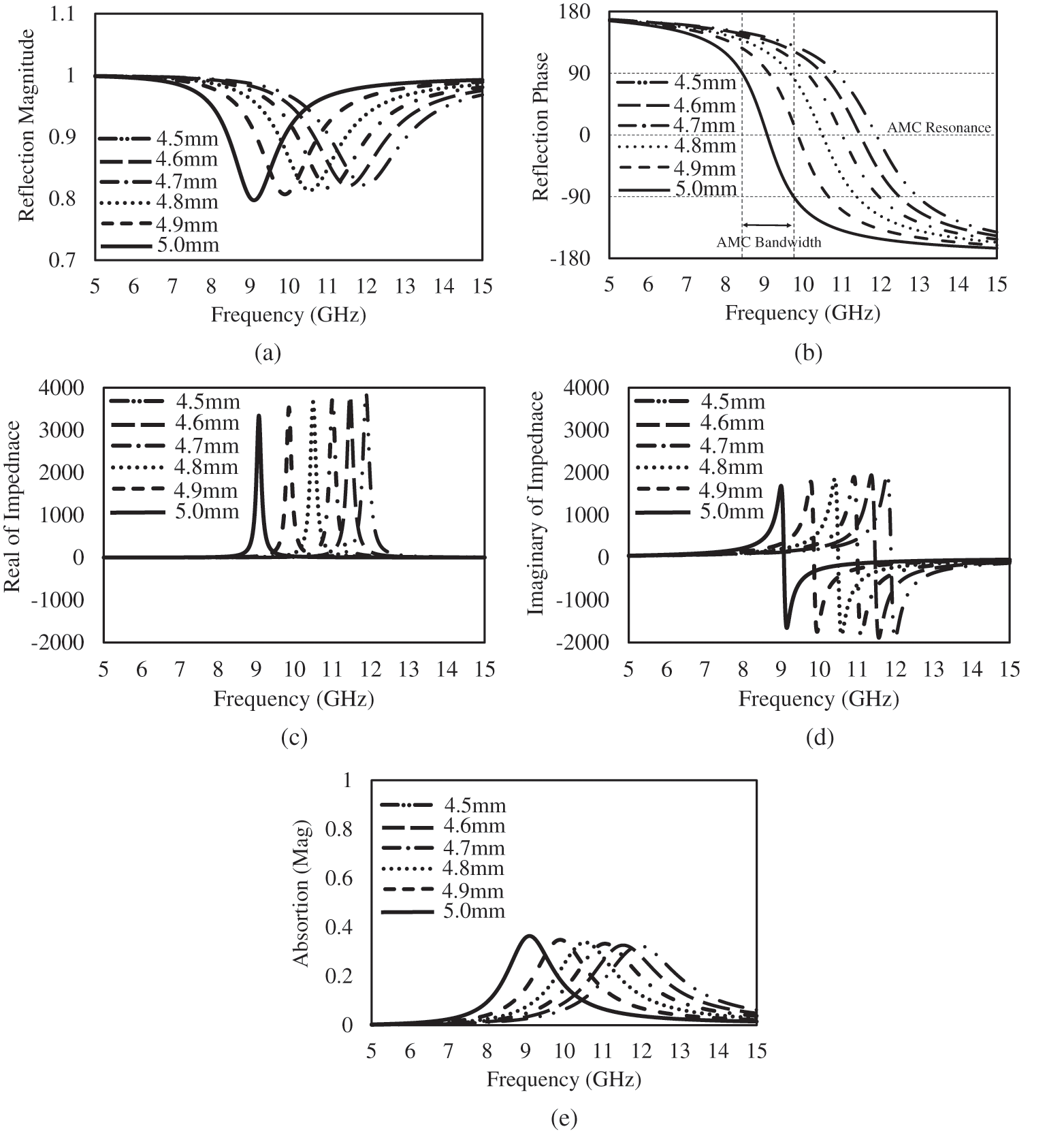
Figure 3: Simulated results of the characteristics (a) magnitude and (b) phase of the reflection coefficient; (c) resistance (real part) and (d) reactance (imaginary part) of the impedance; and (e) absorption in varying the lengths of the square patch from 4.5 to 5.0 mm by maintaining the period (P) of 5.2 mm
2.3 Surface Current and Field Characteristics in Unit Cell
The surface current distribution was simulated to understand the EM activity in the selected case of the parameter P = 5.2 mm and L = 5.0 mm, which the AMC resonance occurs at 9.1 GHz. Fig. 4a shows the profile of the surface current magnitude on the top of the dielectric slab (the patch position). At the resonant frequency, the induced surface current illustrates that the high magnitude is maximum at the center, and it is slightly lower to zero both the patch edges (the small gap between a patch array) along the excited electric-field direction. Fig. 4b presents the EM mirror effect of the surface current magnitude generated on the ground plane that the profile is corresponding to the characteristic of the surface current on the top. Fig. 4c also exhibits the vector profile of the surface current on the unit-cell structure of the dielectric slab in the isometric view. It reports that the anti-phase current configuration depicts between the top and the bottom surfaces. Therefore, the manifestation of the surface current configuration in the AMC metamaterial is corresponding to the EM mechanism with the transmission resonance based on the coupled surface plasmon polaritons for the light manipulation in Reference [24].
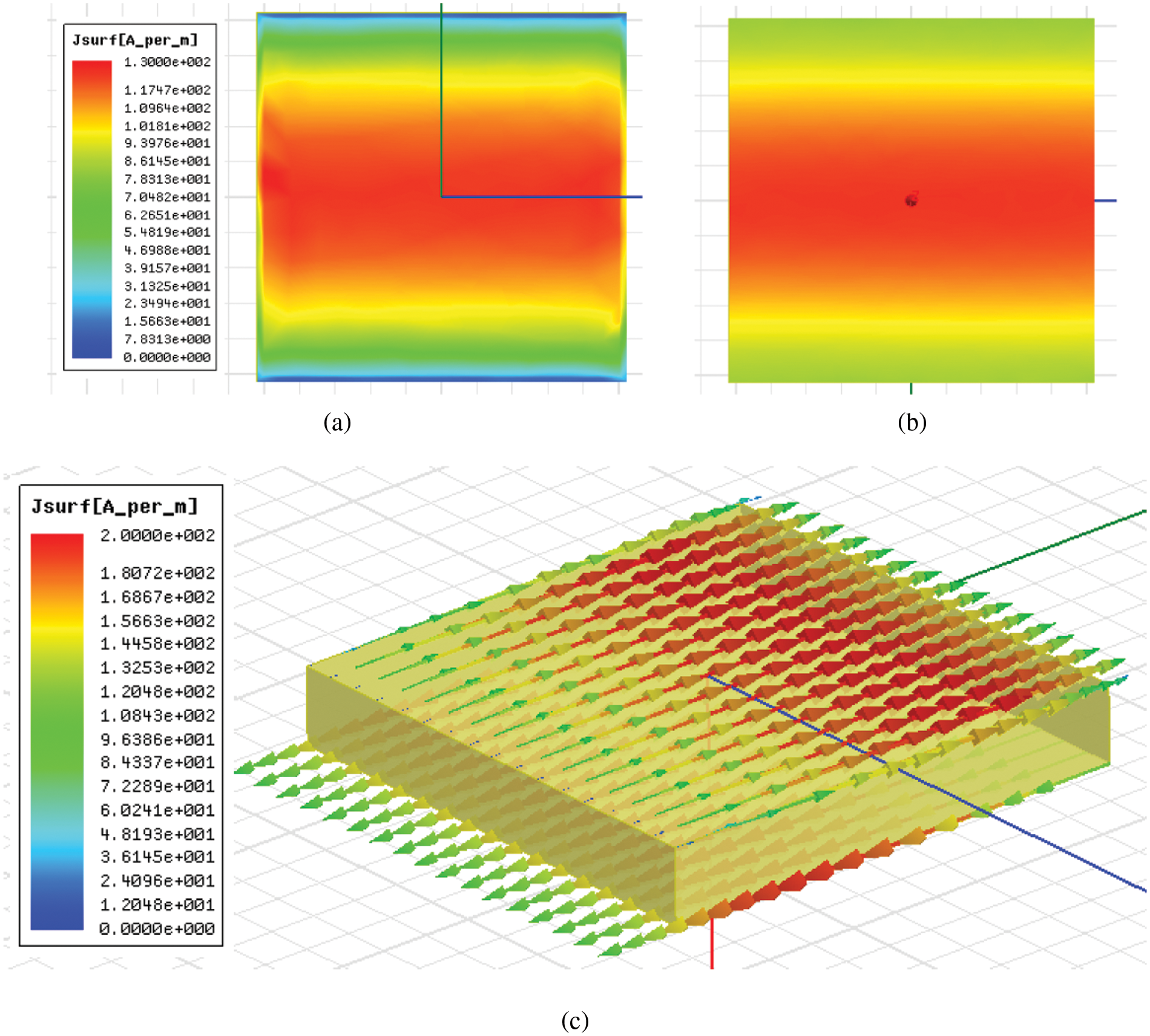
Figure 4: Snapshots of the current distribution of the unit cell of the AMC metamaterial structure at the AMC resonant frequency of 9.1 GHz; (a) the surface current magnitude on the top, (b) the surface current magnitude at the bottom and (c) the profile of the vector surface current both the top and bottom surfaces (patch and ground in the inactive view)
To visualize the EM field effect in artificial media, the AMC unit cell was simulated to illustrate the electric (E) and magnetic (H) response in the FR4 dielectric slab. Fig. 5 shows the EM field plot of the magnitudes at the AMC resonance at 9.1 GHz. The field effect is corresponding to the characteristics of the anti-phase current configuration in Fig. 4c. It can be observed that the electric (E) field is very weak occurred in the dielectric slab, but the fringing effect occur around the patch edge to interact with the neighbor patches as shown in Fig. 5a. On another hand, the magnetic (H) field is very strong in the dielectric slab which is influenced by the coupling effect of the induced surface currents on the top and bottom as shown in Fig. 5b. As a result, the EM field activities reveal the characteristic the high magnetic response in the hosted FR4 dielectric medium between the actual resonant patch element and the virtual patch on the ground surface.
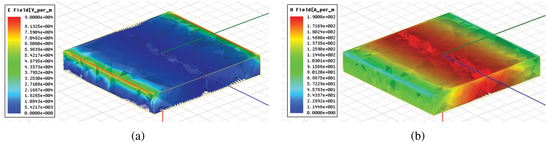
Figure 5: Snapshots of the current distribution of the unit cell of the AMC metamaterial structure at the AMC resonant frequency of 9.1 GHz; (a) the surface current magnitude on the top, (b) the surface current magnitude at the bottom and the profile of the vector surface current both the top and bottom surfaces (patch and ground in the inactive view)
2.4 Transmission Resonance and Material Characterization
With two periodic surfaces as a resonant structure, the physical model of the AMC metamaterial can be reformed to characterize the material properties. The EM image theory can be applied to model the virtual element in place of the ground surface as a symmetry plane [25]. The periodic surface as an identical patch array is replaced instead of the ground surface acted as a mirror plane with the distance in an opposite direction of the actual patch array on the top. Here the unit-cell structure is modified by increasing the thickness of the FR4 dielectric slab from 0.8 to 1.6 mm and positioning the identical patch elements at the bottom surface of the FR4 dielectric slab. It is seen that the 3D structural model of the modified unit cells as identical surfaces is also associated with the Fabry-Perot cavity principle. The reflection (S11) and transmission (S21) are obtained by the two-port unit-cell simulation in a normal incidence which is like in Fig. 2. The excited field propagates via the unit-cell structure providing the reflection and transmission responses. Then, the material properties of the electric permittivity (ε) and magnetic permeability (μ) are determined by means of the retrieve method based on responses of the resultant scattering parameters using Eq. (2) through (5) [26,27]. The refraction index (n) and wave impedance (z) are calculated by obtaining the reflection (S11) and transmission (S21). The parameter k and d are expressed as a wave number and thickness (H) of a dielectric slab.
In addition, the effect of the dielectric loss is considered in this investigation process for the material characteristics as aforementioned. Hence, the comparative study is illustrated in detail between the FR4 lossy and lossless property. Fig. 6a shows the simulated reflection and transmission of the modified unit cell both magnitude and phase component in a case of the selected parameter P = 5.2 mm and L = 5.0 mm. It reveals that the transmission resonance is emerged at the frequency of 9.6 GHz close to the AMC response. The line-shape profiles are similar both study cases of the different loss parameters in an ordinary dielectric material. However, the distinction of the loss effect in the dielectric indicates that the transmission peak and reflection dip are imperfect to unity and zero, respectively. The phase shift response of the reflection is occurred at 9.6 GHz whereas the transition phase of the transmission is turned at 9.8 GHz as shown in Fig. 6b. Fig. 7 exhibits the response of the complex electric permittivity (ε) and magnetic permeability (μ) over 5–15 GHz. The remarkable characteristic is at the peak of the resonant transmission. It indicates the electric permittivity close to zero (ε = 0) and the magnetic permeability extremally high. However, the effect of the dielectric loss properties dominates the imperfect of the zero electric permittivity, and the peak of the magnetic permeability response is reduced in the term of the amplitude. In that the imperfect of the resonant transmission gives a rounded feature at a location of the resonant frequency.
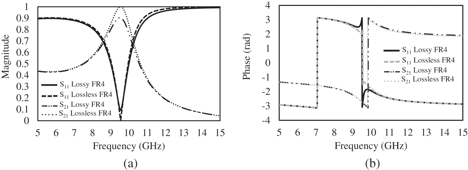
Figure 6: Simulated results of the unit cell of the two-layer identical patch elements consisting of: (a) the magnitude (b) phase of transmission (S21) and reflection (S11) between the lossy and lossless parameters
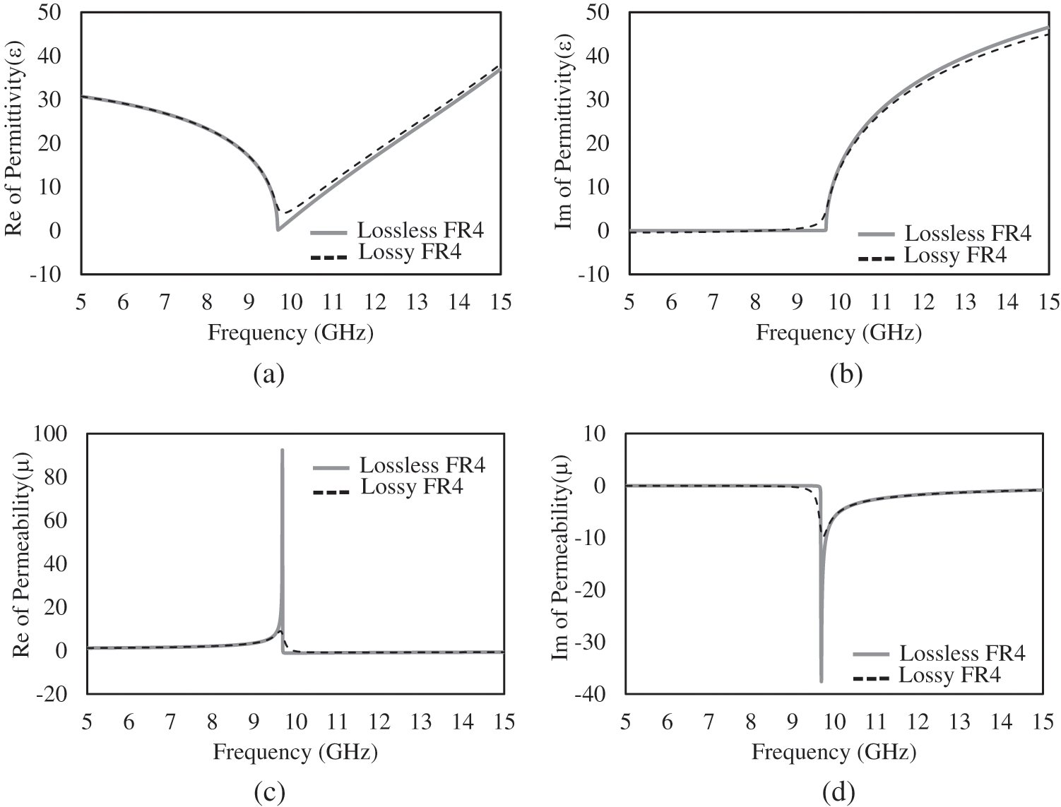
Figure 7: Response of the complex properties of the metamaterial, (a) the real part and (b) the imaginary part of the electric permittivity (ε), and (c) the real part and (d) the imaginary part of the magnetic permeability (μ) between the lossy and lossless parameters
3 Synthesis of AMC Metamaterial Planar Antennas
The AMC metamaterial is employed to implement the high-gain planar antenna in this section. The narrow aperture element is incorporated into the AMC metamaterial to form the antenna configuration. Using the coplanar waveguide (CPW) to connect to the aperture resonator, the planar feeder provides a simple profile structure with the slotting technique as presented in Fig. 1. It benefits that the primary feeder source can be embedded into a ground surface of the AMC metamaterial. The short-end CPW interface is considered as an inductive feeder mechanism. The narrow aperture resonator has a target frequency operation at 10 GHz which the determination of the physical parameters is depended on the aperture length (Ls) and width (Ws). With the analysis in Reference [28], the aperture impedance (ZA) has a connection to the impedance (ZD) of a dipole strip (complementary version) as referred to Reference [29]. The relation can be written as
where the parameter
Here, the parameter Ls is determined around one wavelength and the parameter Ws is initially approximated as the one-tenth. The CPW feedline is determined based on the 50-Ω characteristic impedance that the design parameters consist of the width (Wf) and gap (G) as detailed in Reference [30]. The CPW feedline connected with the aperture by a short-end interface provides the characteristic of resonance. The position of the aperture element is vertically aligned at the center of the patch array of that AMC structure. To perform the parametric study, the response of input impedance indicates the resonances of a primary aperture as plotted in Fig. 8. With maintaining the parameter Ws = 0.3 mm, the parameter Ls is varied resulting in the resonant frequencies of the primary aperture at 10.85 GHz (Ls = 12.0 mm), 10.6 GHz (Ls = 13.0 mm), 10.35 GHz (Ls = 14.0 mm), 10.15 GHz (Ls = 15.0 mm) and 9.5 GHz (Ls = 16.0 mm). To tune the parameter Ws with maintaining the parameter Ls = 14.0 mm, the effect of the aperture resonance is dominated reporting at 10.2 GHz (Ws = 0.1 mm), 10.35 GHz (Ws = 0.3 mm), 10.5 GHz (Ws = 0.5 mm), 10.7 GHz (Ws = 1.0 mm) and 10.85 GHz (Ws = 1.5 mm). To realize the EM activity, the integration of the AMC structure and the CPW-fed aperture is involved to the mutual effect due to the nature both behaving as a resonator. The interaction between the AMC response and aperture radiator is considered as the coupling field connected to the mutual impedance. Therefore, the impedance matching in this antenna implementation is optimized by adjusting the aperture impedance which the parameter Ws can be tuned to satisfy the matching condition. The design dimensions are optimized to reach the high-performance antenna as listed in Tab. 1.

Figure 8: Response of the input impedance of the primary aperture, (a) the real part and (b) the imaginary part in cases of varying the parameter Ls between 12.0–16.0 mm, whereas (c) the real part and (d) the imaginary part in cases of varying the parameter Ws between 0.1–1.5 mm

Here, the antenna behavior is concerned in terms of the field interaction between the aperture response and the AMC operation. It is seen that the characteristic of the excited field in the primary aperture element is parabolic-like wavefront which is dissimilar to the plane wave in the unit-cell investigation. With this concern, the factor of the finite size of the patch array on the AMC structure is taken into account in a process of implementation. In the first steps, the finite-size patch array of the AMC metamaterial is studied to observe antenna performance consisting of the reflection and gain. Three study cases of the synthesized antenna are probed by varying the 2-D array dimensions of 4 × 4, 5 × 5 and 6 × 6 elements. To obtain the characteristics of antenna, the simulation work was carried out using the Ansys HFSS software package. The 3-D antenna structure is simulated to illustrate the characteristics of impedance and radiation.
Fig. 9 shows the simulated results of the reflection coefficient and the antenna gain as function of frequency over 8–12 GHz. As a result, the reflections have responses of the matching impedance around 10 GHz at which the small difference is affected by the surface impedance in the 2-D arrangement when increasing the array size. This factor can be primarily controlled by tuning the aperture impedance to achieve the impedance matching. To look at the antenna gain, the simulated responses show the radiation enhancement over the observed band, but it gives the small difference of the level and frequency location of the peak. The results of the gain peak and operation frequency is reported as: Case 4 × 4) 8.2 dB at 10.7 GHz; Case 5 × 5) 9.7 dB at 10.0 GHz; Case 6 × 6) 8.7 dB at 9.4 GHz. The frequency locations of the antenna peak are related to the AMC resonance, but it gives a small shift to the higher frequency when applying a small size due to the weak response taken in the array elements.
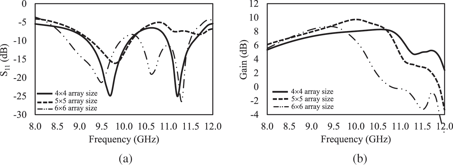
Figure 9: Simulated results of the AMC metamaterial-based antenna with varying the array size; (a) the reflection coefficient and (b) the antenna gains at the broadside as function of frequency
The radiation profile in the electric (E) and magnetic (H) plane at 10 GHz was simulated to characterize the radiation pattern between the antenna configuration with and without the patch array as shown in Fig. 10. The planar antenna without the patch array on the top is referred as a baseline which behaves as the traditional narrow aperture radiator to provide a bi-directional pattern both 0° (along the +z direction as a broadside) and 180° (along the −z direction as a backside). In a case of employing the patch array as the AMC metamaterial, the antenna mechanism is able to guide the wave propagation at the broadside and reduce the back radiation resulting in the directional pattern. It is evident that the AMC metamaterial take a control of the field radiation from the primary aperture element which the magnetic response can influence on the conductor surface.
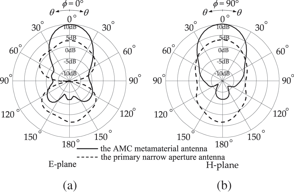
Figure 10: Simulated results of the radiation pattern in (a) the E plane and (b) H plane in a comparison with the primary narrow aperture antenna and the AMC metamaterial antenna
To investigate the dielectric loss effect in materials as aforementioned, the characteristic of the absorption behaves as a trapped-mode energy that can dominate performance of the radiation. Here, the antenna structure is simulated to study the ability of a radiation by employing the FR4 dielectric material with varying the dielectric loss tangent (tan δ). Fig. 11 shows the simulated results of the antenna gain as function of frequency in comparison with the other antenna cases consisting of the parameter tan δ = 0.02 (lossy case), 0.002 (low-loss case) and 0.0 (lossless case). The resultant gain peaks are obviously reported in the different levels of 9.7, 11.4, and 11.6 dB, respectively. It is known that the absorption around 36.5% reported for a lossy FR4 dielectric in Section 2 that dominates the gain attenuation around 2.0 dB in comparison with the lossless case (no absorbed energy).
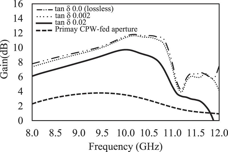
Figure 11: Simulated results of the AMC metamaterial-based antenna by varying the parameter of the dielectric loss including the tan δ = 0.02 (lossy case), 0.002 (low-loss case), 0.0 (lossless case) and the primary aperture (baseline)
To study the low-loss dielectric material, the peak is close to the lossless case that is significant in selection of dielectric materials in other high-quality dielectric types. Therefore, the property of a dielectric material is essential factor in design of a high-gain planar antenna using an AMC metamaterial. Furthermore, the resultant gain of the primary aperture antenna based on a lossy FR4 dielectric is included into the line plot that the peak of 3.5 dB is obtained at 10 GHz in the broadside radiation. It is evident that the characteristic of the radiation gain in the AMC metamaterial antenna can be improved by 6.2 dB at the broadside direction. To observe the profile of the radiation bandwidth of antenna performance, the frequency band response is connected to the transmission resonance in Fig. 6a.
3.4 Characteristics of Surface Current
Fig. 12 shows the magnitude of the surface current distribution consisting of the 0° and 90° phase of the excited field source at 10 GHz which are plotted on the top and at the bottom of the AMC metamaterial antenna. It reports that the surface current configuration associated with the mirror effect of the current characteristics in the AMC unit cell as aforementioned. The effect of the EM mirror can generate the current profile at the bottom which is similar to the appeared current on the array surface. To observe the entire antenna structure, the current distribution is non-uniform due to the wavefront characteristic of the excited field of the implemented antenna that is incompatible to the plane wave in the unit cell simulation. To realize the characteristic of the narrow aperture, the primary radiation behaves as a magnetic dipole. The synthesized antenna is also depended on a near-field factor due to the location of the primary field source which is internally positioned into the AMC metamaterial structure.
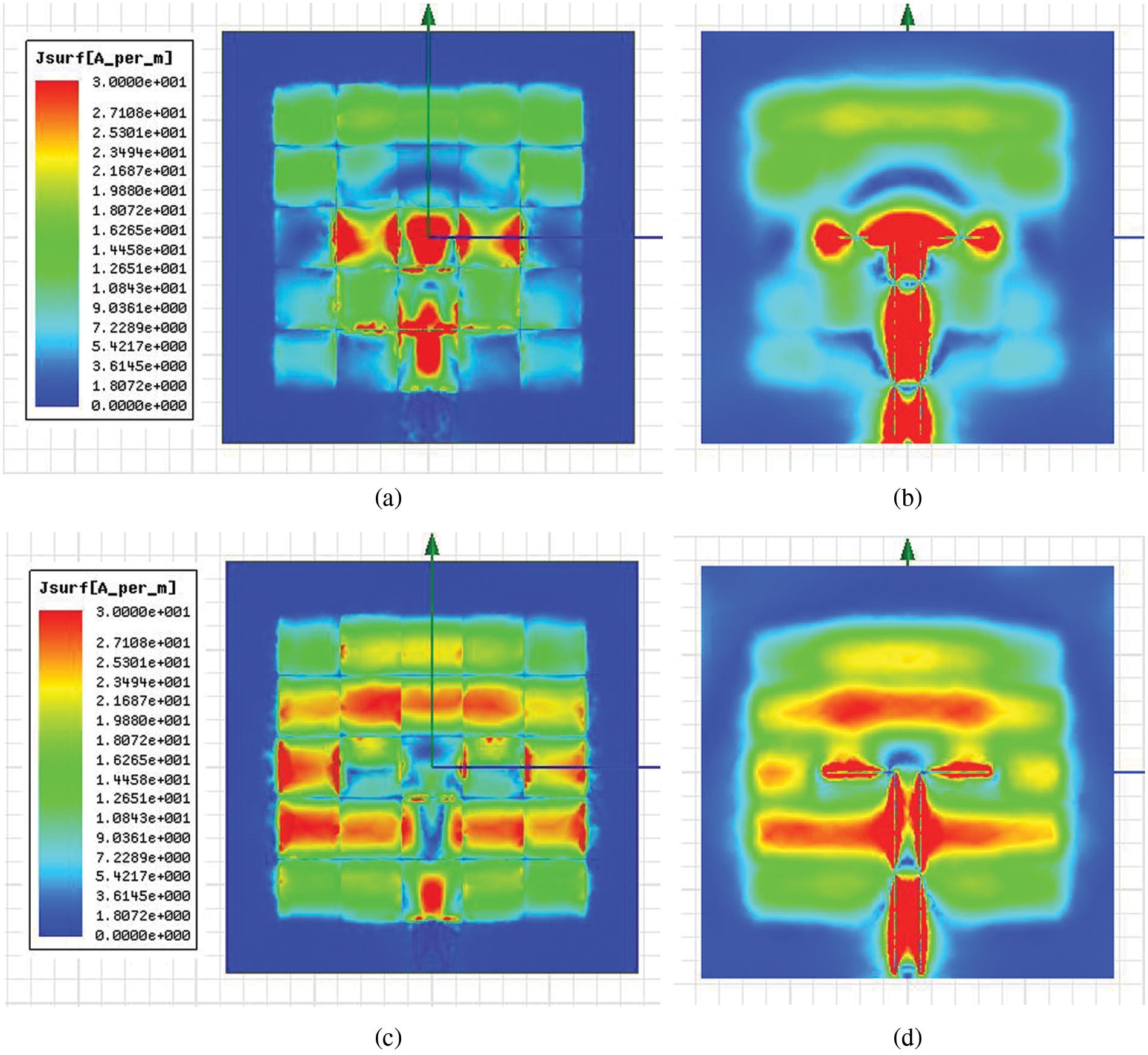
Figure 12: Snapshots of the surface current magnitude on the AMC metamaterial antenna at 10.0 GHz; (a) 0° phase plotted on the top surface, and (b) 0° phase plotted at the bottom, (c) 90° phase plotted on the top surface and (d) 90° phase plotted at the bottom surface
In this section, the prototype of the AMC metamaterial antenna design was produced based on a surface fabrication process of the print circuit board. The 0.8-mm-thick commercial FR4 board with a double-cladded copper was prepared as the target size. It is then cleaned and dried using a solution in the first steps. Next the designed layouts of the 5 × 5 patch array and the short-end CPW-fed aperture structure were patterned on the photomasks. Then the photoresist film was deposited on the copper surfaces and after that the pattern-transferred step was performed on the double-cladded copper of the prepared FR4 substrate by exposing the UV light. Next, the pattern-transferred FR4 substrate was developed using a solution to remove the exposed copper areas and to protect a layout of the antenna design-patterned parts. At the final step, the chemical etching process was performed to remove the unwanted copper surface. Figs. 13a and 13b show the top and bottom surfaces of the complete fabricated planar antenna on which the SMA connector was mounted to the CPW feedline and ground for an input signal energy.

Figure 13: Photographs of the fabricated AMC metamaterial-based antenna as (a) the 5 × 5 patch resonator array on the top surface and (b) the short-end CPW-fed aperture at the bottom surface
The test equipment in experiment is setup and calibrated in order to obtain the antenna characteristics including the reflection coefficient (S11) and the radiation gain. Fig. 14a shows the schematic set-up diagram based on the far-field measurement process. It was performed in the anechoic chamber consisting of the fabricated antenna as an antenna under test (AUT) and the standard horn antenna of the 73721 model with the R100 waveguide as a reference source. Both antennas were positioned and oriented on the supporter with a distance separation D = 30.0 cm. The Keysight vector network analyzer (model E5063A) is connected to provide a wave energy signal and obtain a frequency response through the port 1 and 2. The actual setup environment is shown in Fig. 14b which the two antennas are installed inside the anechoic chamber. The antenna gain measurement was determined based on the gain-transfer method to figure out the experimental result [31]. Fig. 15 exhibits the measured results as function of frequency over 8–12 GHz of the reflection (S11) and antenna gain. It reports that the matching impedance of the frequency operation and bandwidth of −10 dB are reported at 9.8 GHz and 800 MHz respectively. The antenna gain is 9.6 dB peaked at 10 GHz. It reveals that the well agreement between the experimental and simulated results is obtained in this measurement. The radiation profiles in the E- and H-plane pattern are measured and plotted at the frequency response of 10 GHz as shown in Fig. 16. It shows that the characteristic of a radiation provides the directional antenna of which the main lobe is at broadside with the low back lobe level. The side-lope level and the front-to-back ratio are reported of around 15.0 and 16.0 dB, respectively. Both the E- and H-plane patterns of the measured results are agreed well with the simulated outputs. It is evident that this antenna structure provides the characteristics of a high gain and directive property in employment of the AMC metamaterial.
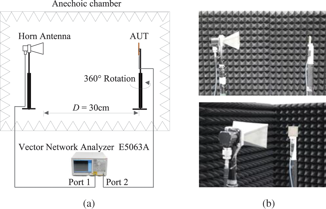
Figure 14: The measurement setup, (a) schematic set-up diagram and (b) photographs of the environment for the antenna measurement
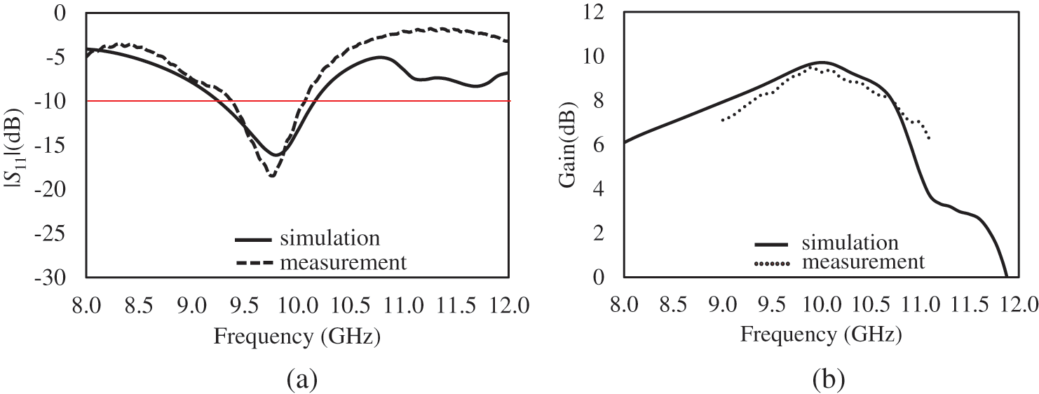
Figure 15: Measured results of the fabricated AMC metamaterial-based antenna; (a) the reflection coefficient and (b) the antenna gain at the broadside
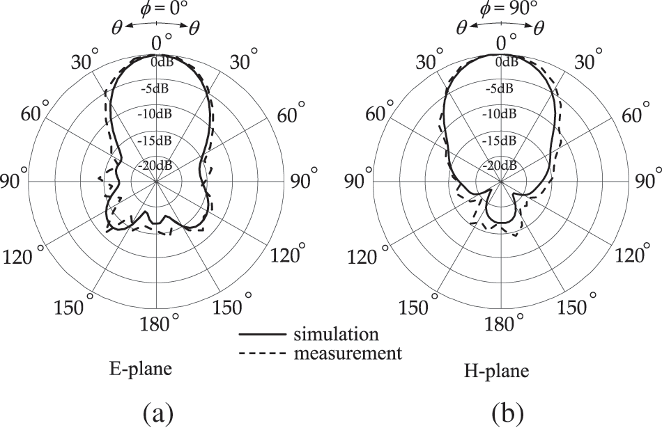
Figure 16: Measured results of the radiation pattern in (a) the E plane and (b) H plane in a comparison with the simulated results
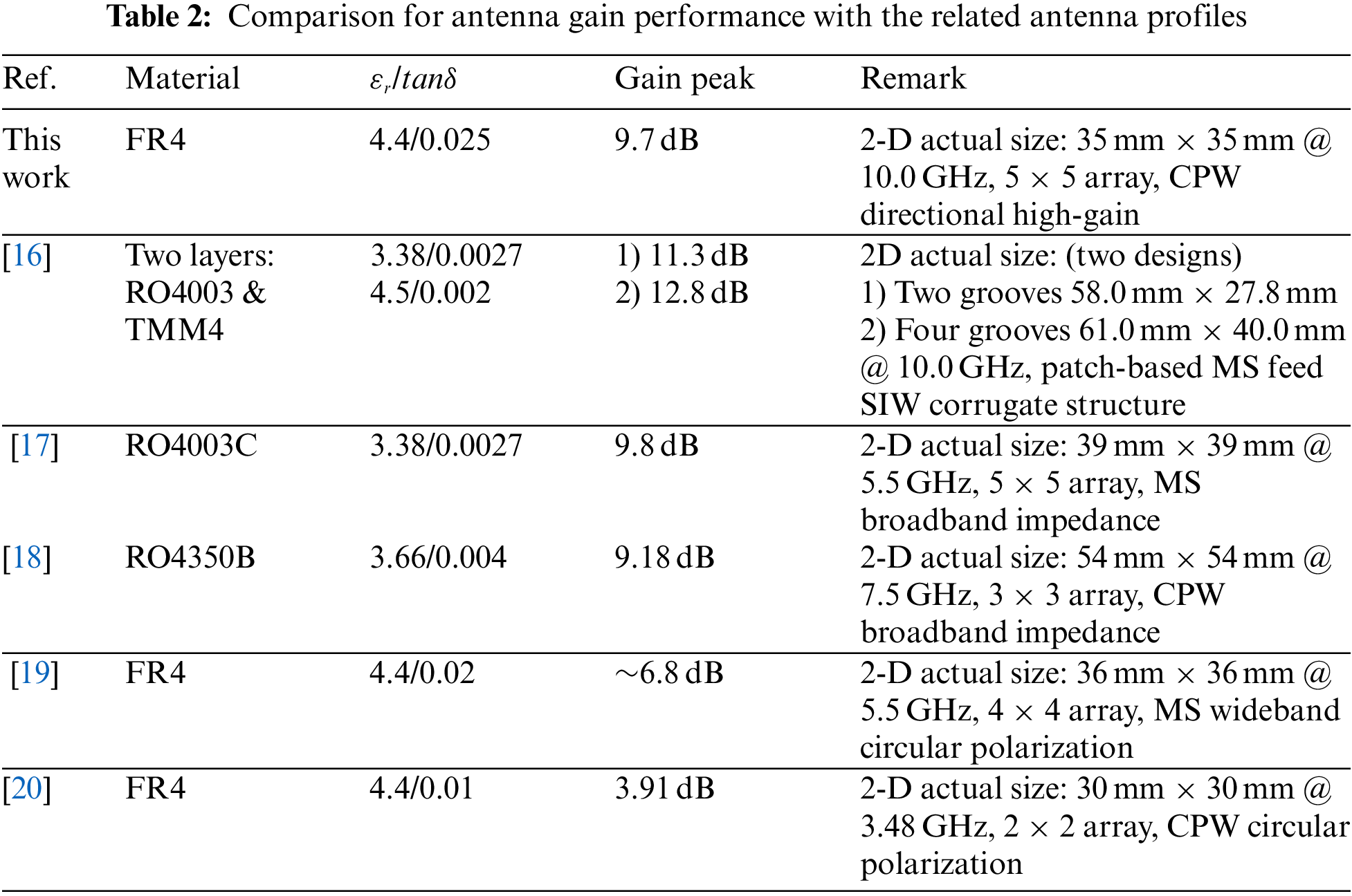
The comparison for antenna gains with the similar planar antenna profiles is tabulated in Tab. 2. In their referred works, the recent proposed antenna structures are corresponding to the periodic surfaces and the primary aperture sources with the specified design patterns. The size of the periodic elements, target frequencies, transmission feeders (CPW and microstrip (MS)) and contributions in design and implementation are remarked. The types of the dielectrics with their properties of the relative permittivity (
The characterization and verification of the AMC-metamaterial planar antenna has been successful reported in obtaining the high gain radiation with a low-profile structure and design. In this work, the magnetic response in the AMC metamaterial enables the high directional antenna. The characteristic of the AMC response is associated with the EM field in a thin cavity which is dominated by the parallel-surface structure. The antenna mechanism comes up with the field interaction of the AMC metamaterial and the primary excitation as a source feeder. The material properties in the AMC have been examined to indicate the electric primitivity and magnetic permeability which reveals the strong magnetic response at the resonant frequency. The loss effect in the dielectric gives the influence of the field absorption. The AMC structures can be a guided media to enhance a field radiation with the embedded narrow aperture as a magnetic dipole. As reported, the magnetic characteristic in the AMC structure is the key effect to collimate and guide the field at the frequency response. The compact dimension of the entire antenna structure is 35.0 × 35.0 × 0.8 mm3 (1.17λ × 1.17λ × 0.027λ) operating at 10 GHz for 5G evolution.
Funding Statement: This research was funded by National Science, Research and Innovation Fund (NSRF), and King Mongkut’s University of Technology North Bangkok with Contract No. KMUTNB-FF-65-26.
Conflicts of Interest: The authors declare that they have no conflicts of interest to report regarding the present study.
References
1. D. Sievenpiper, L. Zhang, R. F. J. Broas, N. G. Alexopolous and E. Yablonovitch, “High-impedance electromagnetic surfaces with a forbidden frequency band,” IEEE Transactions on Microwave Theory & Techniques, vol. 47, no. 11, pp. 2059–2074, 1999. [Google Scholar]
2. B. A. Munk, “Element types: A comparison,” in Frequency Selective Surfaces: Theory and Design, 1st ed., New York, USA: Wiley-Interscience Publication, pp. 26–62, 2000. [Google Scholar]
3. S. Ahmad, K. N. Paracha, Y. A. Sheikh, A. Ghaffar, A. D. Butt et al., “A metasurface-based single-layered compact AMC-backed dual-band antenna for off-body IoT devices,” IEEE Access, vol. 9, pp. 159598–159615, 2021. [Google Scholar]
4. A. Alemaryeen and S. Noghanian, “On-body low-profile textile antenna with artificial magnetic conductor,” IEEE Transactions on Antennas & Propagation, vol. 67, no. 6, pp. 3649–3656, 2019. [Google Scholar]
5. M. Amiri, F. Tofigh, N. Shariati, J. Lipman and M. Abolhasan, “Review on metamaterial perfect absorbers and their applications to IoT,” IEEE Internet of Things Journal, vol. 8, no. 6, pp. 4105–4131, 2021. [Google Scholar]
6. Y. Zhang, J. von Hagen, M. Younis, C. Fischer and W. Wiesbeck, “Planar artificial magnetic conductors and patch antennas,” IEEE Transactions on Antennas & Propagation, vol. 51, no. 10, pp. 2704–2712, 2003. [Google Scholar]
7. H. Askari, N. Hussain, D. Choi, M. A. Sufian, A. Abbas et al., “An AMC-based circularly polarized antenna for 5G sub-6 GHz communications,” Computers, Materials & Continua, vol. 69, no. 3, pp. 2997–3013, 2021. [Google Scholar]
8. I. Aitbar, N. Shoaib, A. Alomainy, A. Quddious, S. Nikolaou et al., “AMC integrated multilayer wearable antenna for multiband wban applications,” Computers, Materials & Continua, vol. 71, no. 2, pp. 3227–3241, 2022. [Google Scholar]
9. A. Feresidis, G. Goussetis, S. Wang and J. Vardaxoglou, “Artificial magnetic conductor surfaces and their application to low profile highgain planar antennas,” IEEE Transactions on Antennas & Propagation, vol. 53, no. 1, pp. 209–215, 2005. [Google Scholar]
10. A. Ourir, A. de Lustrac and J. -M. Lourtioz, “All-metamaterial-based subwavelength cavities (lambda/60) for ultrathin directive antennas,” Applied Physics Letters, vol. 88, no. 8, pp. 084103/1–084103/3, 2006. [Google Scholar]
11. C. Mateo-Segura, G. Goussetis and A. P. Feresidis, “Sub-wavelength profile 2-D leaky-wave antennas with two periodic layers,” IEEE Transactions on Antennas & Propagation, vol. 59, no. 2, pp. 416–424, 2011. [Google Scholar]
12. Y. Sun, Z. N. Chen, Y. Zhang, H. Chen and T. S. P. See, “Subwavelength substrate-integrated fabry-pérot cavity antennas using artificial magnetic conductor,” IEEE Transactions on Antennas & Propagation, vol. 60, no. 1, pp. 30–35, 2012. [Google Scholar]
13. S. Kumar, A. S. Dixit, R. R. Malekar, H. D. Raut and L. K. Shevada, “Fifth generation antennas: A comprehensive review of design and performance enhancement techniques,” IEEE Access, vol. 8, pp. 163568–163593, 2020. [Google Scholar]
14. M. Ashfaq, S. Bashir, S. I. Hussain Shah, N. A. Abbasi, H. Rmili et al., “5G antenna gain enhancement using a novel metasurface,” Computers, Materials & Continua, vol. 72, no. 2, pp. 3601–3611, 2022. [Google Scholar]
15. W. -H. Hui, Y. Guo and X. -P. Zhao, “A simple linear-type negative permittivity metamaterials substrate microstrip patch antenna,” Materials, vol. 14, no. 16, pp. 4398, 2021. [Google Scholar]
16. M. M. Honari, R. Mirzavand, J. Melzer and P. Mousavi, “A new aperture antenna using substrate integrated waveguide corrugated structures for 5G applications,” IEEE Antennas and Wireless Propagation Letters, vol. 16, pp. 254–257, 2017. [Google Scholar]
17. W. Liu, Z. N. Chen and X. Qing, “Metamaterial-based low-profile broadband aperture-coupled grid-slotted patch antenna,” IEEE Transactions on Antennas & Propagation, vol. 63, no. 7, pp. 3325–3329, 2015. [Google Scholar]
18. J. Wang, H. Wong, Z. Ji and Y. Wu, “Broadband CPW-fed aperture coupled metasurface antenna,” IEEE Antennas and Wireless Propagation Letters, vol. 18, pp. 517–520, 2019. [Google Scholar]
19. J. Dong, C. Ding and J. Mo, “A low-profile wideband linear-to-circular polarization conversion slot antenna using metasurface,” Materials, vol. 13, no. 5, pp. 1164, 2020. [Google Scholar]
20. A. Verma, A. K. Singh, N. Srivastava, S. Patil and B. Kanaujia, “Slot loaded EBG-based metasurface for performance improvement of circularly polarized antenna for WiMAX applications,” International Journal of Microwave and Wireless Technologies, vol. 12, no. 3, pp. 212–220. 2020. [Google Scholar]
21. S. Suyama, T. Okuyama, Y. Kishiyama, S. Nagata and T. Asai, “A study on extreme wideband 6G radio access technologies for achieving 100 Gbps data rate in higher frequency bands,” IEICE Transactions on Communications, vol. E104.B, no. 9, pp. 992–999, 2021. [Google Scholar]
22. G. Kim and S. Kim, “Design and analysis of dual polarized broadband microstrip patch antenna for 5G mmWave antenna module on FR4 substrate,” in IEEE Access, vol. 9, pp. 64306–64316, 2021. [Google Scholar]
23. S. Pan, C. Guclu and F. Capolino, “Effect of losses on the performance of very thin artificial magnetic conductors,” in Proc. URSI Int. Symp. Electromagn Theory (EMTS), Hiroshima, Japan, pp. 404–407, 2013. [Google Scholar]
24. J. A. Porto, F. J. García-Vidal and J. B. Pendry, “Transmission resonances on metallic gratings with very narrow slits,” Physical Review Letters, vol. 83, pp. 2845–2848, 1999. [Google Scholar]
25. G. Lu, X. Li, Y. Zhao, K. Zhang, F. Yan et al., “Near-perfect transmission of a low-profile resonant structure with artificial magnetic conductor metamaterials,” AIP Advances, vol. 11, no. 8, pp. 085106-1–085106-6, 2021. [Google Scholar]
26. X. Chen, T. M. Grzegorczyk, B. I. Wu, J. Pacheco and J. A. Kong, “Robust method to retrieve the constitutive effective parameters of metamaterials,” Physical Review E, vol. 70, no. 1, pp. 016608-1–016608-7, 2004. [Google Scholar]
27. D. R. Smith, D. C. Vier, Th. Koschny and C. M. Soukoulis, “Electromagnetic parameter retrieval from inhomogeneous metamaterials,” Physical Review E, vol. 71, pp. 036617-1–036617-1, 2005. [Google Scholar]
28. C. A. Balanis, “Babinet’s Principle,” in Antenna Theory: Analysis and Design, 3rd ed., Hoboken, NewYork, USA: John Wiley & Sons, Inc., pp. 616–620, 2005. [Google Scholar]
29. C. T. Tai and S. A. Long, “Dipoles and monopoles,” In: J. L. Volakis (Ed.) Antenna Engineering Handbook, 4th ed., New York: McGraw Hill, pp. 4-1–4-32, 2007. [Google Scholar]
30. R. N. Simons, “Coplanar Waveguide Short Circuit,” in Coplanar Waveguide Circuits, Components and Systems, 1st ed., New York, USA: Wiley-Interscience, pp. 241–243, 2001. [Google Scholar]
31. G. Mayhew-Ridgers, P. A. Jaarsveld, J. W. Odendaal and J. Joubert, “Accurate gain measurements for large antennas using modified gain-transfer method,” IEEE Antennas and Wireless Propagation Letters, vol. 13, pp. 369–371, 2014. [Google Scholar]
Cite This Article
 Copyright © 2023 The Author(s). Published by Tech Science Press.
This work is licensed under a Creative Commons Attribution 4.0 International License , which permits unrestricted use, distribution, and reproduction in any medium, provided the original work is properly cited.
 Downloads
 Citation Tools