
 Submit a Paper
 Propose a Special lssue
 Open Access
ARTICLE
Triple-Band Circularly Polarized Dielectric Resonator Antenna (DRA) for Wireless Applications
1 Advanced Communication Engineering (ACE) Centre of Excellence, Faculty Technology of Electrical Engineering, Universiti Malaysia Perlis, Pauh, Perlis, 02600, Malaysia
2 Advanced Communication Engineering (ACE) Centre of Excellence, Faculty Technology of Electronic Engineering, Universiti Malaysia Perlis, Pauh, Perlis, 02600, Malaysia
3 Department of Electrical Engineering, Universitas Sumatera Utara, Medan, 20155, Indonesia
4 Wireless Communication Center, Universiti Teknologi Malaysia, Skudai, 81310, Johor, Malaysia
5 Korhan Cengiz College of Information Technology, University of Fujairah, Fujairah, 00000, United Arab Emirates
6 Malaysia-Japan International Institute of Technology (M-JIIT), Universiti Teknologi Malaysia, Kuala Lumpur, 54100, Malaysia
* Corresponding Author: Mohd Najib Mohd Yasin. Email:
Computers, Materials & Continua 2023, 74(1), 313-325. https://doi.org/10.32604/cmc.2023.031706
Received 25 April 2022; Accepted 15 June 2022; Issue published 22 September 2022
 View Full Text
 Download PDF
Abstract
This paper proposes a new dielectric resonator antenna (DRA) design that can generate circularly polarized (CP) triple-band signals. A triple-band CP DRA antenna fed by a probe feed system is achieved with metal strips structure on side of DRA structure. The design start with conventional rectangular DRA with F shaped metal strips on DRA structure alongside the feed. Then, the F metal strip is enhanced by extending the length of the metal strip to obtain wider impedance bandwidth. Further improvement on the antenna performance is observed by improvised the conventional DRA structure. The method of removing part of DRA bottom resulted to higher antenna gain with triple band CP. The primary features of the proposed DRA include wide impedance matching bandwidth (BW) and broadband circular polarization (CP). The primary features of the proposed DRA include wide impedance matching bandwidth (BW) and broadband circular polarization (CP). The CP BW values recorded by the proposed antenna were ∼ 11.27% (3.3–3.65 GHz), 12.18% (4.17–4.69 GHz), and 1.74% (6.44–6.55 GHz) for impedance-matching BW values of 35.4% (3.3–4.69 GHz), 1.74% (5.36–5.44 GHz), and 1.85% (6.41–6.55 GHz) with peak gains of 6.8 dBic, 7.6 dBic, and 8.5 dBic, respectively, in the lower, central, and upper bands. The prototype of the proposed antenna geometry was fabricated and measured. A good agreement was noted between the simulated and the measured results.Keywords
Since the past few years, dielectric resonator antenna (DRA) has garnered much attention across the globe. The rapid progress of modern communication systems from microwave-to-millimeter wave has promoted the use of DRA as a radiator, primarily for its function as a better solution to avoid undesired radiation loss, conduction loss, and low efficiency noted in conventional microstrip or waveguide antennas at high frequencies [1]. Some notable attractive physical characteristics of the DRA include 3D-design flexibility, light in weight, low in cost, ease of excitation, as well as several enhanced performances in terms of bandwidth (BW), gain, and circular polarization (CP) [2]. These DRAs with CP have received plenty of attention as they can yield higher signal quality, lower fading and multipath, as well as resistant toward polarization mismatch; thus making these DRAs more appropriate for wireless communication systems than linearly polarized (LP) antennas [3–8].
Although many methods have been proposed to generate CP in DRAs (e.g., dual and single excitation techniques), they all seemed to result in complex feeding network and larger antenna area [9–11]. Single, dual, and quadrature feeds are the most common techniques deployed to produce CP from DRAs [12,13]. Wider impedance matching (S11) and axial ratio (AR) (3-dB) bandwidths are typically achieved via quadrature or dual-feed mechanism, which requires the inclusion of a power divider or an external hybrid coupler–signifying increment in total size, intricacy, and loss of the antenna system. On the other hand, the single-feed technique, which generates CP through the engineering of dielectric resonator geometry and the use of a specific feeding structure, has a simple feeding network but suffers from narrow return loss/AR bandwidth of less than 10%. As a result, more effort has been made to enhance the bandwidth of CP singly-fed DRA [14]. Alternatively, researchers in [15,16] proposed a mechanical technique that involves filling the DRA with fluids. The aim of simple feeding method is achieved, but the main concern is to generate a broad AR bandwidth.
Apart from feeding techniques, previous strategies to generate CP include layering the DR structure [5], drilling and cutting the DRs to modify the basic DR forms [3–4,11], multi-dielectric layering [17], and inclusion of a diode to the reconfigurable band [18]. The most recent method [19] is to place metamaterial on top of or at the center of the DRA.
In [2], CP was generated by using the strip-fed excitation approach with a rectangular DRA and a parasitic patch added to the corner of the DRA structure. The antenna had a 14% impedance bandwidth centered at 3.4 GHz and a 3-dB AR bandwidth of 2.7%. In [3,9], a triple-band dual-sense CP hybrid DRA was designed by using a modified hexagonal DR and top-loaded by a square microstrip ring (SMR), which resulted in a triband CP DRA that resonated at 1.9, 2.73, and 3.7 GHz [3]. Meanwhile, the authors of [9] presented a top-loaded modified Alford loop CP DRA with CP frequencies of 1.937, 2.45, and 3.51 GHz. In [17], a single-feed high-order triple-band CP was produced by using a 2-layer DRA with different permittivity, whereas in [20], CP was generated by using double stub strip on the DRA. The methods mentioned above did produce triple CP, but the AR bandwidth was small. The production of single-and dual-band CP antennas is simple and easy when compared to triple-band CP [5,10,21,22].
Turning to this present study, the proposed antenna produced triple-band CP fed by a coaxial cable to a double stub metal strip. Without any addition of external material or complicated DRA design, a triple-band CP with good AR bandwidth CP was achieved with this proposed technique. The parasitic and external stub effects present a novel method for generating a large impedance bandwidth that functions in a higher mode [8,23,24]. The proposed method that cuts part of the DRA structure was excited to achieve triple-band CP and to enhance the antenna gain. The return losses, AR, radiation patterns, and gain were simulated and measured. The simulated results were in close agreement with those obtained from the measurement. Therefore, this study outlines the details of the proposed DRA design by presenting the parametric design of the antenna, the selection of the proposed antenna design, the reflection coefficient (S11), the BW enhancement, the CP generation, as well as a discussion revolving around the simulation and measurement findings.
A parametric study was executed to investigate the effects of the related metal strip design on impedance and AR BW. Upon considering the proposed design, 3D simulation designs were generated using CST software for DRA at target frequencies ranging from 2 to 7 GHz band. A single element for the design was developed to assess its performance in terms of S11 and AR.
2.1 Parametric Design Study of Metal Strip
This parametric study illustrates a comprehensive picture of the antenna characteristics, apart from determining the impact of the metal strip geometry parameters on the antenna performance. Two geometric parameters; (i) length and height of metal strip and (ii) DRA design, were analyzed in this study.
Referring to Fig. 1, the metal strips were added to DRAs I to V. The designs incorporated a rectangular DRA made from alumina (ECCOSTOCK) with permittivity at ɛr = 10, metal strip for excitation purpose, parasitic patch, and ground plane made of PEC material. The DRA (size: H = 26.1 mm, L = 21.3 mm, and W = 14.3 mm) was placed in the middle of the ground plane and was excited by using the probe feed technique. A parasitic patch was embedded to improve both return loss and CP waves BW.
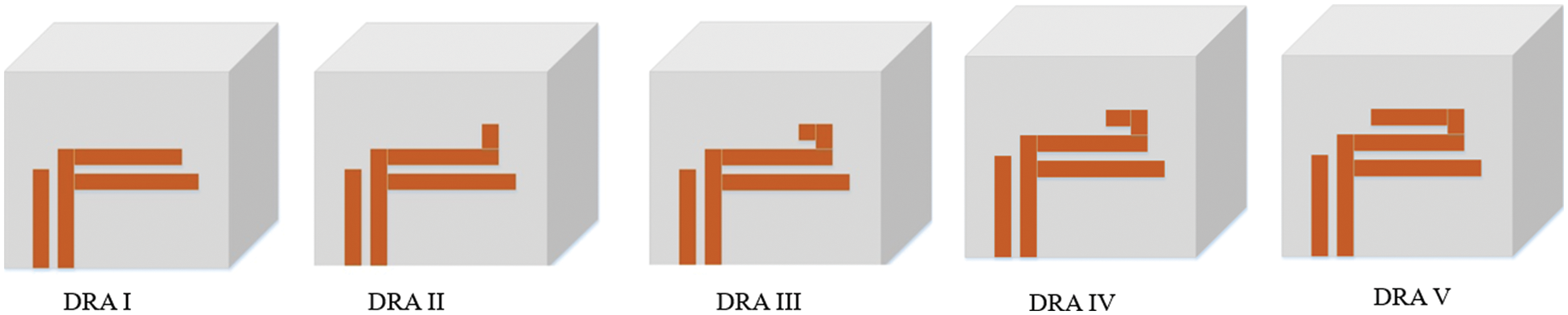
Figure 1: The different designs of metal strip embedded to the optimized design
In order to improve the impedance BW of DRA I, DRA II was designed with a short metal strip (1 mm × 2 mm) added on top of the second metal strip observed in DRA I. However, the outcome was nearly identical as shown in the simulated return loss (see Fig. 2). Next, to enhance the impedance BW, another square (3 mm × 2 mm) metal strip was added to develop DRA III. Further extending the metal strip from DRA III to DRA IV and DRA V have resulted in reducing the impedance bandwidth and also decreasing the S11 value to less than −10 dB. Therefore, the optimized design of parasitic patch is obtained. The extended metal strip improved the −10 dB BW with impedance BW ∼ 44.76% at lower frequency. The simulated return loss of the proposed DRAs is reflected in Fig. 2, with the antenna resonating at 3.25–4.76 GHz and 5.98–6.09 GHz.
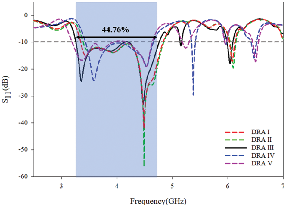
Figure 2: Reflection coefficient (S11) of the DRAs
The result of S11 vs. AR plotted in Fig. 3 shows that the CP occurred at two different frequencies. When compared to DRAs I and II, DRA III produced optimized outcome with broader BW and matching reflection coefficient with AR at lower frequencies. Hence, DRA III with optimized metal strip was selected for further enhancement and is discussed in the following section.
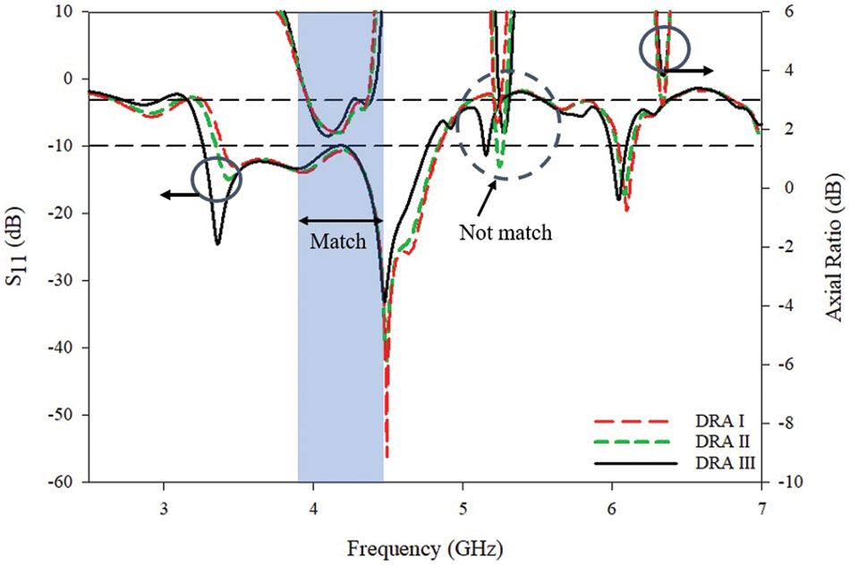
Figure 3: Reflection coefficient (S11) and axial ratio (AR) of the DRAs
2.2 Optimized Antenna Configuration
The proposed design of the metal strip (see Fig. 1 for DRA III) was further enhanced. The dimensions of the patch antenna and the metal strip are illustrated in Fig. 4. The DRA material and size are as mentioned previously.
Next, DRA III was further optimized by cutting the DRA at the bottom at the base plate. Fig. 5 presents the detailed geometry of the DRA.
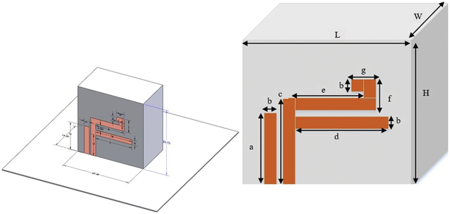
Figure 4: Front view of DRA III with geometry a = 11 mm, b = 2 mm, c = 13 mm, d = 14 mm, e = 11 mm, f = 5 mm, and g = 3 mm
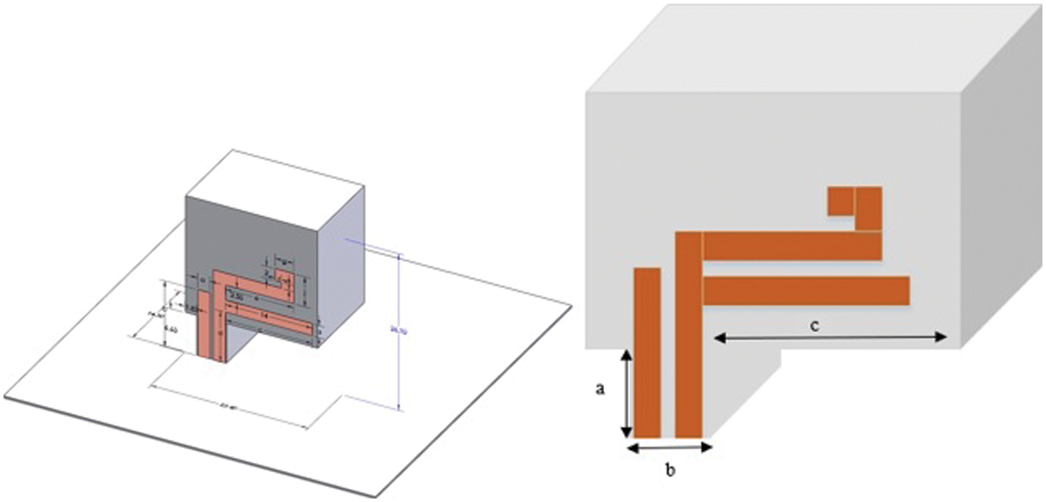
Figure 5: Front view of cut-off DRA (proposed DRA) with a = 4.68 mm, b = 1.83 mm, and c = 6.63 mm
Circularly polarized (CP) DRAs can be established with a probe feed mechanism and patch antenna, which presents an asymmetry in the DRA structure. Fig. 6 shows the DRA design transition from DRA I to the proposed DRA.
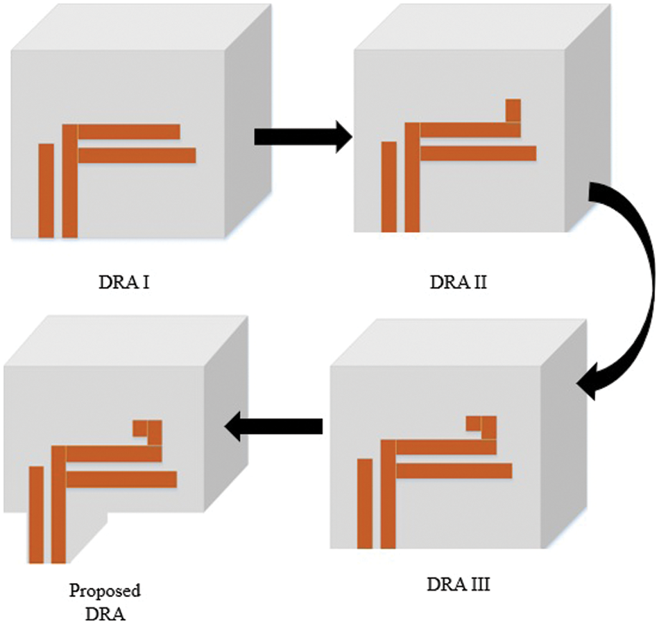
Figure 6: Transition from DRA I to a single element in the proposed DRA
2.3 Simulated Results of Single DRA for Design III and Proposed DRA
The simulated effects of DRA III and proposed DRA are discussed in this subsection. As illustrated in Fig. 7, DRA III generated fractional return loss |S11 | ≤ −10 dB of ∼ 44.76% (3.26–4.76 GHz) with −24.371 dB having a center frequency at 3.35 GHz, 0.77% (5.13–5.17 GHz) having a center frequency at 5.14 GHz with −11.33 dB, and 1.97% (5.97–6.09 GHz) centered at the frequency of 6.04 GHz with −18.03 dB. As for the proposed DRA, the fractional return loss |S11 | ≤ −10 dB of ∼ 35.4% (3.43–4.69 GHz) displayed a center frequency at 3.56 GHz with −20.21 dB, 1.74% (5.34–5.44 GHz) having a center frequency at 5.41 GHz with −17.03 dB, and 1.85% (6.41–6.55 GHz) having a center frequency at 6.47 GHz with −19.25 dB.
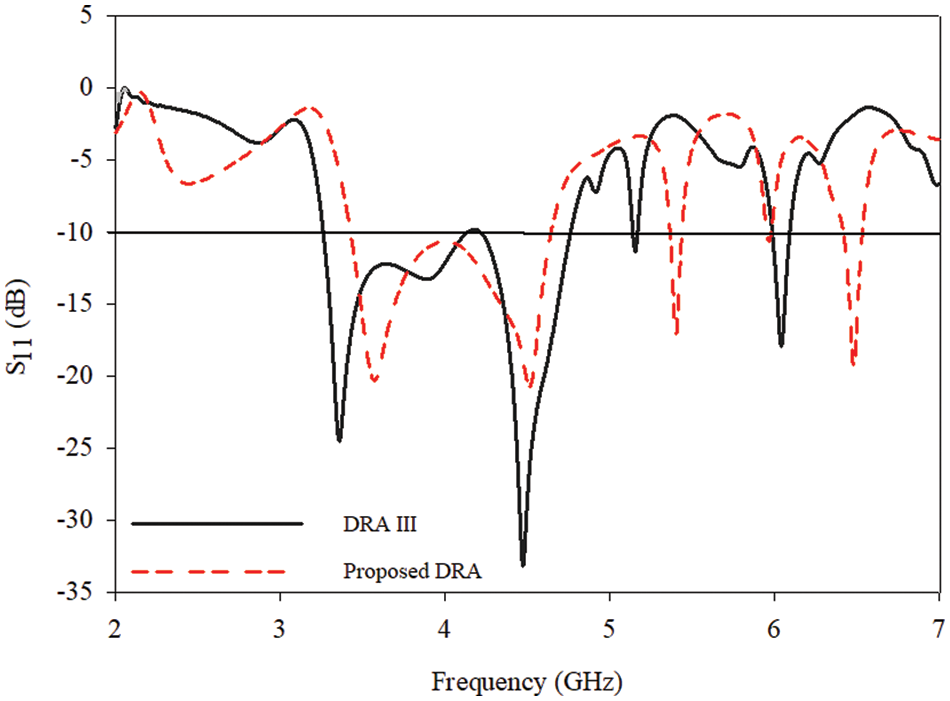
Figure 7: Comparison of return loss (S11) for DRA III and proposed DRA
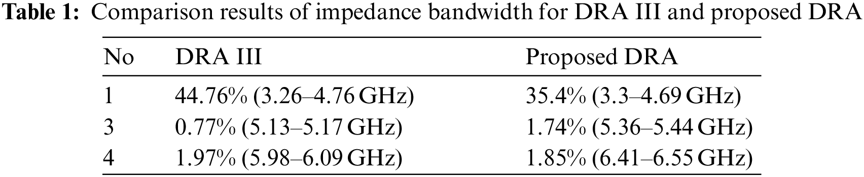
Each antenna produced three CP, with both DRAs producing good results. However, DRA III yielded a higher percentage of impedance bandwidth than the proposed DRA. Despite the large impedance bandwidth, the overlapping bandwidth between return loss and AR emerged as a crucial feature to check for, as both frequencies must match for optimal performance. Tab. 1 lists the comparison results.
The simulated outcomes of 3-dB AR BW for DRA III and proposed DRA are presented in Fig. 8. Notably, DRA III recorded two 3-dB AR BWs at ∼ 10.27% (3.95–4.38 GHz) and 0.53% (5.28–5.31 GHz). Meanwhile, the proposed design generated three 3-dB AR BWs at ∼ 11.27% (3.3–3.68 GHz), 12.18% (4.19–4.69 GHz), and 1.74% (6.44–6.55 GHz).
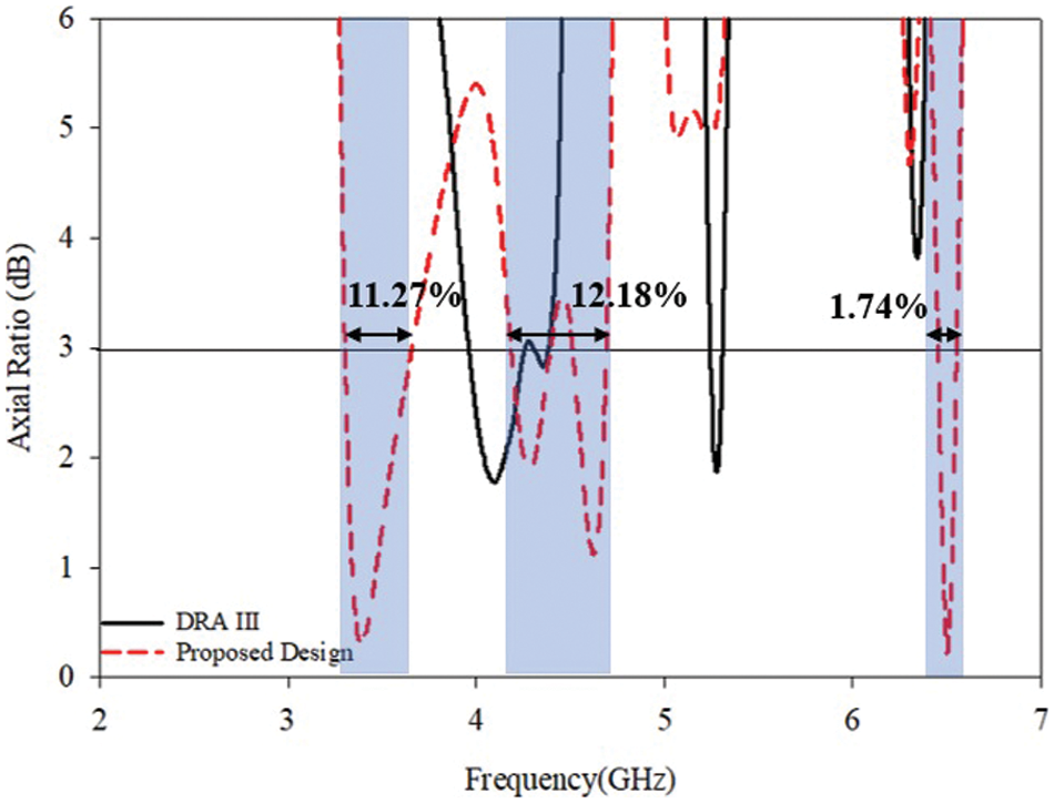
Figure 8: Comparison of axial ratio (AR) one antenna for DRA III and proposed DRA
The differences noted in 3-dB AR BWs of both designs are summarized in Tab. 2. The proposed DRA exhibited better performance than DRA III due to the wider with three 3-dB AR BW outcomes, whereby another CP was generated at a higher frequency centered at 6.49 GHz (see Fig. 8).
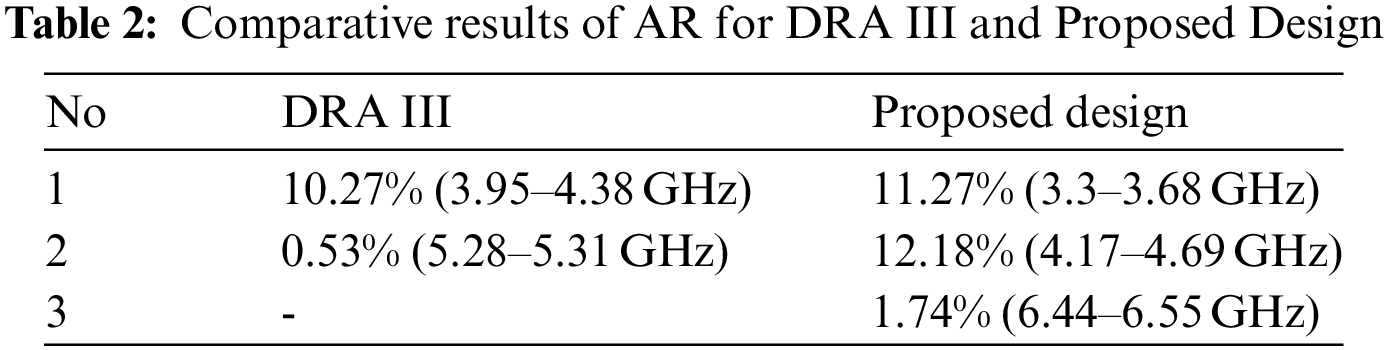
Fig. 9 presents the overlapping impedance BW with 3-dB AR BW. Apparently, the proposed DRA demonstrated superior performance over DRA III, mainly because the overlapping impedance matched at three different frequencies. Additionally, the proposed DRA displayed high gain at 6.8 dBic, 7.6 dBic, and 8.5 dBic at the respective resonant frequencies. The gain values for both DRA III and proposed DRA are plotted in Fig. 10.
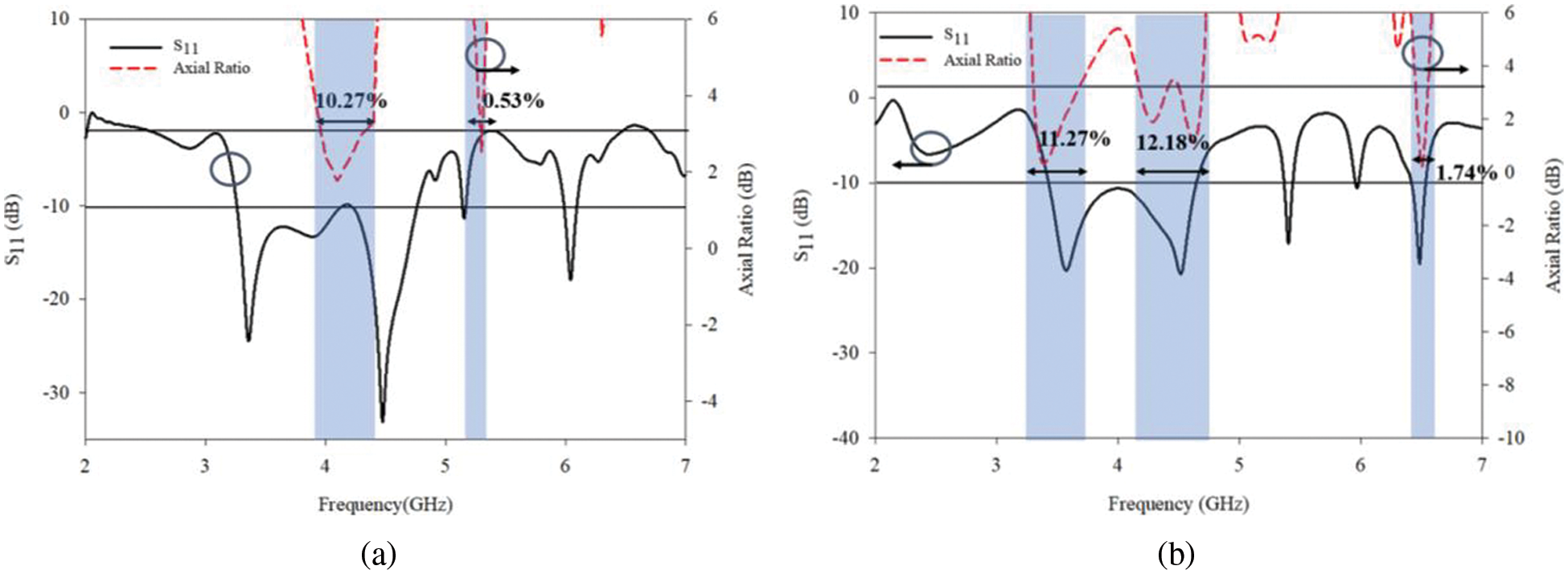
Figure 9: S11 and 3-dB axial ratio (AR) characteristics for a) DRA III and b) proposed DRA
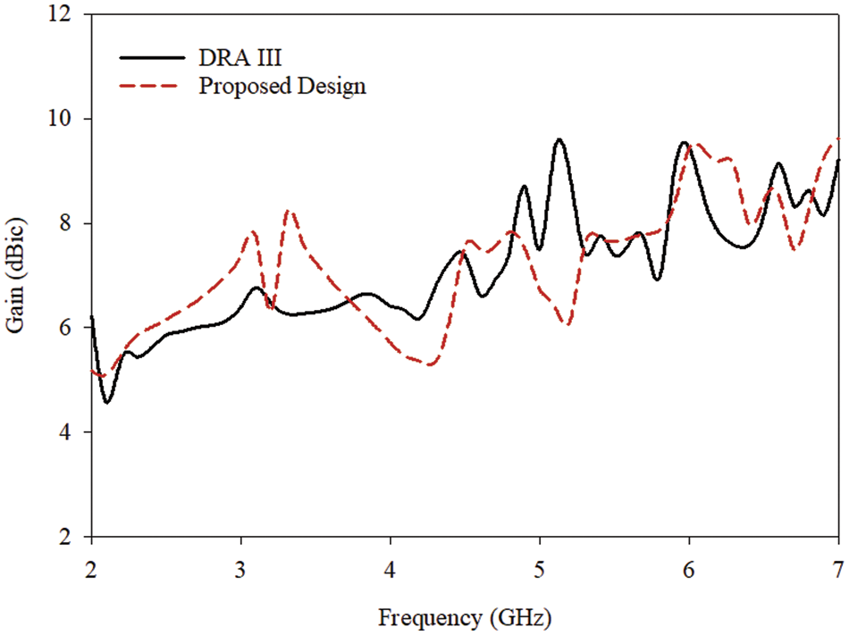
Figure 10: Gain values for DRA III and proposed design
Figs. 11 and 12 illustrate E-field and H-field for the proposed design with the degenerate mode pair of the fundamental modes of TEx 21, TEx 21 and TEx 42 at 3.57 GHz, 4.52 GHz, and 6.48 GHz.
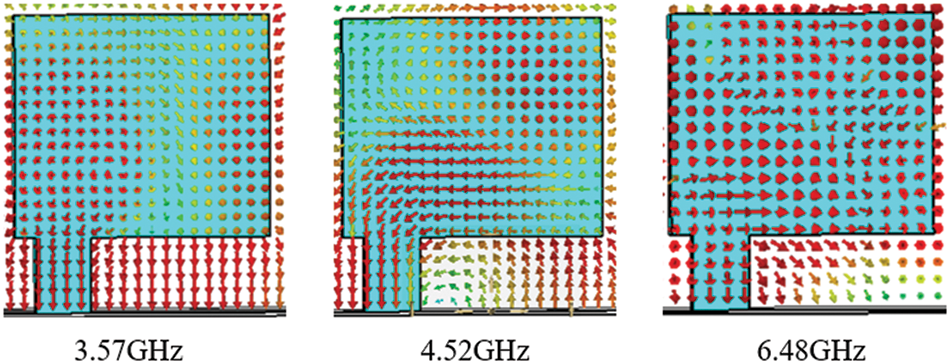
Figure 11: E-Field proposed design
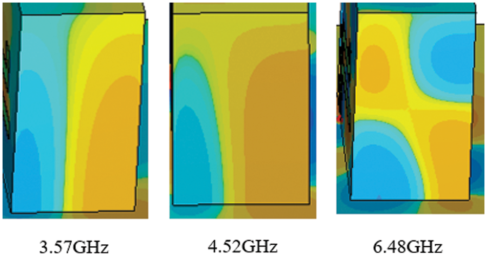
Figure 12: H-Field in the proposed design
The computed vector surface current distribution is presented to further examine the CP. Fig. 13 showcases the simulated surface current distribution on the metal feed and the parasitic patch for the anticipated antenna at a frequency of 3.57 GHz with varied phase angles of phi = 0o, 90o, 180o, and 270o. The figure displays that the vector surface current distribution was executed via rotation with various phase angles and rotations occurring in anti-clockwise orientation; reflecting the presence of left-handed CP (LHCP).
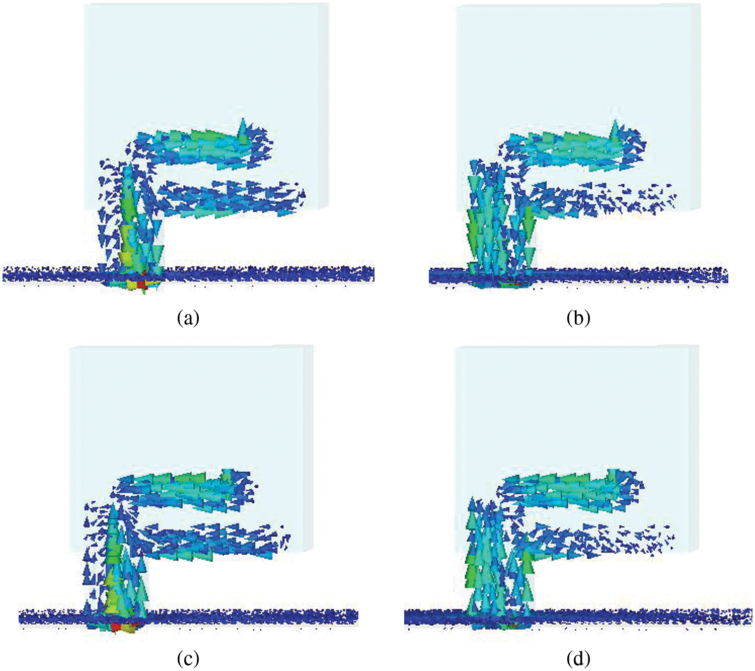
Figure 13: Surface current distribution at 3.57 GHz with a) phi = 0o, b) phi = 90o, c) phi = 180o, and d) phi = 270o
3 Comparison Between Simulated and Measured Results
The prototype of the proposed design was fabricated and measured to verify the simulation outcomes. Fig. 14 presents the prototype of the proposed DRA (zoomed view) and the measurement setup to measure both reflection coefficients and radiation pattern in an anechoic chamber.
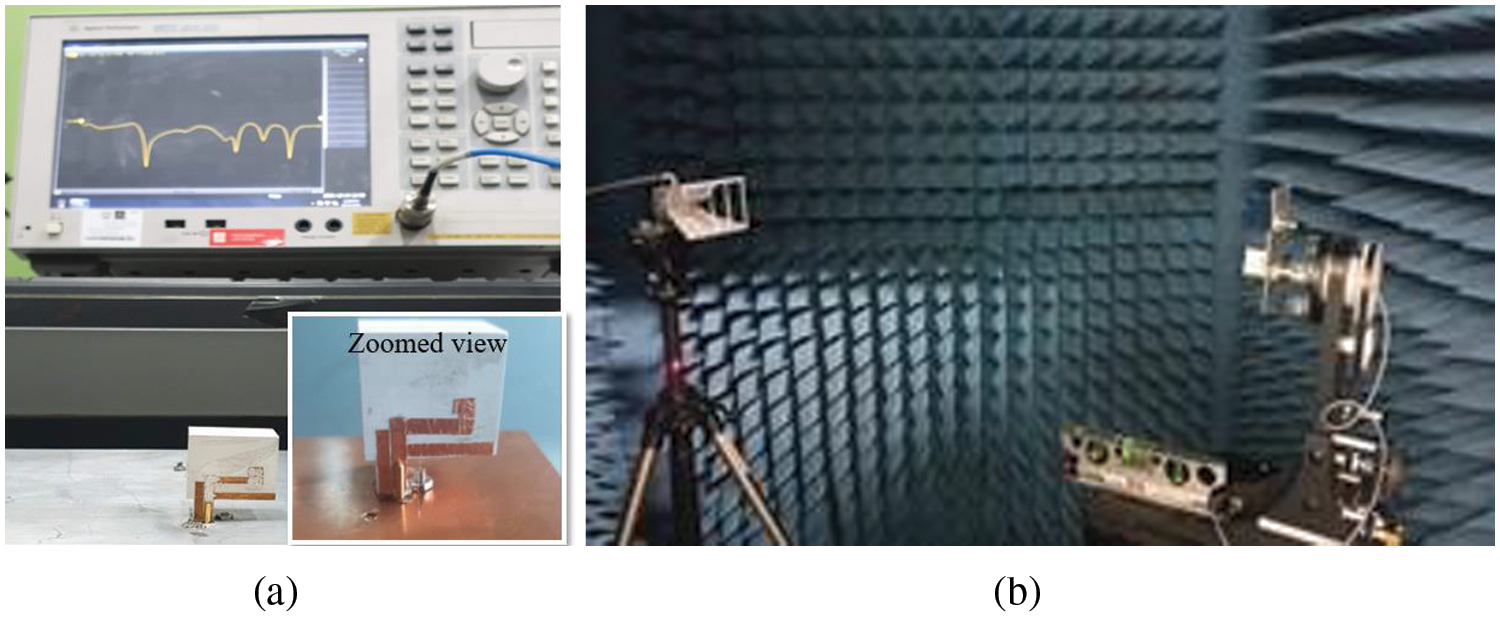
Figure 14: The measurement of the proposed DRA a) reflection coefficient using VNA and b) axial ratio (AR) and radiation pattern in anechoic chamber
Fig. 15 illustrates the results of both simulated and measured reflection coefficients and AR. Notably, a mismatch was observed due to inaccuracies during antenna construction. This is ascribed to the air gap noted between the DRA and the ground plane in the constructed antenna against the simulated antenna. Besides, both AR and S11 fell within the same frequency ranges for simulated and measured designs, which enhanced the performance of the antenna.
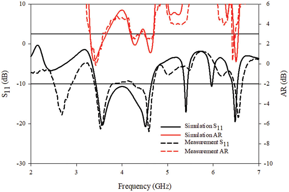
Figure 15: The axial ratio (AR) of simulated and measured proposed DRA (AR vs. frequency)
The simulated and measured radiation patterns of the proposed DRA were compared (see Fig. 16). The results were taken at 3.6, 4.9, and 5.4 GHz. Apparently, the antenna reflected an LHCP as the difference between LHCP and RHCP patterns is at least 15 dB.
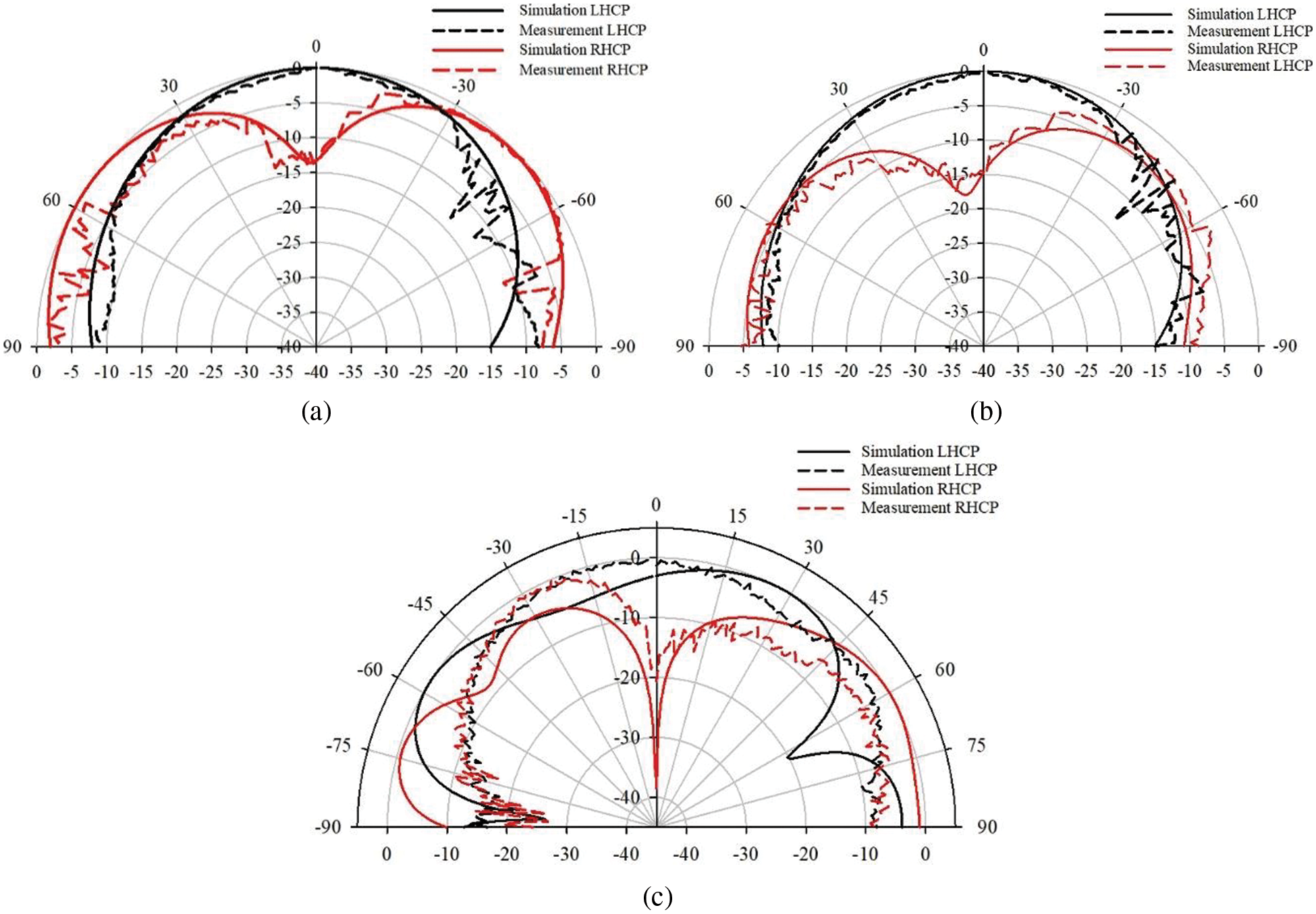
Figure 16: Radiation pattern at a) 3.6 GHz, b) 4.5 GHz, and c) 6.5 GHz
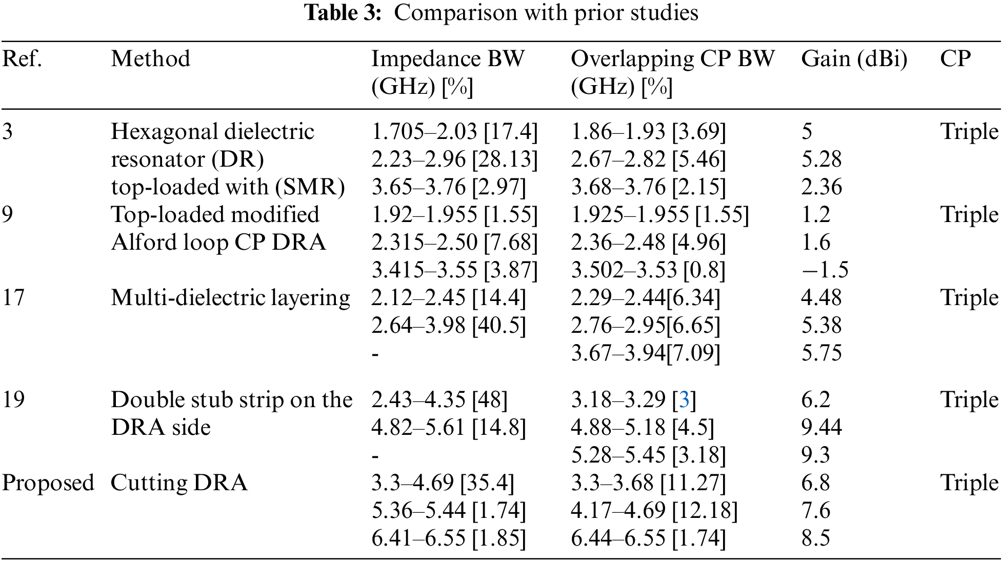
In comparison with past studies (see Tab. 3), the proposed DRA predominantly yielded triple-band CP with the most significant match or overlapping CP BW of ∼ 11% at lower frequency. In addition, considerable improvement was observed in terms of gain, when compared to other prior reported results.
In conclusion, a modified novel and compact CP DRA structure was designed, developed, and experimentally validated in this study. The removal of a section at the bottom of the DRA and the addition of metal strips at one side of the DRA generated triple-band CP, along with significant impedance and AR BW. Each related parameter was thoroughly examined and optimized to obtain optimum performance. In comparison to the conventional design, the DRA proposed in this present study yielded triple-band CP with simple construction. The proposed antenna recorded AR BW values of 11.27% (3.3–3.65 GHz), 12.18% (4.17–4.69 GHz), and 1.74% (6.44–6.55 GHz) that matched the impedance-matching BW values of 35.4% (3.3–4.69 GHz), 1.74% (5.36–5.44 GHz), and 1.85% (6.41–6.55 GHz).
Acknowledgement: The authors would like to acknowledge the support recerived from the International Grant (9008–00021) between Universiti Malaysia Perlis (UniMAP) and Universitas Muhammadiyah Sumatera Utara (UMSU), Indonesia.
Funding Statement: This research work was funded by Universiti Malaysia Perlis (UniMAP).
Conflicts of Interest: The authors declare that they have no conflicts of interest to report regarding the present study.
References
1. U. Banerjee, A. Karmakar and A. Saha, “A review on circularly polarized antennas, trends and advances,” International Journal of Microwave and Wireless Technologies, vol. 12, no. 9, pp. 922–943, 2020. [Google Scholar]
2. S. K. K. Dash and T. Khan, “Recent developments in bandwidth improvement of dielectric resonator antennas,” International Journal of RF and Microwave Computer Aided Engineering, vol. 29, no. 6, pp. 139518–139525, 2018. [Google Scholar]
3. A. Altaf and M. Seo, “Triple-band dual-sense circularly polarized hybrid dielectric resonator antenna,” Sensors, vol. 18, pp. 3899, 2018. [Google Scholar]
4. X. Fang, K. W. Leung and E. H. Lim, “Singly-fed dual-band circularly polarized,” IEEE Antennas and Wireless Propagation Letter, vol. 13, pp. 995–998, 2014. [Google Scholar]
5. M. Zou and J. Pan, “Wide dual-band circularly polarized stacked rectangular dielectric resonator antenna,” IEEE Antennas and Wireless Propagation Letter, vol. 15, pp. 1140–1143, 2016. [Google Scholar]
6. U. Illahi, J. Iqbal, M. I. Sulaiman, M. Alam, M. M. Su’ud et al., “Design and development of a singly-fed circularly polarized rectangular dielectric resonator antenna for WiMAX/Satellite/5G NR band applications,” AEU International Journal Electronic Communication, vol. 126, pp. 153443, 2020. [Google Scholar]
7. U. Illahi, J. Iqbal, M. I. Sulaiman, M. Alam, M. M. Su’ud et al., “Singly-fed rectangular dielectric resonator antenna with a wide circular polarization bandwidth and beamwidth for WiMAX/Satellite applications,” IEEE Access, vol. 7, pp. 66206–66214, 2019. [Google Scholar]
8. U. Illahi, J. Iqbal, M. I. Sulaiman, M. Alam, M. M. Su’ud et al., “Design of new circularly polarized wearable dielectric resonator antenna for off-body communication in WBAN applications,” IEEE Access, vol. 7, pp. 150573–150582, 2019. [Google Scholar]
9. C. Cheng, F. Zhang, Y. Yao and F. Zhang, “Triband omnidirectional circularly polarized dielectric resonator antenna with top-loaded alford loop,” International Journal of Antennas and Propagation, vol. 2014, pp. 1–8, 2014. [Google Scholar]
10. Z. Zhao, J. Ren, Y. Liu and Y. Yin, “Wideband dual-feed, dual-sense circularly polarized dielectric resonator antenna,” IEEE Transactions on Antennas and Propagation, vol. 68, pp. 7785–7793, 2020. [Google Scholar]
11. S. Ogurtsov, S. Koziel and A. Bekasiewicz, “Axial ratio improvement of circular polarized dielectric resonator antennas with dual point feeds,” in Proc. of the 2016 IEEE/ACES, Int. Conf. on Wireless Information Technology, Honolulu, HI, USA, vol. 2, pp. 1–2, 2016. [Google Scholar]
12. A. Petosa, in Dielectric Resonator Antenna Handbook, Norwood, MA, USA: Artech House, 2007. [Online]. Available: https://ia801309.us.archive.org/3/items/DielectricResonatorAntennas/Dielectric%20Resonator%20Antennas.pdf. [Google Scholar]
13. K. W. Leung, W. C. Wong, K. M. Luk and E. K. N. Yung, “Circular polarised dielectric resonator antenna excited by dual conformal strips,” Electronic Letter, vol. 36, no. 6, pp. 484–486, 2000. [Google Scholar]
14. X. C. Wang, L. Sun, X. L. Lu, S. Liang and W. Z. Lu, “Single-feed dual band circularly polarized dielectric resonator antenna for CNSS applications,” IEEE Transactions on Antennas and Propagation, vol. 65, no. 8, pp. 4283–4287, 2017. [Google Scholar]
15. M. Wang and Q. X. Chu, “A wideband polarization-reconfigurable water dielectric resonator antenna,” IEEE Antennas Wireless and Propagation Letter, vol. 18, pp. 402–406, 2019. [Google Scholar]
16. Z. Chen and H. Wong, “Liquid dielectric resonator antenna with circular polarization reconfigurability,” IEEE Transactions on Antennas and Propagation, vol. 66, pp. 444–449, 2018. [Google Scholar]
17. A. A. Abdulmajid, Y. Khalil and S. Khamas, “Higher-order-mode circularly polarized two-layer rectangular dielectric resonator antenna,” IEEE Antennas and Wireless Propagation. Letters, vol. 17, pp. 1114–1117, 2018. [Google Scholar]
18. A. Altaf, J. Jung, Y. Yang, K. Y. Lee, K. Hwang et al., “Reconfigurable dual-/triple-band circularly polarized dielectric resonator antenna,” IEEE Antennas Propagation Letter, vol. 19, pp. 443–447, 2020. [Google Scholar]
19. A. K. Dwivedi, A. Sharma, A. K. Singh and V. Singh, “Metamaterial inspired dielectric resonator MIMO antenna for isolation enhancement and linear to circular polarization of waves,” Measurement, vol. 182, pp. 109681, 2021. [Google Scholar]
20. M. F. Zambak, M. N. M. Yasin, I. Adam, J. Iqbal and M. N. Osman, “Higher-order-mode triple band circularly polarized rectangular dielectric resonator antenna,” Applied Sciences, vol. 11, no. 8, pp. 3493, 2021. [Google Scholar]
21. A. Gupta and R. K. Gangwar, “Dual-band circularly polarized aperture coupled rectangular dielectric resonator antenna for wireless applications,” IEEE Access, vol. 6, pp. 11388–11396, 2018. [Google Scholar]
22. Y. Liu, Y. C. Jiao, Z. Weng, C. Zhang and G. Chen, “A novel millimeter-wave dual-band circularly polarized dielectric resonator antenna,” International Journal of RF Microwave and Computer-Aided. Engineering, vol. 29, pp. 930–933, 2019. [Google Scholar]
23. U. Ilahi, M. N. M. Yasin, M. A. Albreeem and M. F. Akbar, “Bandwidth enhancement by using parasitic patch on dielectric resonator antenna for sub-6 GHz 5G NR bands application,” Alexandria Engineering Journal, vol. 61, pp. 5021–5032, 2022. [Google Scholar]
24. J. Iqbal, U. Ilahi, M. F. Ain and Z. A. Ahmad, “A review of wideband circularly polarized dielectric resonator antennas, communication theories and systems,” China Communications, vol. 14, pp. 65–79, 2017. [Google Scholar]
Cite This Article
 Copyright © 2023 The Author(s). Published by Tech Science Press.
This work is licensed under a Creative Commons Attribution 4.0 International License , which permits unrestricted use, distribution, and reproduction in any medium, provided the original work is properly cited.
 Downloads
 Citation Tools