
 Submit a Paper
 Propose a Special lssue
 Open Access
ARTICLE
Intelligent SLAM Algorithm Fusing Low-Cost Sensors at Risk of Building Collapses
Computer Information Technology, Korea National University of Transportation, Chungju, 27469, Korea
* Corresponding Author: Junho Ahn. Email:
Computers, Materials & Continua 2023, 74(1), 1657-1671. https://doi.org/10.32604/cmc.2023.029216
Received 27 February 2022; Accepted 01 April 2022; Issue published 22 September 2022
 View Full Text
 Download PDF
Abstract
When firefighters search inside a building that is at risk of collapse due to abandonment or disasters such as fire, they use old architectural drawings or a simple monitoring method involving a video device attached to a robot. However, using these methods, the disaster situation inside a building at risk of collapse is difficult to detect and identify. Therefore, we investigate the generation of digital maps for a disaster site to accurately analyze internal situations. In this study, a robot combined with a low-cost camera and two-dimensional light detection and ranging (2D-lidar) traverses across a floor to estimate the location of obstacles while drawing an internal map of the building. We propose an algorithm that detects the floor and then determines the possibility of entry, tracks collapses, and detects obstacles by analyzing patterns on the floor. The robot’s location is estimated, and a digital map is created based on Hector simultaneous localization and mapping (SLAM). Subsequently, the positions of obstacles are estimated based on the range values detected by 2D-lidar, and the position of the obstacles are identified on the map using the map update method in semantic SLAM. All equipment are implemented using low-specification devices, and the experiments are conducted using a low-cost robot that affords near-real-time performance. The experiments are conducted in various actual internal environments of buildings. In terms of obstacle detection performance, almost all obstacles are detected, and their positions identified on the map with a high accuracy of 89%.Keywords
Disasters such as fire and collapse occur in buildings annually. According to statistics of the national fire protection agency (NFPA) [1], 1,338,500 cases of fire occurred in buildings and structures in 2020, with 3,500 fatalities and 15,200 injuries recorded. In 2021, a building collapsed in Florida, United States (U.S.) [2], and in 2015, a fire incident occurred at Grenfell tower in the United Kingdom (UK), resulting in 72 fatalities [3]. As disasters are becoming increasingly frequent and more complex, methods for securing effective responses have become increasingly important. In recent years, disaster response robots have been developed to replace human rescuers, as the latter are at risk of being killed when assigned to disaster sites, such as fire sites, to perform search and rescue operations. The Korea institute of robot and convergence has developed a snake-shaped robot [4] that searches narrow spaces and buried areas that cannot be entered easily by humans. The Italian institute of technology (IIT) has developed Centauro [5], a robot that can be used in disaster sites owing to its ability to open valves, open doors, and use tools such as drills. Furthermore, the Massachusetts institute of technology (MIT), U.S., has developed Hermes [6], a robot that is controlled remotely by a human and can operate at the level of humans in disaster situations.
During a disaster, the control tower installed outside the disaster building can use the camera and other sensor attached to the robot deployed inside the disaster building to identify the situation inside the building. To ensure the effective deployment of search and rescue operation personnel, it is important to identify the locations of collapsed floors, objects inside the collapsed building, large debris, etc. However, disaster buildings cannot be entered via regular methods because of collapses or debris, and the exact locations of people who requested rescue inside the building are difficult to determine. In conventional methods, the disaster environment is monitored, or existing architectural drawings are used, which renders it difficult to identify the internal environment of the disaster building accurately because of the collapse locations and obstacles such as debris. Furthermore, existing architectural drawings of a collapsed building do not reflect an altered situation due to remodeling inside the building, thereby rendering it difficult to identify specific internal situations in the disaster building. Therefore, we devised a method to generate a digital disaster map that is highly efficient and useful for situations inside a disaster building at risk of collapse by the locations of obstacles and places that do not allow entry into the building are identified and marked on the map, instead of using simple monitoring or architectural drawings.
To generate digital maps of disaster sites, unspecified obstacle detection, floor detection, location estimation of obstacles detected by a robot, and digital map creation must be performed. It is difficult to determine, identify, and specify the shapes of objects in disaster sites because the shapes of identifiable objects are deformed by fire and collapse. In this study, various objects that can or cannot be identified in disaster sites are referred to as obstacles. We investigated an algorithm that detects obstacles that have been learned or not learned and then estimates the size, unlike conventional object detection algorithms. Furthermore, we researched an algorithm associated with simultaneous localization and mapping (SLAM) that estimates the robot’s location based on its movement in the internal environment of a building and displays the robot’s position on the map. SLAM is a technique that estimates the robot’s location using sensors such as light detection and ranging (Lidar) and a camera in the space occupied by the robot, and simultaneously generates a map that contains information regarding the space. SLAM is widely used in autonomous driving involving a robot inside a building, where location tracking sensors such as global positioning system (GPS) are difficult to use and easily encountered by robot cleaners in real life. In recent years, SLAM technology has been applied to the autonomous driving of automobiles and unmanned aerial vehicles (UAVs). In this study, 2D-lidar is applied to identify the location of a robot inside a building using the Hector SLAM [7] algorithm, based on the robot’s movement. Subsequently, the 2D-lidar generates a map based on the scan values detected. Simultaneously, video data are obtained using the camera on the robot to detect the floor and obstacles, as well as estimate the size of detected obstacles. Next, the locations of the detected obstacles are estimated via the scanning of the 2D-lidar, and the obstacles are shown on the map using the map update algorithm suggested in semantic SLAM [8] based on the estimated locations. Our algorithm detects various objects that have been learned or not learned, and its obstacle detection accuracy is higher than the 89% accuracy afforded by algorithms in conventional studies that detect only learned objects. Furthermore, combined with 2D-lidar, it constructs a map that locates objects that are closer to the actual positions in the building’s internal environment, as compared with the conventional semantic SLAM. In this study, low-cost cameras and 2D-lidar were used; in fact, many entry-level robots can be used to search a wide range in a disaster situation.
The remainder of this paper is organized as follows: Section 2 presents an analysis of studies related to computer vision, robots, and sensors. Subsequently, our proposed algorithm and the data acquisition method are explained in Section 3. Next, Section 4 presents the specifications of the equipment used in the experiments as well as the results of experiments conducted using entry-level robots. Finally, Section 5 provides the conclusion of this study and the future research direction.
Obstacle detection includes supervised-learning-based object detection, which trains the model for labeled objects, and unsupervised learning-based object detection, which detects objects based on the patterns and characteristics of objects without labels. Supervised-learning-based studies include a study [9] where a model is created to detect vehicles, followed by the calculation of the object’s depth to perform three-dimensional (3D) objection detection. Furthermore, a study [10] was conducted where multiple objects in real-time video were detected. These studies use various deep learning networks when training models, and they typically include you only look once version 4 (YOLOv4) [11], faster region-based convolutional neural networks (faster R-CNN) [12], single shot multi box detector (SSD) [13], Retina net [14] and feature pyramid networks (FPN) [15]. Furthermore, various studies [16,17] have been conducted using deep learning networks to detect various objects by training the model based on the features of objects. One of those studies [18] identifies objects using the SSD network among deep learning networks and estimates the distance to the identified object using a stereo camera. However, as many different obstacle shapes cannot be learned in disaster sites, we used the object patterns and image features. Unspecified objects were identified in some studies, including a study [19] that uses multiple cameras to detect obstacles, identify obstacle locations, and avoid obstacles. In another study [20], spatial features are used to detect obstacles. That study, after obtaining the boundary where water and ground coincide, a low-cost autonomous boat is used to detect obstacles in the water region through a boundary mask.
In this study, we obtained the mask of a floor inside a building. Specifically, we performed image segmentation based on a mask R-CNN [21] algorithm to obtain the corridor floor of the building. Various studies related to image segmentation [22] have been conducted, and various studies associated with autonomous driving are being performed. A study [23] has been conducted to distinguish roads and obstacles based on a depth sensor that yields red, green, blue (RGB) images, its corresponding depth image (RGB-D) camera, and the Riemannian fusion network. Meanwhile, another study [24] was conducted to obtain the edges of roads accurately during the autonomous driving of vehicles. Furthermore, a study [25] pertaining to segmentation was conducted to detect damages such as cracks and grooves on roads. Recently, a study [26] was conducted to obtain the mask values of roads while disregarding trees or streetlights around roads, when possible, in aerial images to create a map of a village or city. In another study [27], image segmentation was performed for objects by constructing a deep learning network to separate non-road objects more distinctively. In this study, we obtained the edge lines of a mask after obtaining the mask of a floor corresponding to the corridor in the building. Subsequently, obstacles were identified based on the edge patterns of cases with and without obstacles.
We combined low-cost 2D-lidar and a camera to obtain the mask of a floor, detect obstacles, and display the obstacles on a map. Three-dimensional (3D) Lidar, which costs between thousands of dollars and tens of thousands of dollars, can yield 3D space information for the x-, y-, and z-axes, as compared with 2D-lidar, which provides information for the x-and y-axes. Studies using 3D-lidar include one that obtains the ground surface of a road accurately by combining the range values obtained using 3D-lidar and road images obtained using a camera [28], as well as a study that uses 3D-lidar to detect obstacles [29]. That study, 3D-lidar is attached to a UAV, and after detecting obstacles and estimating their locations by clustering the points scanned by 3D-lidar, the UAV avoids the obstacles. To detect obstacles without identifying them, a study [30] used not only Lidar, but also an ultrasonic sensor. In that study, low-cost 2D-lidar—not the expensive 3D-lidar—was combined with a camera. Among the studies related to 2D-lidar, a study that combines 2D-lidar with a camera [31] classifies human objects based on the camera. Humans are detected in 2D-lidar by matching them with the components scanned by 2D-lidar. Furthermore, in another study [32], a camera was used to detect an object, and 2D-lidar was used to obtain the distance to the object. Recently, only a camera, i.e., without Lidar, was used [33] to estimate the depth of an image; subsequently, after a depth map was drawn, a pseudo-lidar result similar to the Lidar result based on depth estimation was obtained. In this study, we performed 2D-lidar to estimate the locations of robots and obstacles and then created a digital map. Studies related to SLAM include a study that uses a stereo camera to create a map in real time [34], as well as studies pertaining to navigation that determine the robot’s self-driving paths based on a map created [35,36]. In another study [37], multiple robots were allowed to traverse in natural motions without colliding with each other. The Hector SLAM used in this study uses 2D-lidar and performs real-time matching between conventional values and the values of points scanned newly by the SLAM algorithm. In this method, odometry values—IMU sensor’s values—are not required, and loop closure is not performed. We executed the Hector SLAM-based SLAM algorithm and added obstacles to the map via the map update method of semantic SLAM. After obtaining the bounding box of an object in the image data via an SSD algorithm based on the Hector SLAM, the semantic SLAM estimates the object’s size based on the bounding box and positions it on the map. We detected obstacles of various shapes that have not been specified in the disaster site; subsequently, we estimated their sizes to display them on the map, thereby creating a digital map.
Robots using various technologies have been investigated in various fields, including robots that manage power transmission towers [38], harvest strawberries in smart farms [39], and spray water by detecting heat and gas to perform firefighting [40]. The robots developed in such studies can improve our daily lives. In fact, RS3, a firefighting robot, was used to extinguish fire in a building in Los Angeles, U.S [41]. However, such a firefighting robot cannot be used easily because it is extremely expensive, costing tens or hundreds of thousands of dollars. Therefore, we investigated a low-cost entry-level robot [42] to create a digital map of a disaster site containing obstacles that can hinder on-site operations. Multiple entry-level robots can be used in a disaster situation to search the disaster building more efficiently.
In this section, we explain the proposed system’s architecture and the modules used to process the algorithms, and then describe each algorithm’s detection module and SLAM-related modules comprehensively.
3.1 Data Acquisition and Processing
Fig. 1 shows our proposed system. We used a laptop computer [43] to process all data obtained using the camera and 2D-lidar [44] for near-real-time processing. The camera sends RGB image data to the processing device, and the image data are used to detect the floor and obstacles by analyzing the patterns of the obstacles. The 2D-lidar measures the time required for the light to hit an object and return to the receiver via a 360° rotation. Subsequently, the value of the range to the obstacle is determined. Information regarding the space occupied by the robot can be obtained using the range value; in this regard, the SLAM algorithm is used to monitor the robot’s location and create a map. If an obstacle is detected in the camera image data result, then the obstacle’s size is estimated, and its location is estimated by combining the scan value of Lidar. Subsequently, the map update method is used to add the obstacle to the map. The sensors are connected based on the robot operating system (ROS) [45] installed on the processing device. The processing device connected to all sensors is fixed on the upper section of the robot, and the Lidar system is installed on the lower section of the robot.
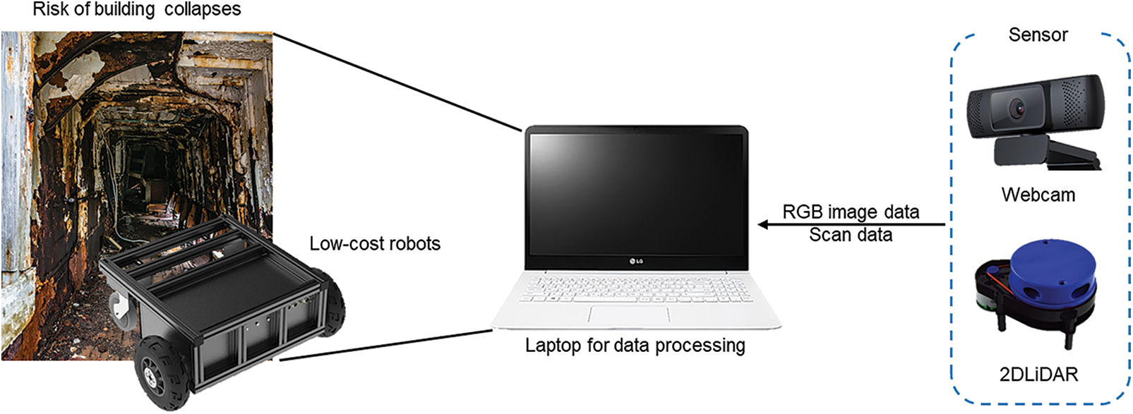
Figure 1: Architecture of data acquisition and processing system
Our system comprises two modules, as shown in Fig. 2. The first one is for an algorithm that detects the floor and obstacles via the camera and estimates the size of each obstacle, and the second one is for an algorithm that uses 2D-lidar to estimate the locations of the robots and obstacles, identify the surrounding environment, and create a map. The results of the created map and the detected obstacles are positioned on the map via the map update method. The sensors are connected based on the ROS. Meanwhile, the result of obstacle detection using the camera and the estimated size are combined with the results of locations estimated using Lidar. The ROS is a set of software libraries and tools for developing open-source-based robot software and building application programs on the robot. Fig. 3 shows an overall software architecture of the proposed algorithm. After obtaining the mask of the floor from the image obtained using the camera, we determined whether entry to the corridor was possible. If entry is possible, then the obstacles’ patterns are analyzed by obtaining the mask line. After estimating the obstacle sizes using the size estimation algorithm, we extract the shapes of the detect obstacles from the original frame and saved the obstacle shapes on the server. If an obstacle is detected, then the obstacle’s location is estimated using the range value of Lidar, and the corresponding section is displayed as an obstacle on the map. The digital map of the disaster site created based on the proposed algorithm is saved on the server, and the map can be used to assist efficient personnel deployment as well as search and rescue operations in a disaster situation.
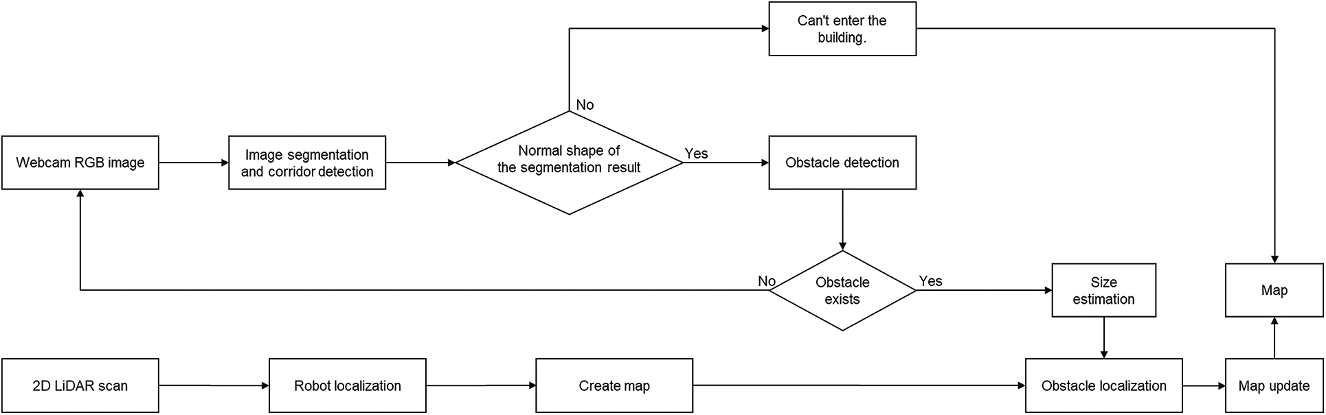
Figure 2: Proposed algorithm flow chart
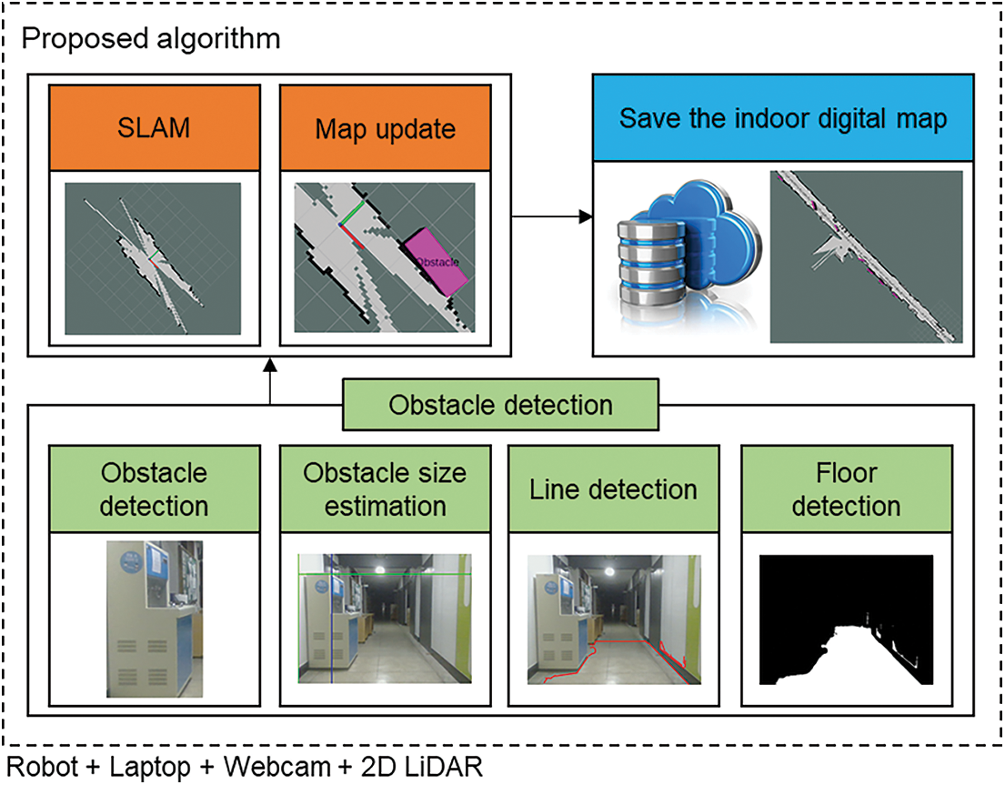
Figure 3: Software architecture for the proposed algorithm
3.3 Floor and Obstacle Detections
The proposed algorithm detects the floor to determine the possibility of entering the corridor and analyzes the edge line pattern of the floor to detect obstacles. In the subsections below, the floor detection and obstacle detection algorithms are described comprehensively.
Using Lidar, one can determine whether entry to a path obstructed by obstacles is possible, but not if the floor has collapsed. We can detect a collapsed floor by detecting the floor via a camera. Fig. 4 shows the floor detection algorithm proposed herein.
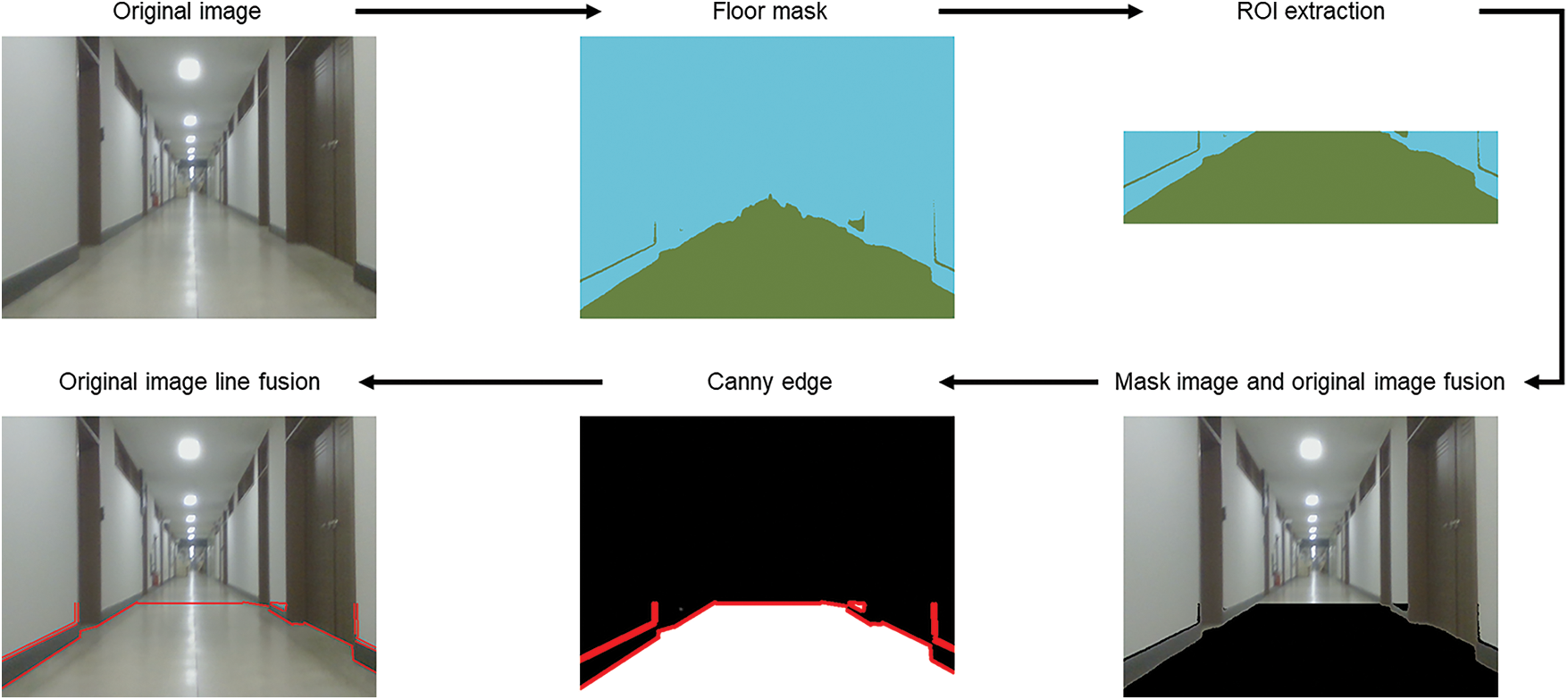
Figure 4: Flow diagram of floor detection algorithm
First, the model trained via the mask R-CNN is used to obtain the floor’s mask. The floor mask is triangular when no obstacle exists. However, because components that are distant cannot be determined accurately owing to the effect of light or shadows, we set two-thirds of the region as the region of interest (ROI). Additionally, unclear mask results are excluded, and the mask exhibits a trapezoidal shape. To analyze the pattern of the floor surface, we obtained the edge values from the mask using the canny edge [46]. In canny edge detection, a gaussian filter is used to remove the noise; subsequently, differential values are used to identify the edges. If the mask obtained by analyzing the pattern via the canny edge exhibits an abnormal shape that deviates from the normal shape, as shown in Fig. 5, then the corridor is regarded as impossible to enter.

Figure 5: Examples of normal and abnormal floor detection results
3.3.2 Obstacle Detection and Size Estimation
The floor’s patterns were analyzed to detect obstacles. If no obstacle exists, then a trapezoidal shape is observed, as shown on the left side of Fig. 6. However, if obstacles exist, then the patterns of the obstacles are reflected on the floor.

Figure 6: Examples of floor shapes without and with obstacles
If an edge differs from the normal edge, it is then assumed that an obstacle is present. When an obstacle was detected, we estimated the obstacle’s size using the proposed size estimation algorithm. We assumed that the x-axis value in the section that deviated the most from the normal lines among the determined edge values was the length of the obstacle’s base. Next, to estimate the obstacle’s height, we removed the region not required for estimating the object’s height. The point the where the y-coordinate becomes 0 based on the x-coordinate at the end section among the floor edges was designated as an unnecessary region. Since the corresponding section could not be identified clearly, we assumed that it was unrelated to the obstacle. After obtaining the edges by performing canny edge detection for the remaining image region after the removal, the line segment detector (LSD) [47] was used. The LSD determines straight lines as a rectangular region to detect lines, and if the pixels in the region are in the same direction, then they are classified as a straight line. This task can remove the features of all unnecessary spaces, such as the corridor’s gaps, and spaces with different contrasts; consequently, only the features of the obstacle remain. To obtain only the most vivid and distinct features among the edge values yielded by applying the LSD, we applied morphology techniques [48] to the edge values. The morphology techniques fill empty spaces or remove noise on the image to analyze the image’s shape. Consequently, the regions of various objects are displayed clearly on the image. Among the morphology techniques, the close operation is performed to remove unclear noises, and the open operation is performed to apply the values of the remaining features. The definite features obtained through this process include features of the endpoints of the obstacle. In particular, the feature at the uppermost section was used and designated as the obstacle’s height. Fig. 7 shows the overall process of the algorithm for detecting obstacles. We validated the obstacle detection algorithm by comparing the F1-score value of our proposed obstacle detection algorithm and those of conventional object detection algorithms.
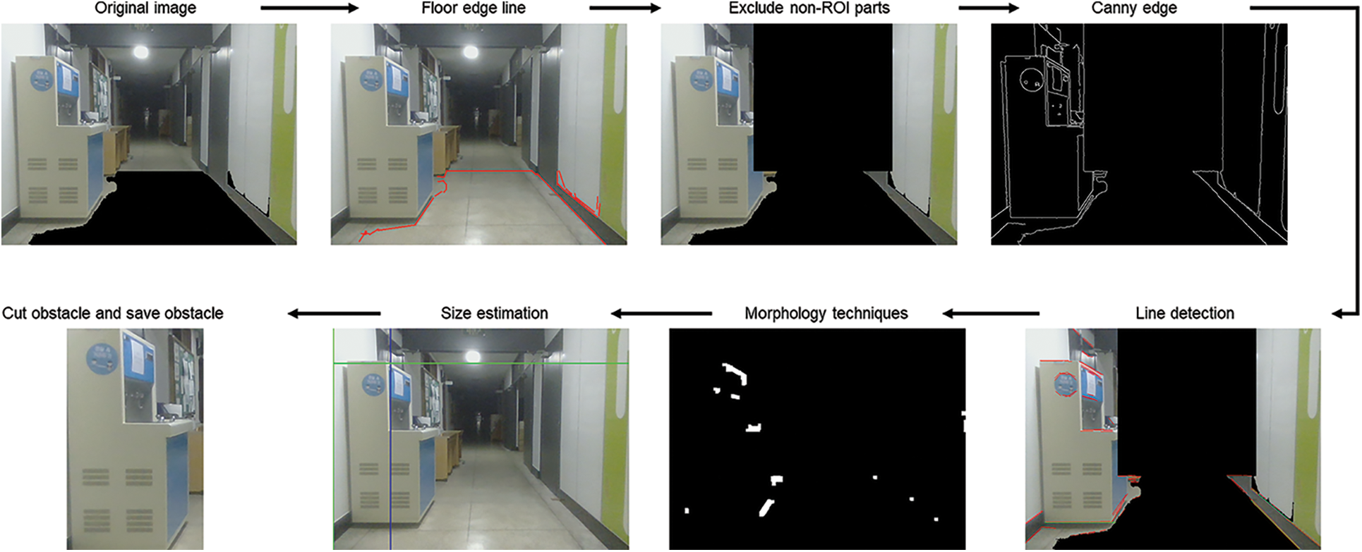
Figure 7: Overall process of obstacle detection and size-estimation algorithm
3.4 Floor Detection and Obstacle Detection
To match the scan values of Lidar and the obstacle’s position obtained using the camera, we installed the Lidar system and camera such that they were facing the same direction. Lidar estimates the robot’s location in the current space based on the robot’s movement and draws the map. If it detects an obstacle, then the scan values for the obstacle will appear, as shown in the green circle on the right side in Fig. 8.
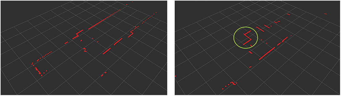
Figure 8: Lidar scan results without and with obstacle
Unlike the scan result without an obstacle, that with an obstacle is indented inward. The obstacle detected by the camera is matched with the indented section in the Lidar scan. We can identify the obstacle’s location by matching the results of the camera with those of Lidar. Unlike the camera, Lidar may not scan the obstacle based on location. Fig. 9 shows the result of the map without obstacles and that of updating the map with obstacles. The detected obstacle is marked by a red circle. To update the obstacles on the map, we used the map update algorithm suggested in semantic SLAM. After performing a comparison to determine whether obstacles exist on the map, the map update algorithm adds an object if an obstacle does not exist on the current map. If an obstacle exists, then it is replaced by another object, or the current state is maintained based on its accuracy via a comparison with the existing value. In the case of semantic SLAM, the object is detected and displayed on the map via the SSD algorithm. However, in this study, the obstacles detected using the proposed method are positioned on the map. We compared the map generated via semantic SLAM and that generated using the SLAM proposed herein via experiments for validation; subsequently, we generated a map that can be used in an actual disaster site.
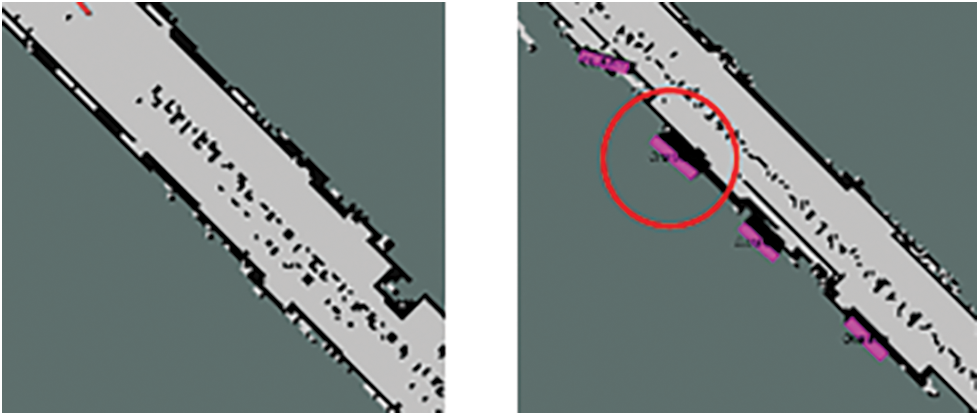
Figure 9: Examples of mapping result without obstacles (left); mapping result with obstacle marked by red circle (right)
In our study, the initial position of the robot must be set. The initial position inside the disaster building is identified based on the robot’s initial position. Meanwhile, the places that can be entered, stairs, and rooms are distinguished based on the robot’s position. The robot’s initial position can be directly specified by the user and estimated automatically based on the room number, etc. from the robot’s place of entry. Furthermore, as the robot traverses, its position is estimated via SLAM. If the position cannot be estimated because the robot is wobbling excessively, then the robot’s position can be reset when the robot changes the direction via a staircase and a corner based on the architectural drawing. Furthermore, even without a change in direction, the robot’s position can be reset via the room number, etc. detected as the robot traverses. This is facilitated by an indoor localization algorithm associated with position resetting [49].
In this section, the experimental design and results are detailed.
The setup of the robot for the experiments is shown in Fig. 10. The robot can be controlled using a remote controller, and data are obtained using the camera and 2D-lidar embedded in the laptop computer. Subsequently, the data are processed using the modules of the proposed algorithm installed in the laptop computer. The camera used was an LG camera with a video graphics array (VGA) that measured 640 × 480. The 2D-lidar system offers a range distance of 0.12–10 m and a scan frequency of 6–12 Hz. It detects objects by rotating 360° and has an angle resolution of 0.43° to 0.86°. The laptop computer used for data processing was an LG Gram 15z980-ga50k (equipped with an eighth-generation i5-8250U central processing unit (CPU), a double data rate 4 (DDR4) 8 GB memory, and the Ubuntu 18.04LTS operating system).
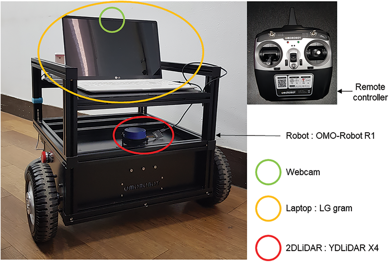
Figure 10: Setup of robot for experiments
Tab. 1 shows the results of obstacle detection yielded by proposed algorithm and conventional algorithms. The conventional algorithms detected objects in the corridor via models trained using the COCO dataset [50], in which labels were assigned to 80 different objects. The obstacle detection algorithm designed in this study detected more diverse obstacle shapes as compared with the other algorithms compared.
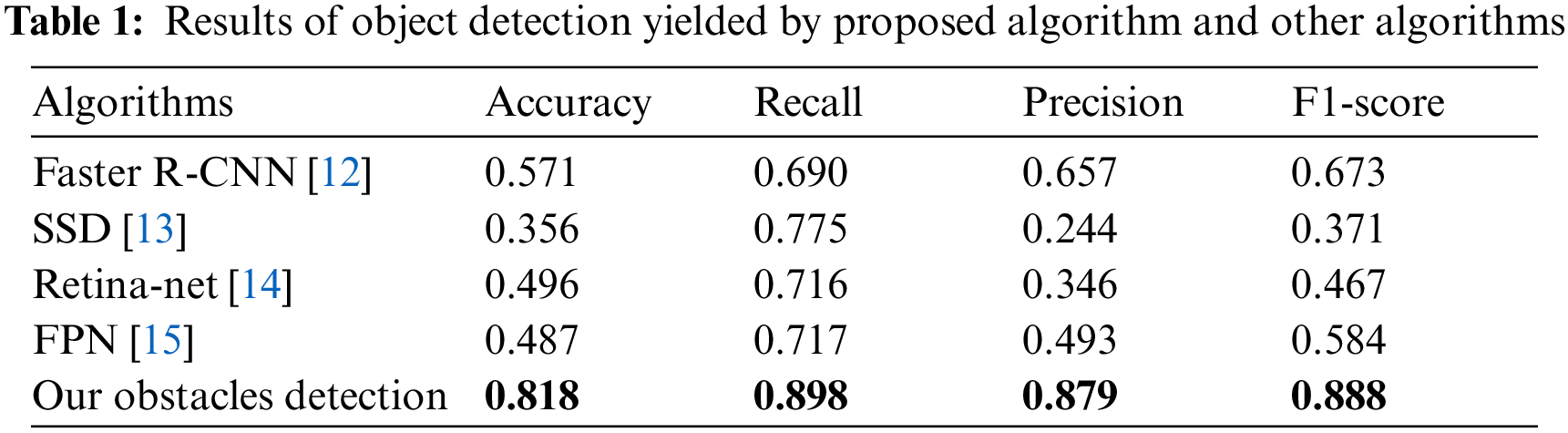
The conventional object detection algorithms detect only objects that have been learned, whereas the obstacle detection algorithm proposed herein detects various shapes of objects that have been learned and not learned. Because our goal is to propose an algorithm that can be used in disaster sites, we designed an algorithm that can detect various shapes of obstacles that may exist in disaster sites. In this study, the proposed algorithm’s performance was validated based on the level of obstacles in the actual space, as well as the created map and the conventional semantic SLAM method. Eight obstacles were set in the experimental space. The obstacles that continued consecutively were regarded as one obstacle, and the results are shown in Tab. 2. The semantic SLAM detected only one obstacle because it detected only objects that were learned by the SSD model. However, the SLAM method used in our study detected eight obstacles. Additionally, the execution time of the method was faster than that of the semantic SLAM. However, the execution time was proportional to the number of detected obstacles. Therefore, the algorithm proposed herein required a longer execution time than the conventional semantic SLAM because it detected all obstacles. We expressed the execution time in second (s).
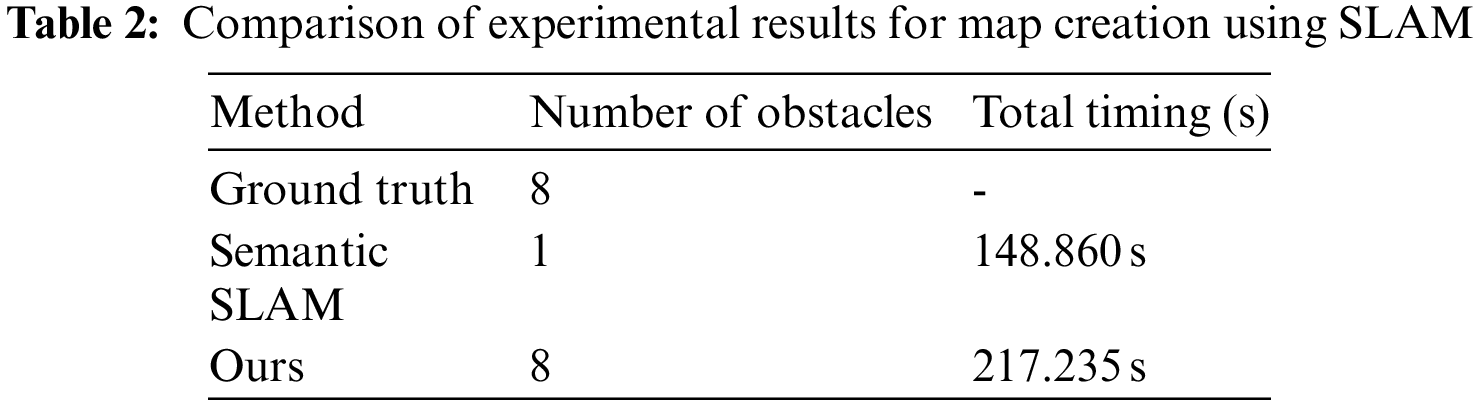
Fig. 11 shows the created maps. The semantic SLAM on the left side detected only the object in the area marked by a red circle, whereas the algorithm proposed herein detected various obstacles. Unlike the conventional semantic SLAM, which detects 10 designated objects via only a trained SSD model, the proposed algorithm detects various obstacles based on their patterns. Because various shapes of obstacles that cannot be learned exist in an actual disaster situation, it is impossible to create a model trained with all obstacles. Therefore, maps generated in this study will be more effective in disaster situations.
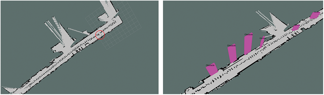
Figure 11: Result of maps generated using conventional semantic SLAM (left) and proposed SLAM (right)
In this study, we constructed a digital map of a disaster site to understand the disaster situation in a building to facilitate efficient search and rescue operations. We used an entry-level robot, a low-cost camera, and 2D-lidar to conduct experiments. In the experiments, our obstacle detection algorithm demonstrated a higher accuracy as compared with conventional object detection algorithms, and its SLAM result for the disaster site was more similar to the ground truth in the building compared with the results of conventional semantic SLAM. In semantic SLAM, obstacles are detected based on objects that have been learned, after which they are displayed on the map. However, the algorithm proposed herein detects various shapes of obstacles that has or has not been learned and then displays them on the map. Furthermore, inexpensive entry-level robots and devices can be used to operate more easily in disaster situations, as compared with expensive firefighting robots developed to date. The algorithm’s accuracy was prioritized in this study; however, in the future, we will conduct a study to increase the system’s efficiency. We hope that this study—which involves obstacle detection in various disaster sites and yields disaster SLAM results—will be beneficial to firefighters and operations in actual disaster sites.
Funding Statement: This research was supported by Basic Science Research Program through the National Research Foundation of Korea funded by the Ministry of Education (No. 2020R1I1A3068274), Received by Junho Ahn. https://www.nrf.re.kr/ .
Conflicts of Interest: The authors declare that they have no conflicts of interest to report regarding the present study.
References
1. M. Ahrens and B. Evarts, “Fire loss in the United States during 2020,” National Fire Protection Association (NFPAMA, USA: NFPA Research, 2021. [Online]. Available: https://www.nfpa.org//-/media/Files/News-and-Research/Fire-statistics-and-reports/US-Fire-Problem/osFireLoss.pdf. [Google Scholar]
2. D. Bailey, D. Brown, A. L. González, M. Hills, T. Housden et al., “Miami building collapse: What happened, and how quickly?,” BBC, London, UK: BBC News, 2021. [Online]. Available: https://www.bbc.com/news/world-us-canada-57609620. [Google Scholar]
3. S. Petherick, “Remains of grenfell tower may be pulled down after fire that killed 72,” METRO, London, UK: Metro news, 2021. [Online]. Available: https://metro.co.uk/2021/05/12/remains-of-grenfell-tower-might-be-pulledhttps://-down-after-fire-that-killed-72-14562219/#metro-comments-container. [Google Scholar]
4. Y. H. Seok, “Ha, end robot, around the disaster scene. safety to humans,” Electronic Newspapers Internet, Seoul, Korea: Etnews, 2021. [Online]. Available: https://news.v.daum.net/v/20210725180107826. [Google Scholar]
5. E. Ackerman and E. Guizzo, “Centauro: A new disaster response robot from IIT,” IEEE Spectrum, NY, USA: Institute of Electrical and Electronics Engineers, 2018. [Online]. Available: https://spectrum.ieee.org/centauro-a-new-disaster-response-robot-from-iit. [Google Scholar]
6. J. Ramos, A. Wang and K. Sangbae, “Human reflexes help MIT’s hermes rescue robot keep its footing,” IEEE Spectrum, NY, USA: Institute of Electrical and Electronics Engineers, 2019. [Online]. Available: https://spectrum.ieee.org/human-reflexes-help-mits-hermes-rescue-robot-keep-its-footing. [Google Scholar]
7. S. Kohlbrecher, O. Stryk, J. Meyer and U. Klingauf, “A flexible and scalable SLAM system with full 3D motion estimation,” in IEEE Int. Symp. on Safety, Security, and Rescue Robotics (SSRR), Kyoto, Japan, pp. 155–160, 2011. [Google Scholar]
8. O. Tslil, A. Elbaz, T. Feiner and A. Carmi, “Representing and updating objects’ identities in semantic SLAM,” in IEEE 23rd Int. Conf. on Information Fusion (FUSION), Rustenburg, South Africa, pp. 1–7, 2020. [Google Scholar]
9. G. Brazil and X. Liu, “M3d-RPM: Monocular 3D region proposal network for object detection,” in IEEE/CVF Int. Conf. on Computer Vision (ICCV), Los Alamitos, CA, USA, pp. 9286–9295, 2019. [Google Scholar]
10. M. Elhoseny, “Multi-object detection and tracking (MODT) machine learning model for real-time video surveillance systems,” Circuits Syst Signal Process, vol. 39, no. 2, pp. 611–630, 2020. [Google Scholar]
11. A. Bochkovskiy, C. Wang and H. M. Liao, “YOLOv4: Optimal speed and accuracy of object detection,” arXiv preprint arXiv:2004.10934, 2020. [Google Scholar]
12. S. Ren, K. He, R. Girshick and J. Sun, “Faster R-CNN: Towards real-time object detection with region proposal networks,” IEEE Transactions on Pattern Analysis and Machine Intelligence, vol. 39, no. 6, pp. 1137–1149, 2017. [Google Scholar]
13. W. Liu, D. Anguelov, D. Erhan, C. Szegedy, S. Reed et al., “SSD: Single shot multibox detector,” in Computer Vision–ECCV 2016, Cham, Switzerland: Springer, vol. 9905, pp. 21–37, 2016. [Google Scholar]
14. T. Y. Lin, P. Goyal, R. Girshick, K. He and P. Dollar, “Focal loss for dense object detection,” in 2017 IEEE Int. Conf. on Computer Vision (ICCV), Venice, Italy, pp. 2980–2988, 2017. [Google Scholar]
15. T. Y. Lin, P. Dollár, R. Girshick, K. He, B. Hariharan et al., “Feature pyramid networks for object detection,” in IEEE Conf. on Computer Vision and Pattern Recognition (CVPR), Honolulu, HI, USA, pp. 936–944, 2017. [Google Scholar]
16. L. Byongkwon, K. Sookyun and K. Seokhun, “A study on pagoda image search using artificial intelligence(AI) technology for restoration of cultural properties,” KSII Transactions on Internet and Information Systems, vol. 15, no. 6, pp. 2086–2097, 2021. [Google Scholar]
17. H. Yang, S. Kang, C. Park, J. Lee, K. Yu et al., “A hierarchical deep model for food classification from photographs,” KSII Transactions on Internet and Information Systems, vol. 14, no. 4, pp. 1704–1720, 2020. [Google Scholar]
18. S. Emani, K. P. Soman, V. V. S. Variyar and S. Adarsh, “Obstacle detection and distance estimation for autonomous electric vehicle using stereo vision and DNN,” in Soft Computing and Signal Processing: Proc. of ICSCSP 2018, NY, USA: Springer, vol. 2, ch. 65, pp. 639–648, 2019. [Google Scholar]
19. W. Shubo, W. Ling, H. Xiongkui and C. Yi, “A monocular vision obstacle avoidance method applied to indoor tracking robot,” Drones, vol. 5, no. 4, pp. 1–15, 2021. [Google Scholar]
20. L. Steccanella, D. D. Bloisi, A. Castellini and A. Farinelli, “Waterline and obstacle detection in images from low-cost autonomous boats for environmental monitoring,” Robotics and Autonomous Systems, vol. 124, pp. 103346, 2020. [Google Scholar]
21. K. He, G. Gkioxari, P. Dollár and R. Girshick, “Mask R-CNN,” in 2017 IEEE Int. Conf. on Computer Vision (ICCV), Venice, Italy, pp. 2961–2969, 2017. [Google Scholar]
22. A. Jabbar, X. Li, M. M. Iqbal and A. J. Malik, “FD-stackGAN: Face de-occlusion using stacked generative adversarial networks,” KSII Transactions on Internet and Information Systems, vol. 15, no. 7, pp. 2547–2567, 2021. [Google Scholar]
23. S. Lei, Y. Kailun, H. Xinxin, H. Weijian and W. Kaiwei, “Real-time fusion network for RGB-D semantic segmentation incorporating unexpected obstacle detection for road-driving images,” arXiv preprint arXiv:2002.10570, 2020. [Google Scholar]
24. F. A. L. Reis, R. Almeida, E. Kijak, S. Malinowski, S. J. F. Guimarães et al., “Combining convolutional side-outputs for road image segmentation,” in Int. Joint Conf. on Neural Networks (IJCNN), Budapest, Hungary, pp. 1–8, 2019. [Google Scholar]
25. R. Fan and M. Liu, “Road damage detection based on unsupervised disparity map segmentation,” IEEE Transactions on Intelligent Transportation Systems, vol. 21, no. 11, pp. 4906–4911, 2020. [Google Scholar]
26. M. Lan, Y. Zhang, L. Zhang and B. Du, “Global context based automatic road segmentation via dilated convolutional neural network,” Information Sciences, vol. 535, pp. 156–171, 2020. [Google Scholar]
27. Z. Xiaopin, L. Weibin, X. Weiwei and W. Xiang, “DA-Res2net: A novel densely connected residual attention network for image semantic segmentation,” KSII Transactions on Internet and Information Systems, vol. 14, no. 11, pp. 4426–4442, 2020. [Google Scholar]
28. S. Gu, Y. Zhang, J. Tang, J. Yang and H. Kong, “Road detection through CRF based lidar-camera fusion,” in Int. Conf. on Robotics and Automation (ICRA), Montreal, QC, Canada, pp. 3832–3838, 2019. [Google Scholar]
29. L. Zheng, P. Zhang, J. Tan and F. Li, “The obstacle detection method of UAV based on 2D lidar,” IEEE Access, vol. 7, pp. 163437–163448, 2019. [Google Scholar]
30. J. Azeta, C. Bolu, D. Hinvi and A. A. Abioye, “Obstacle detection using ultrasonic sensor for a mobile robot,” in 8th Int. Conf. on Mechatronics and Control Engineering, Paris, France, pp. 012012, 2019. [Google Scholar]
31. D. Jia, M. Steinweg, A. Hermans and B. Leibe, “Self-supervised person detection in 2D range data using a calibrated camera,” in IEEE Int. Conf. on Robotics and Automation (ICRA), Xi’an, China, pp. 13301–13307, 2021. [Google Scholar]
32. A. Mulyanto, R. I. Borman, P. Prasetyawana and A. Sumarudin, “2D lidar and camera fusion for object detection and object distance measurement of ADAS using robotic operating system (ROS),” JOIV: International Journal on Informatics Visualization, vol. 4, no. 4, pp. 231–236, 2020. [Google Scholar]
33. Y. Wang, W. L. Chao, D. Garg, B. Hariharan, M. Campbell et al., “Pseudo-lidar from visual depth estimation: Bridging the gap in 3D object detection for autonomous driving,” in IEEE Int. Conf. Computer Vision and Pattern Recognition (CVPR), Long Beach, CA, USA, pp. 1–16, 2019. [Google Scholar]
34. V. S. Kalogeiton, K. Ioannidis, G. C. Sirakoulis and E. B. Kosmatopoulos, “Real-time active SLAM and obstacle avoidance for an autonomous robot based on stereo vision,” Cybernetics and Systems, vol. 50, no. 3, pp. 239–260, 2019. [Google Scholar]
35. F. H. Ajeil, I. K. Ibraheem, M. A. Sahib and A. J. Humaidi, “Multi-objective path planning of an autonomous mobile robot using hybrid PSO-MFB optimization algorithm,” Applied Soft Computing, vol. 89, no. C, pp. 1–13, 2020. [Google Scholar]
36. S. Gatesichapakorn, J. Takamatsu and M. Ruchanurucks, “ROS based autonomous mobile robot navigation using 2D lidar and RGB-D camera,” in First Int. Symp. on Instrumentation, Control, Artificial Intelligence, and Robotics (ICA-SYMP), Bangkok, Thailand, pp. 151–154, 2019. [Google Scholar]
37. H. Ramdane and B. Messaoudm, “Real-time obstacle avoidance for a swarm of autonomous mobile robots,” International Journal of Advanced Robotic Systems, vol. 11, no. 67, pp. 1–12, 2014. [Google Scholar]
38. A. B. Alhassan, X. Zhang, H. Shen and H. Xu, “Power transmission line inspection robots: A review, trends and challenges for future research,” International Journal of Electrical Power & Energy Systems, vol. 118, pp. 105862, 2020. [Google Scholar]
39. Y. Xiong, Y. Ge, L. Grimstad and P. J. From, “An autonomous strawberry-harvesting robot: Design, development, integration, and field evaluation,” Journal of Field Robotics, vol. 37, no. 2, pp. 202–224, 2019. [Google Scholar]
40. T. Sabhanayagam, T. Kumar, M. Narendra and J. Sahayaraj, “Internet connected modern fire fighting robot,” Journal of Physics: Conference Series, vol. 1964, no. 4, pp. 042088, 2021. [Google Scholar]
41. F. G. Hoffman, “The first firefighting robot in america is here--and it has already helped fight a major fire in Los Angeles,” CNN Business, GA, USA: BBC, 2020. [Online]. Available: https://edition.cnn.com/2020/10/21/business/first-firefighting-robot-in-america-lafd-trnd/index.html. [Google Scholar]
42. “OMOROBOT,” OMO R1. [Online]. Available: https://omorobot.com/docs/omo-r1/, 2021, Oct, 19. [Google Scholar]
43. LG, LG gram 15z980-ga50k. [Online]. Available: https://www.lge.co.kr/support/product-manuals, 2018. [Google Scholar]
44. YDLIDAR, YDLIDAR X4. [Online]. Available: https://www.ydlidar.com/products/view/5.html, 2021, Jul, 22. [Google Scholar]
45. ROS, ROS Melodic Morenia. [Online]. Available: http://wiki.ros.org/melodic, 2018, May, 23. [Google Scholar]
46. J. Canny, “A computational approach to edge detection,” IEEE Transactions on Pattern Analysis and Machine Intelligence, vol. PAMI-8, no. 6, pp. 679–698, 1986. [Google Scholar]
47. R. G. v. Gioi, J. Jakubowicz, J. Morel and G. Randall, “LSD: A line segment detector,” Image Processing on Line (IPOL), vol. 2, pp. 35–55, 2012. [Google Scholar]
48. R. M. Haralick, S. R. Sternberg and X. Zhuang, “Image analysis using mathematical morphology,” IEEE Transactions on Pattern Analysis and Machine Intelligence, vol. PAMI-9, no. 4, pp. 532–550, 1987. [Google Scholar]
49. J. Ahn and R. Han, “Rescueme: An indoor mobile augmented-reality evacuation system by personalized pedometry,” in 2011 IEEE Asia-Pacific Services Computing Conf., Jeju, Korea, pp. 70–77, 2011. [Google Scholar]
50. Common Objects in Context, COCO Dataset 2017 test images. [Online]. Available: http://images.cocodataset.org/zips/test2017.zip, 2017. [Google Scholar]
Cite This Article
 Copyright © 2023 The Author(s). Published by Tech Science Press.
This work is licensed under a Creative Commons Attribution 4.0 International License , which permits unrestricted use, distribution, and reproduction in any medium, provided the original work is properly cited.
 Downloads
 Citation Tools