DOI:10.32604/cmc.2022.025527
| Computers, Materials & Continua DOI:10.32604/cmc.2022.025527 | |
| Article |
A Compact Flexible Circularly Polarized Implantable Antenna for Biotelemetry Applications
1Department of Signal Theory and Communications, Universidad Carlos III de Madrid, Madrid, 28911, Spain
2Department of Telecommunication Engineering, University of Engineering and Technology, Peshawar, 25120, Pakistan
3Department of Electrical and Electronic Engineering, Auckland University of Technology, Auckland, 1010, New Zealand
*Corresponding Author: Sarosh Ahmad. Email: saroshahmad@ieee.org
Received: 26 November 2021; Accepted: 28 December 2021
Abstract: With the help of in-body antennas, the wireless communication among the implantable medical devices (IMDs) and exterior monitoring equipment, the telemetry system has brought us many benefits. Thus, a very thin-profile circularly polarized (CP) in-body antenna, functioning in ISM band at 2.45 GHz, is proposed. A tapered coplanar waveguide (CPW) method is used to excite the antenna. The radiator contains a pentagonal shape with five horizontal slits inside to obtain a circular polarization behavior. A bendable Roger Duroid RT5880 material (εr = 2.2, tanδ = 0.0009) with a typical 0.25 mm-thickness is used as a substrate. The proposed antenna has a total volume of 21 × 13 × 0.25 mm3. The antenna covers up a bandwidth of 2.38 to 2.53 GHz (150 MHz) in vacuum, while in skin tissue it covers 1.56 to 2.72 GHz (1.16 GHz) and in the muscle tissue covers 2.16 to 3.17 GHz (1.01 GHz). GHz). The flexion analysis in the x and y axes was also performed in simulation as the proposed antenna works with a wider bandwidth in the skin and muscle tissue. The simulation and the curved antenna measurements turned out to be in good agreement. The impedance bandwidth of −10 dB and the axis ratio bandwidth of 3 dB (AR) are measured on the skin and imitative gel of the pig at 27.78% and 35.5%, 13.5% and 4.9%, respectively, at a frequency of 2.45 GHz. The simulations revealed that the specific absorption rate (SAR) in the skin is 0.634 and 0.914 W/kg in muscle on 1g-tissue. The recommended SAR values are below the limits set by the federal communications commission (FCC). Finally, the proposed low-profile implantable antenna has achieved very compact size, flexibility, lower SAR values, high gain, higher impedance and axis ratio bandwidths in the skin and muscle tissues of the human body. This antenna is smaller in size and a good applicant for application in medical implants.
Keywords: ISM band; implantable antenna; biotelemetry; circularly polarized; flexible antenna
In-body devices play a key role in improving the daily lives of patients [1]. With in-body antennas, the biotelemetry system has given lots of benefits, including high data-rates and long-range connections [2,3]. The main features of the proposed CP antenna design are in-body medical equipments [4]. In the medium frequency range (402–405 MHz) [5–7], and in the ISM frequency range (2.4–2.48 GHz) [8–13], many native CP antennas have been planned for communication in wireless systems. Reference [14] described a small broadband antenna for biomedical implants that operates in the MICS band (403 MHz). The non-conducting layer was a Roger 6010 semi-bendy material with a 1.27 mm-height. SAR values of 284.5 W/kg at 1 g were determined, which is significantly higher than our stated design. Reference [15] proposed a new biomedical ISM antenna for in-body purposes created on a polyimide material. The antenna had a peak gain of −16.8 dB and a working band-range of 1.22%. The total antenna size was 2520 mm2. On the required frequency, the obtained gain and working band-range were recorded at −34.9 dB and 14.9% respectively. References [16,17] reported multiband antennas for the ISM band purposes. Reference [18] described a small CP antenna for biological purposes with improved matching. The ground plane has an X-shaped slot, and the radiating array is circular. Rogers 3010 was employed as the substrate, and it was 0.634 mm thick. The antenna profile is thicker than our proposed design [19] due to the two-layer substrate. However, the antenna was not biologically compatible with the individual body and had SAR value of approximately 649 W/kg, which is still above the IEEE/IEC 6270-1 limit of 1g mass of tissue. A circular CP antenna with AR of 19.1% has been reported for medical purposes in [20]. This stated design made with dual flexible layers of Roger 3010, each of 0.635 mm thick. The antenna worked at 2.45 GHz in the ISM band, with an operating band-range of 8%. The value of SAR for the design, worked in muscle tissue, were calculated to be 508 W/kg, exceeding the standard limit. The maximum antenna gain was −17.5 dB. As the design was larger than our presented antenna, also no twisting analysis were performed. Another work in [21], described a CPW-powered implantable split ring resonator-based design for biological purposes. The complete size was found to be 2422 mm2 and the bendy polyimide material with 0.07 mm thick was used. The antenna had a low profile and could be tested in vitro. Compared to our proposed antenna, the antenna was still quite large. At 2.45 GHz, the realized gain, and optimum band range were −19.7 dB and 24.4%, respectively.
This paper illustrates a bendable in-body CP antenna design with a volume of 21 × 13 × 0.25 mm3 for biomedical purposes working in the ISM band (at 2.45 GHz). The antenna has an elliptical radiation pattern in the E-plane and omnidirectional in the H-plane at 2.45 GHz. The in-body antenna is compact and flexible, which allows it to work better inside body. The proposed antenna uses modified coplanar waveguide (CPW) technology, which reduces SAR and back radiation values. The stated design covers a wider band-range at 2.45 GHz due to the recent patch and CPW modification, and its maximum gain is comparable to recent research Under the impact of the physical body, the effectiveness and act of the proposed antenna have increased and the SAR values greatly reduced The paper is distributed in four sections: The first section presents the research topic, traces the history of the proposed study, the description of the research objectives and the meaning of the study. Design analysis of the proposed system is discussed in Section 2. The production and measurement results, as well as the testing of the antenna in skin and muscle tissues, are described in Section 3 and the conclusion is presented in Section 4.
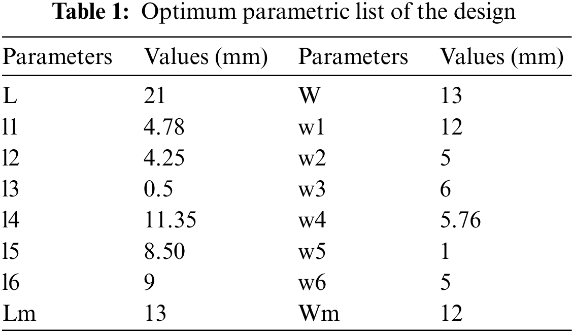
A compact monopole slotted antenna with a pentagonal radiator in coplanar waveguide (CPW) technique is stated. The suggested design contains a flat printed monopole with a flexible Roger RT5880 substrate of 0.25 mm thick as shown in Fig. 1. Roger RT5880 is a known material for its low profile and stability in folded conditions. The total size of the antenna is 21 × 13 × 0.25 mm3. The antenna shown was simulated employing CST simulator and the antenna’s S11 value was observed to be −31.985 dB at an operating band of 2.45 GHz. The impedance and the AR band-range of the presented antenna seem to be 5.73% and 13.46%, correspondingly. The optimal parameters of this design are shown in Tab. 1.
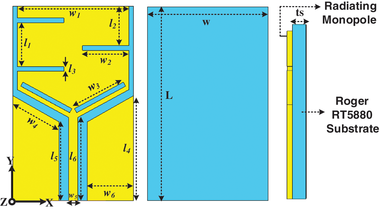
Figure 1: In-body antenna design structure
2.1 Stated Structure Design Steps
The model procedure for the in-body antenna is demonstrated in Fig. 2. The design steps of the antenna help to find out the optimized parameters to achieve optimum values in terms of S11 and the axial ratio bandwidths. The proposed design can be performed in three steps; in the first step (ANT I), a rectangular radiator is proposed to achieve a reflection coefficient of −10 dB, but it resonates only at 2.7 GHz and in this case, it has no circular polarization. The length and width of the radiating monopole (13 × 12 mm2) are denoted by ‘Lm’ and ‘Wm’, respectively. In the second step (ANT II) (Fig. 2a), the rectangular monopole is truncated at its lower edges to change the frequency toward the desired band and to achieve CP. This lowers the resonant frequency to 2.6 GHz (100 MHz) while maintaining the S11 below −10 dB at 2.55 GHz and AR band-range of 8.1%. In the step 3 (ANT III), the CPW ground of the truncated rectangular monopole is modified to achieve a good AR bandwidth of 10.2%, but the frequency is at 2.55 GHz with a characteristic band-range of 120 MHz. Thus, to shift the band to a lower band (up to 2.45 GHz) with improved AR, horizontal slots are introduced in the truncated rectangular monopole, as shown in ANT IV. In the instance of ANT IV, the stated design displays an AR band-range of 13.46% and works completely at 2.45 GHz with a improved band-range of 140 MHz. The simulated S11 plot and the plot of the axis-to-frequency ratio of the entire design process is shown in Fig. 2b, demonstrating how easy it is to match the impedance at 2.45 GHz with the CPW technique.
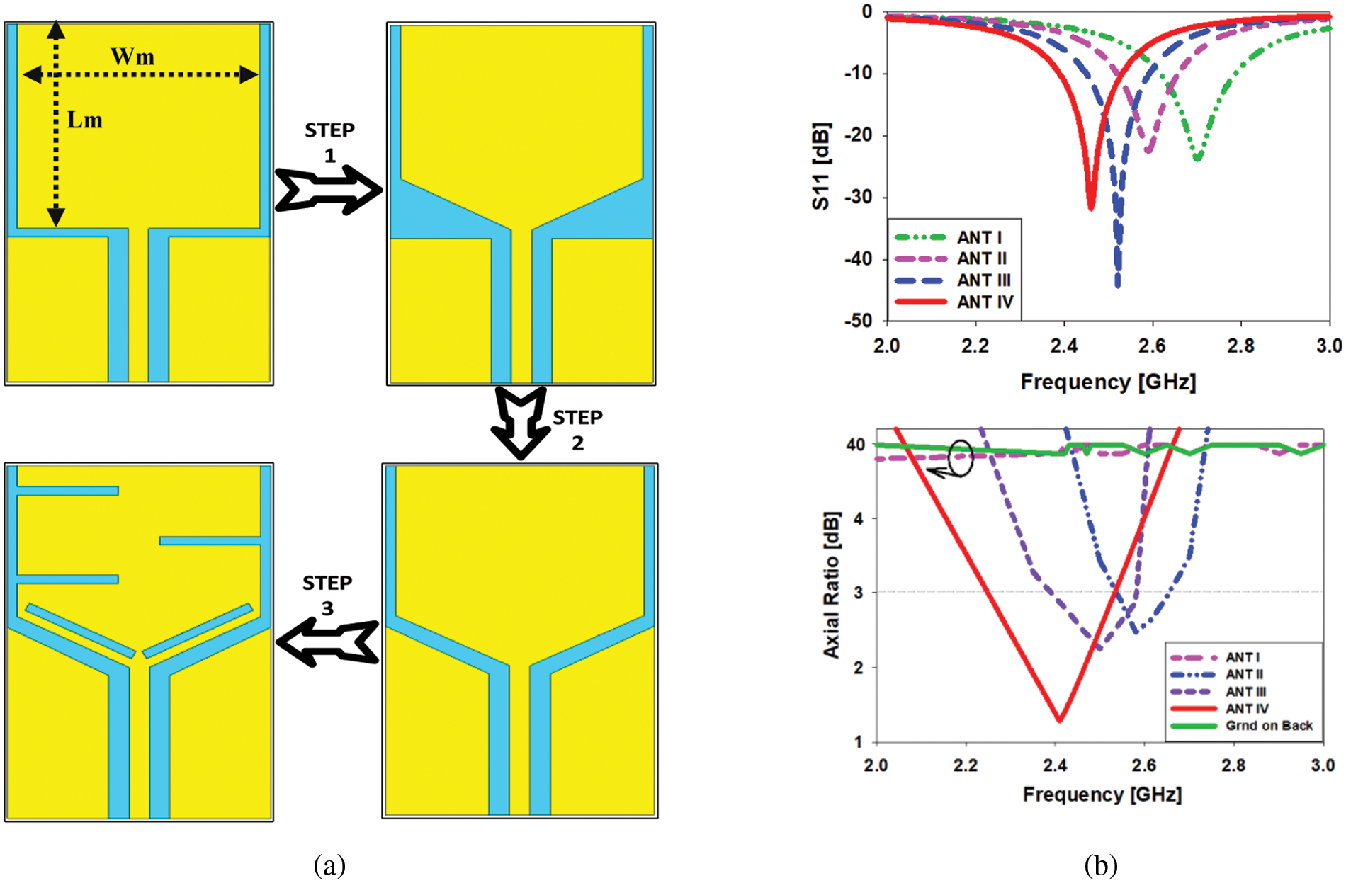
Figure 2: (a) Printed antenna design procedure, (b) comparison of S11 and the axial ratio in [dB]
This section explains in detail how to analyze the parameters of the implanted antenna. The width of the monopole ‘w1 = wm’, feedline’ width ‘w5’, CPW ground’ width ‘w6’, length of the upper length of the monopole ‘l2’, CPW ground’ length ‘l5’, length of the horizontal slit ‘l3’, width of the slit ‘w2’, and width of the rotated slit ‘w3’ as shown in Fig. 3. The frequency band was changed from 2.6 to 2.45 GHz (150 MHz) by changing the value of ‘w1’ from 16 to 20 mm as shown in Fig. 3a. The frequency band changed 2.2–2.63 GHz (430 MHz) when the value of ‘w5’ changed 0.5–1.5 mm, as shown in Fig. 3b. The frequency band increased 2.45–2.39 GHz (60 MHz) when the values of ‘w6’ increased 3–6 mm, as shown in Fig. 3c. The frequency changes from 2.45 to 2.6 GHz (150 MHz) when the value of ‘l2’ changes from 5.25–7.25 mm, as shown in Fig. 3d. The band was changed 2.45–2.82 GHz (370 MHz) by increasing the value of ‘l5’ 7–9 mm, as shown in Fig. 3e. Optimization of the radiator slots is now also considered. The frequency band was increased 2.45–2.7 GHz (250 MHz) with a reduction in return loss when the length and width of the horizontal slot ‘l3’ was increased from 0.5–1.25 mm, as shown in Fig. 3f. As shown in Fig. 3g, the frequency was increased 2.5–2.81 GHz (310 MHz) by reducing the width of the ‘w2’ slot from 6.5–4.5 mm. Finally, the width of the ‘w3’ rotation slot has been optimized. It was found that by reducing the value of ‘w3’ 6–4 mm, the frequency could be increased 2.5–2.8 GHz (300 MHz), as shown in Fig. 3h.
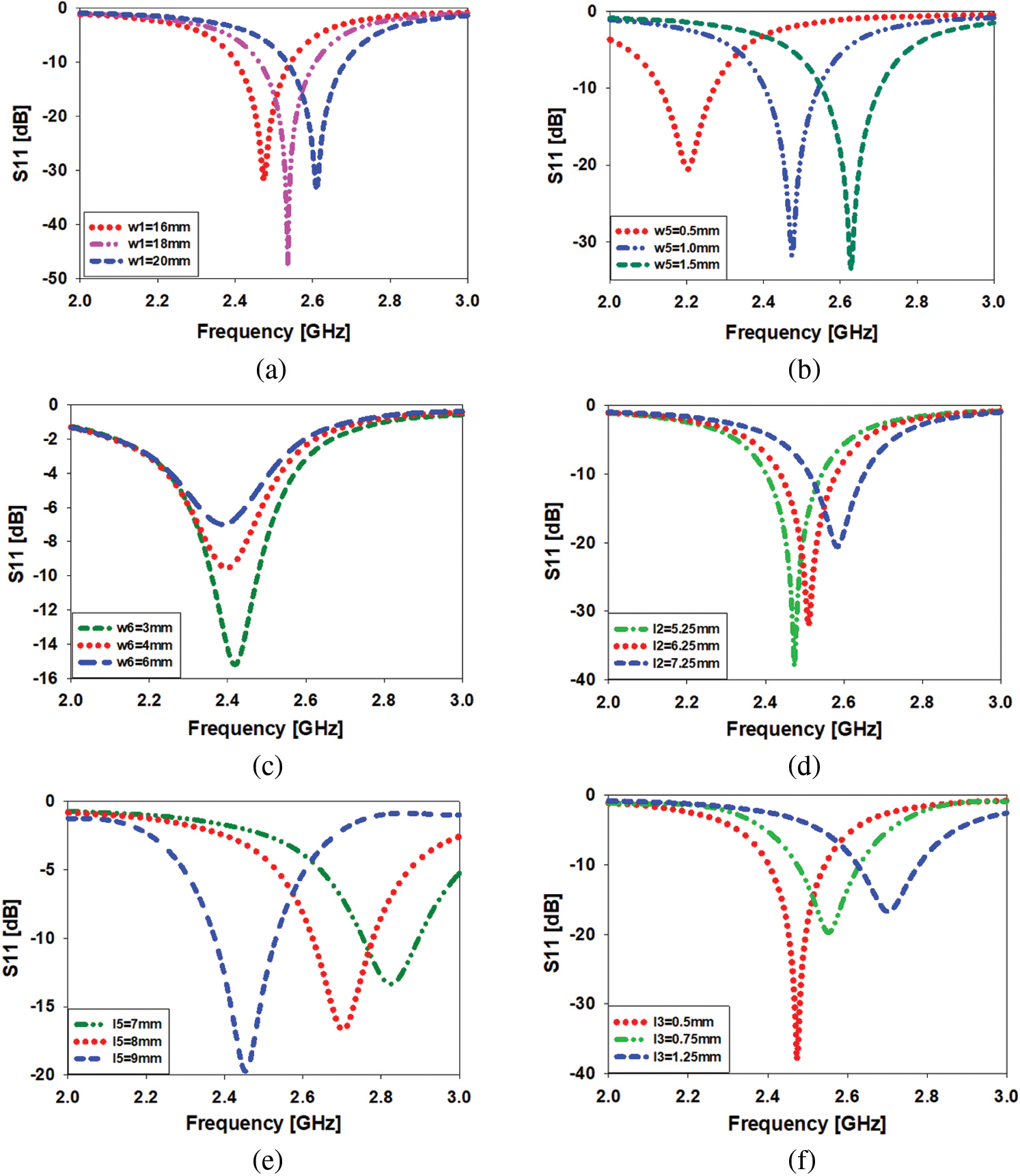
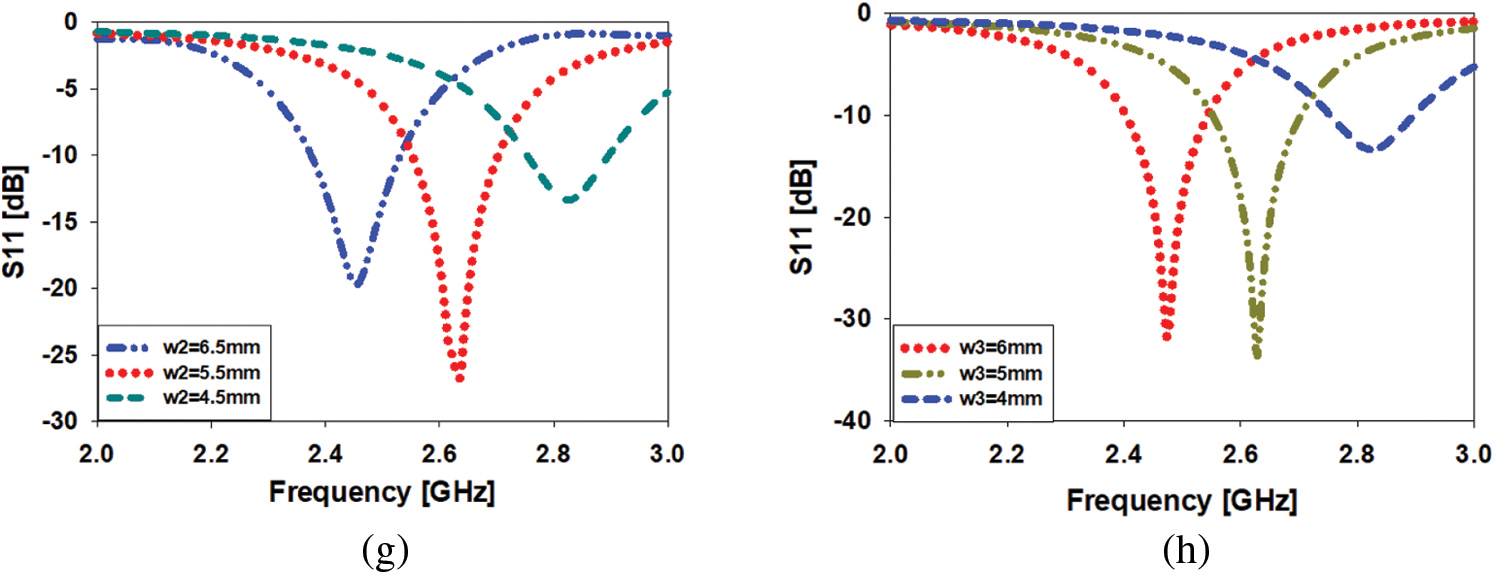
Figure 3: Study of parameters; (a) changes in ‘w1’, (b) changes in ‘w5’, (c) changes in ‘w6’, (d) changes in ‘l2’, (e) changes in ‘l5’, (f) changes in ‘l3’, (g) changes in ‘w2’, (h) changes in ‘w3’
3 Manufactured Model of the Stated Design
The proposed implantable design was printed on a flexible Roger RT5880 material with 0.25 mm thick profile; front and back view of the constructed prototype are displayed in Fig. 4a. In an anechoic chamber, the radiation pattern is measured, and the experimental frame is presented in Fig. 4b. In the far field evaluation anechoic chamber, we use the stated design and the proposed radio frequency (RF) absorber to absorb the RF signals from the device in the anechoic chamber. A VNA is used to verify the implantable antenna S11. The stated design covers the band-range 2.39–2.53 GHz (140 MHz) at 2.45 GHz in the case of the simulated results and the band-range 2.35–2.55 GHz (200 MHz) at 2.45 GHz in the case of the measured reflection coefficient, as shown in Fig. 4c.
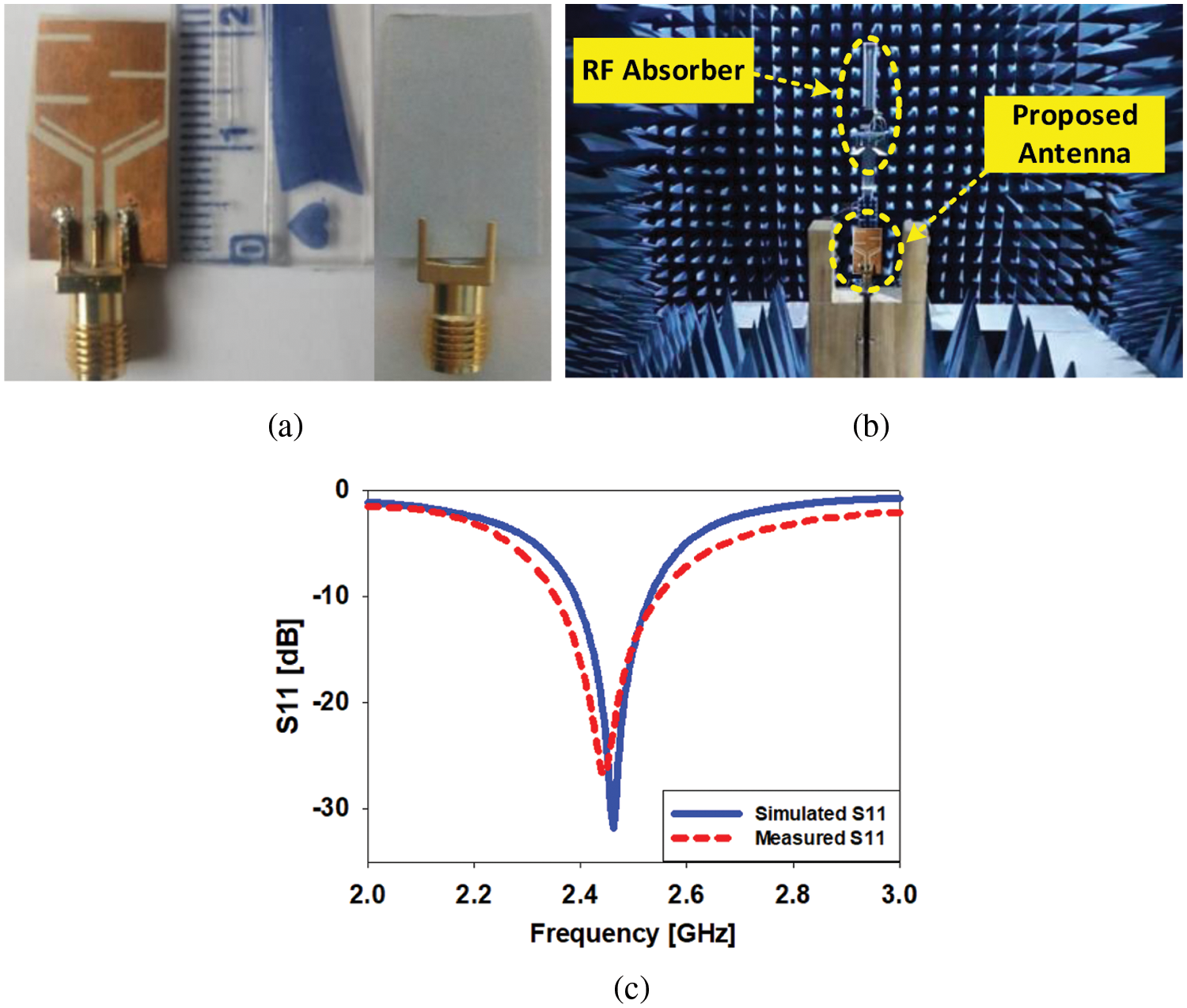
Figure 4: (a) Prototype fabricated antenna, (b) antenna setup inside anechoic chamber, (c) assessment between the simulated and experimental S11 [dB] in free space
In vacuum, the (E & H) levels of the design are validated and experimentally checked (see Fig. 5a). The performance of the antenna is described by its two-dimensional (2D) radiation pattern. At 2.45 GHz, the proposed antenna radiates an elliptical pattern in the E-plane and an omnidirectional in the H-plane. At 2.45 GHz, the proposed antenna has simulated and measured gain of −2.5 dB and −2.7 dB, respectively. Fig. 5b provides the current density of the implanted antenna. The coplanar waveguide power line (CPW), the ground plane and the lower slots where most of the current flows. When current flows in a circular path through the printed monopole, the characteristics of circular polarization are demonstrated. Fig. 6 shows the maximum gain graph and a contrast among the measured and simulated axis ratios. The simulated antenna in vacuum covers the AR band-range from 2.25 to 2.53 GHz (11.42%) at 2.45 GHz, while the prototype covers the AR band-range 2.3 to 2.53 GHz (9.38%) at 2.45 GHz.
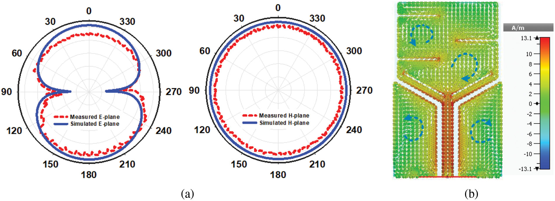
Figure 5: (a) Two-dimensional pattern of the design in vacuum at 2.45 GHz, (b) Surface current distribution
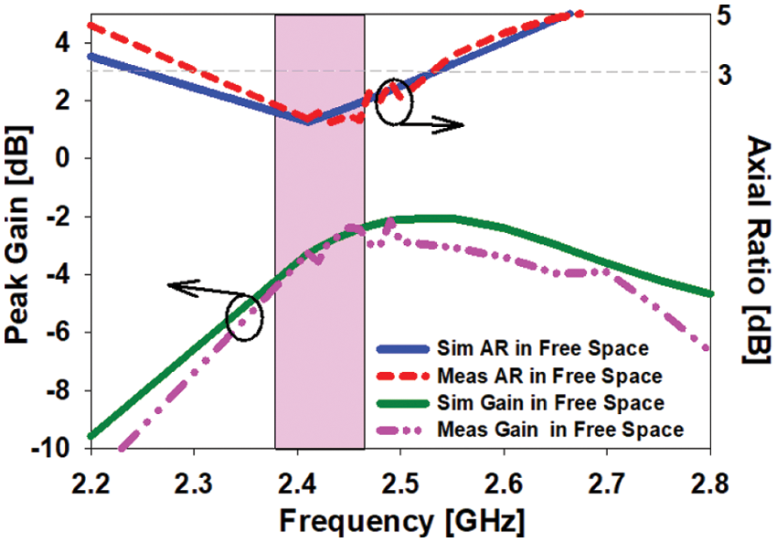
Figure 6: Difference in the simulations and the experimentally validated gain and the axial ratio vs. frequency graph
As the design is manufactured by using a bendy Roger material RT5880, it is needed to study the antenna deflection along the horizontal and vertical axes to confirm the S11 of the prototype when it is not folded. In implanted conditions, the antenna is essentially based on bending. The assessment of the antenna deflection along the x and y axes in vacuum is described in detail in this section. Flexural analyzes are not only based on simulations, but also measured using a cylinder-shaped foam with a radius of 30 mm. Bending analysis along the x and y axes demonstrates both the stability and flexibility of the antenna [22]. Therefore, the antenna scattering parameters in human tissues may not change when folded. Therefore, it is necessary to test the stability of the antenna as it is made of flexible material.
Different radii of curvature are chosen along the x-axis Bx = 20–100 mm to study the behavior of the S11, the maximum gain and the pattern of the antenna. Fig. 7a relates the simulated results of the antenna folded along the x-axis. It is recognized that all radii of curvature undergo unnecessary changes and the peak gain attained with the radiation pattern at 2.45 GHz decreases significantly. The difference of the AR of the curved antenna alongside the x-axis is demonstrated in Fig. 7b.
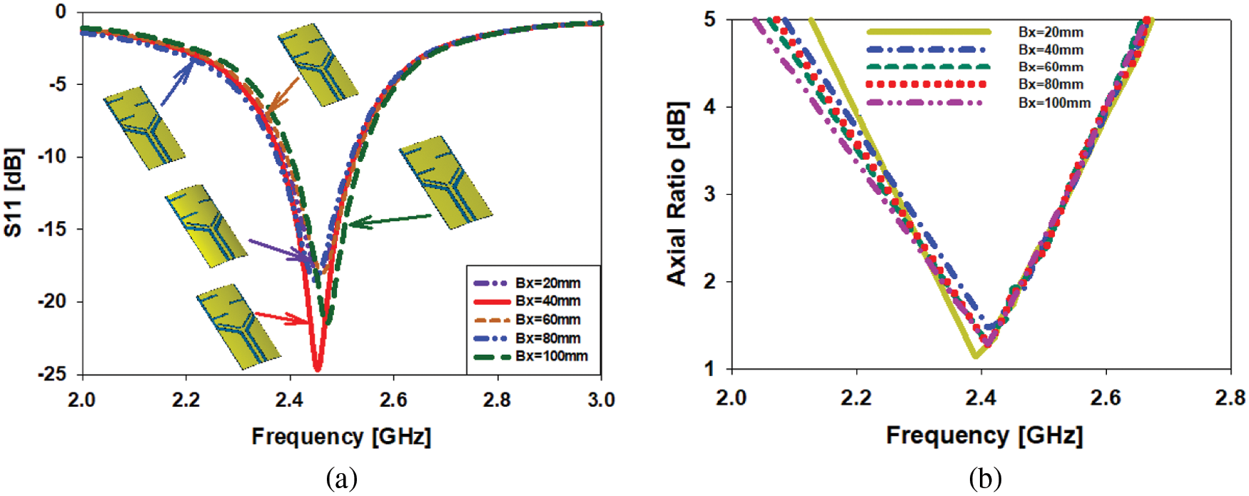
Figure 7: Bending study of the antenna along x-axis at 2.45 GHz; (a) difference in S11, (b) difference in AR
When folded along the x-axis, the reflection coefficient of the proposed biomedical implantable printed unipolar antenna is not only modelled, but also measured. When folded along the x-axis (Bx = 30 mm), Fig. 8 illustrates the contrast between the simulated and measured S11. The folded antenna covers the band-range from 2.38–2.53 GHz (150 MHz) to 2.45 GHz in the computed result, whereas the antenna covers the band-range from 2.34–2.49 GHz (150 MHz) to 2.45 GHz in the measured result.
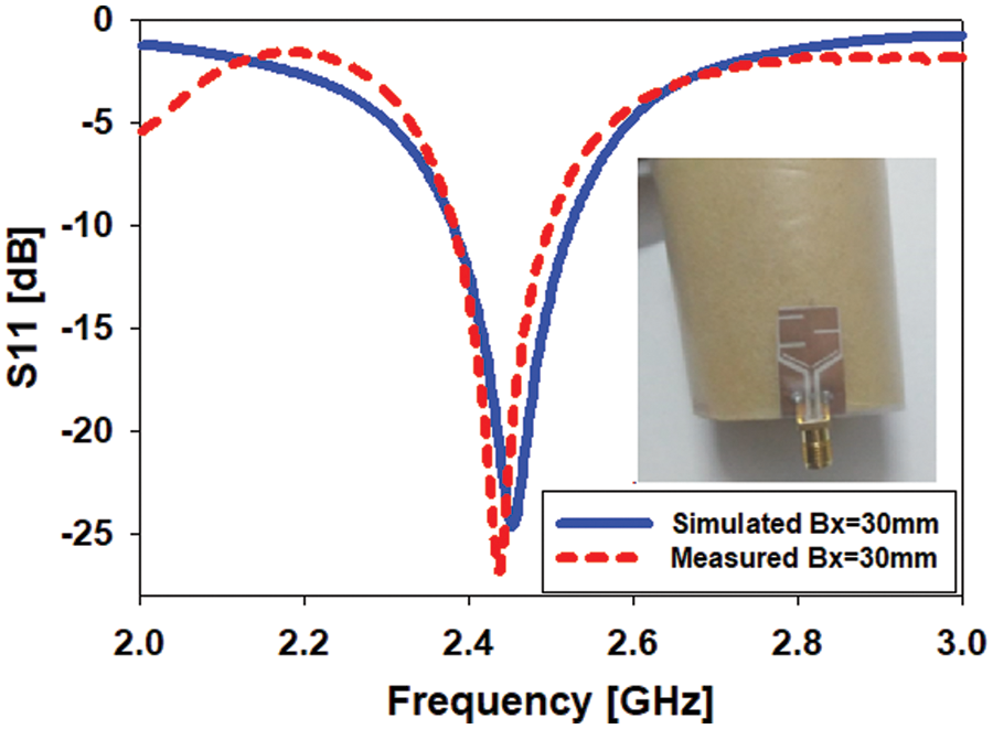
Figure 8: Bending of the antenna and S11 behavior when Bx = 30 mm
To authenticate the S11 behavior, the acquired gain, and the antenna’s radiation pattern, several values of radii of curvature (curvature along the y axis ‘By’ = 20–100 mm) are used. In Fig. 9a, the antenna modeling results are compared when folded along the y axis. There are minimal changes in all radii of curvature, and the gain achieved with the radiation pattern at 2.45 GHz gradually decreases. Fig. 9b shows a comparison of the axial ratio of an antenna bent along the y axis. The axis ratio values change somewhat when folded along the y axis, as seen in the diagram. The AR value is less than 3 dB and the antenna works perfectly at 2.45 GHz.
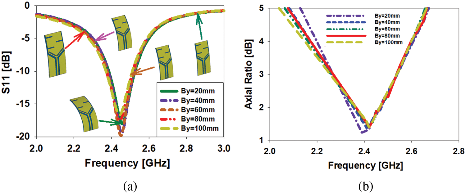
Figure 9: Deflection study of the antenna along y-axis at 2.45 GHz; (a) difference in S11, (b) difference in AR
When the suggested flexible implantable antenna is bent along the y-axis, the S11 is simulated and measured. The difference between simulated and observed S11 when bent along the y-axis (By = 30 mm) is shown in Fig. 10. The folded antenna covers the band-range of 2.39–2.52 GHz (130 MHz) at 2.45 GHz in the computed result, whereas the antenna covers the band-range of 2.40–2.49 GHz (90 MHz) at 2.45 GHz in the measured result.
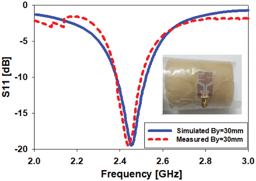
Figure 10: Bending of the antenna and S11 behavior when By = 30 mm
4 Antenna Testing Inside Human Tissues
This section simulates and evaluates the suggested antenna design in a human body phantom model to see if it is suitable for biomedical telemetry applications. As a result, when building an antenna for high-precision biotelemetry applications, the existence of tissues must be considered while estimating SAR. The antenna’ act in near-body phantoms and the SAR values at 2.45 GHz are also considered for this objective. As indicated in Fig. 11, the 3D box has a surface size of 50 x 50 mm2. The phantoms utilized in the testing are made up of three layers of tissue: skin, fat, and muscle. Tab. 2 shows their thickness and 2.45 GHz properties. The stated design was tested in the tissue layers in two ways, namely skin and muscle. CST Microwave Studio is employed to simulate the proposed antenna.
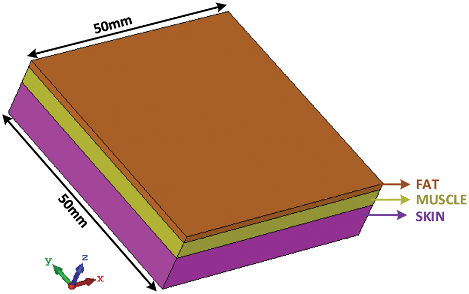
Figure 11: Human body phantoms box
4.1 Testing Inside Skin Mimicking Gel
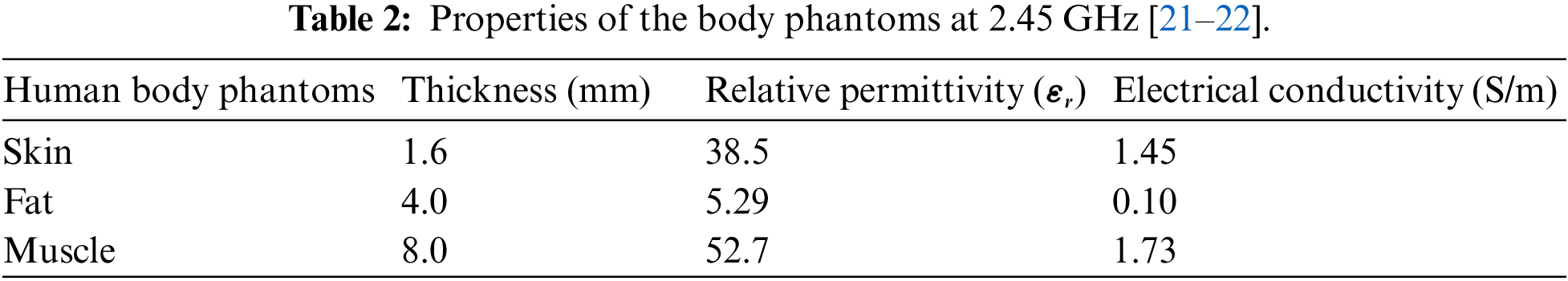
Ideally, endogenous antennas are proposed to minimize the strong effects of coupling affected by human tissue. The antenna will be implanted 0.75 mm deep into the skin tissue while examination, as displayed in Fig. 12. The proposed design is simulated over a 50 mm × 50 mm area with different layers of human tissue to estimate these effects. As shown in Tab. 2, it consists of a layer of skin (1.6 mm-thickness), fat (4 mm-thickness), and muscle tissue (8 mm-thickness). To calculate the radiation pattern and S11 of the presented design in the skin, a “skin-like gel” with an εr of 46 is used (see Fig. 12a) because its values are near to human skin tissue. To prepare a solution of the “skin-like gel”, the amount and percentage of the ingredients of the gel such as sucrose (53%), deionized water (47%), and sodium chloride (NaCl) solution are adjusted to 40 ml in a beaker with a magnetic stirrer and stimulated for 15 min. Then, 0.5 g of dry carbomer was added in a liquid solution to form a ‘skin-like gel’. The solution was then heated to 81°C for 59 min to obtain a neat mixture. The solutions were then coagulated by chilling to room temperature before being measured [19]. Fig. 12b depicts the discrepancy among the simulated and measured S11 of the antenna in the skin. The biological antenna works from 2.16 to 3.17 GHz (41.22 percent) at 2.45 GHz, whereas the produced antenna in the imitating gel has bandwidths from 2.17 to 2.85 GHz, according to the simulated S11 value in the skin (27.75 percent).
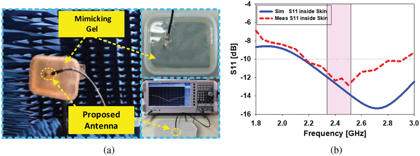
Figure 12: (a) Investigational framework to determine pattern and S11, (b) comparison of S11 inside skin tissue
The modeling and measurement findings of the radiation pattern in skin tissue in the (E&H) plane is shown in Fig. 13. The two-dimensional pattern defines the activity of the antenna inside the skin. The antenna under the skin features a wide-area omnidirectional radiation pattern in the E-plane and an elliptical radiation pattern along the H-plane, according to these far-field observations at 2.45 GHz. The simulated realized gain within the skin at 2.45 GHz is −14.3 dB, whereas measurement findings reveal a realized gain of −13.8 dB. Fig. 14 depicts the axial ratio and realized gain inside the skin as modelled and measured. The AR band-range of the simulated antenna in the skin tissue is 2.18 to 2.53 GHz (14.2 percent) at 2.45 GHz, whereas the manufactured antenna in the skin-like gel is 2.19 to 2.52 GHz (13.5 percent) at 2.45 GHz.
Figure 13: Two-dimensional pattern at 2.45 GHz inside skin tissue
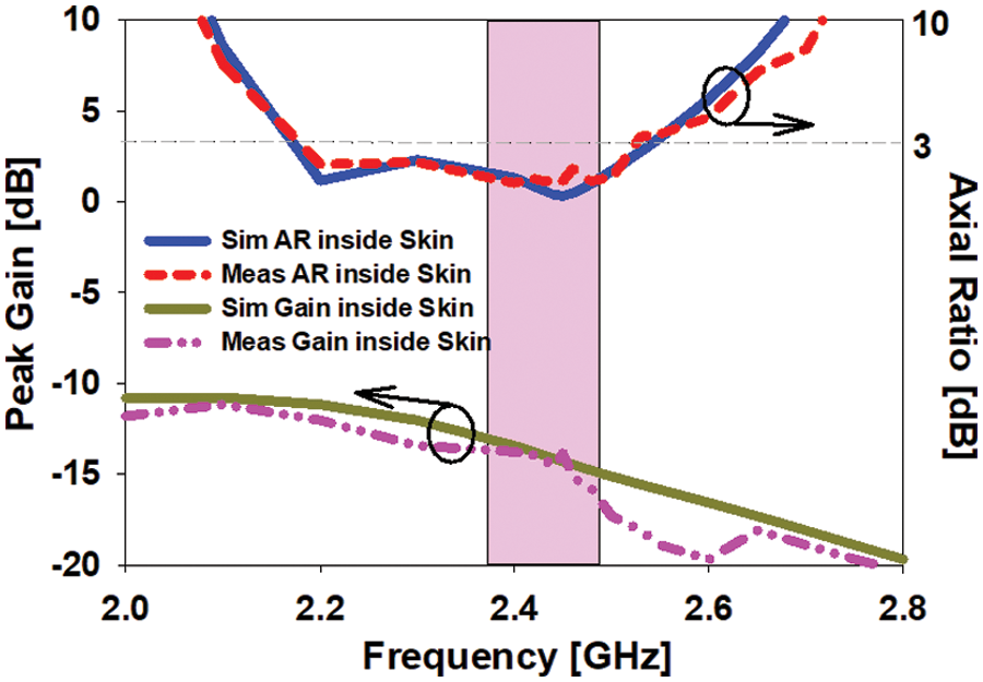
Figure 14: Difference in the simulation and experimental gain and the AR inside skin
To simulate and test the flexible implantable antenna in human muscle tissue, the antenna is kept 2 mm deep in muscle tissue. Fig. 15 shows the simulation evaluation setup and radiation pattern measurement in the anechoic chamber and S11 measurement in tissue with VNA. Since, in the situation of the simulation outcomes, the antenna is tested inside the human muscle tissue, while in the case of the experimental outcomes the antenna is measured inside the pork phantom whose properties are very similar to human muscle tissue. Antenna S11 is simulated in human muscle tissue and measured in pork and their comparison is indicated in Fig. 15b. The simulation results of the implantable antenna in human muscle tissue indicate an operating bandwidth of 1.56 to 2.72 GHz (47.3%) to 2.45 GHz. The antenna prototype in the pork, on the other hand part, it featured bandwidths from 1.82 to 2.69 GHz (35.5%) to 2.45 GHz, which shows that the simulated S11 is close to the measured S11.
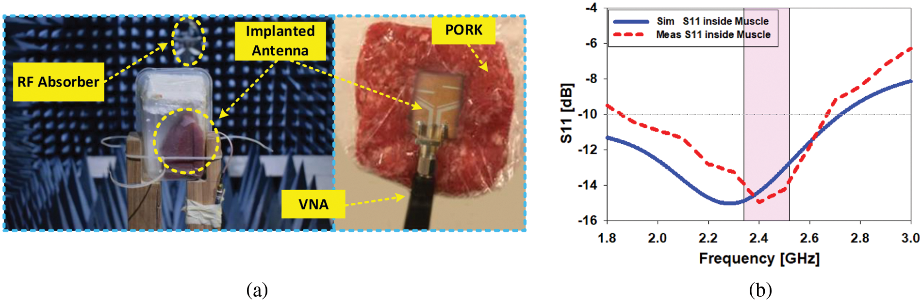
Figure 15: Antenna testing setup inside muscle of human tissue, (b) contrast among the simulated and measured S11 inside muscle tissue
The planes (E and H) of the simulated radiation pattern observed inside the muscle are shown in Fig. 16. The 2D radiation pattern defines the antenna performance inside the muscle. These far-field results demonstrate that the antenna within the muscle has broad directional radiation patterns in both planes in the 2.45 GHz frequency band. The simulation results also showed maximum gain within the muscle. of −16.1 dB at 2.45 GHz, while the realized gain is determined by the measurement results of −15.8 dB at 2.45 GHz. Fig. 17 shows the graphs of simulated and measured gain and axial ratio performed within the muscle tissue. At 2.45 GHz, the simulated antenna within muscle tissue covers an AR band-range of 2.37 to 2.5 GHz (5.3%), while the antenna manufactured within the pig covered an AR band-range of 2.39 to 2.51 GHz (4.9%).
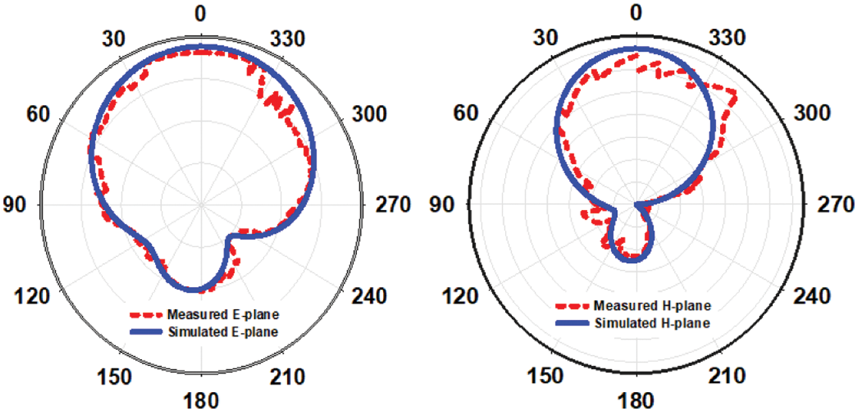
Figure 16: Simulated and measured farfield results at 2.45 GHz inside muscle tissue
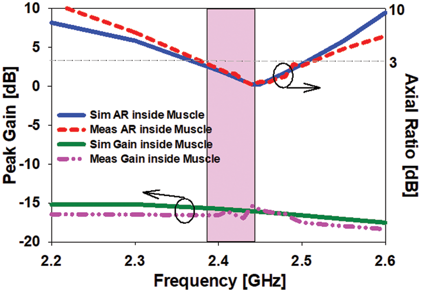
Figure 17: Assessment of the of gain and the axial ratio of the prototype inside muscle tissue
The radiation of EM-waves can produce hazards to the health of the body and these hazards are computed by means of SAR. The relation among input power and SAR is as follows [10]:
where,
SAR simulations were performed when the stated design is held in skin and muscle. The input power pin was held constant at 0.05 mW with an estimated SAR for IEEE/IEC 6270-1 be close to 1 g tissue mass. Calculated SAR values at 2.45 GHz are 0.634 W/kg in skin tissue and 0.914 W/kg in muscle tissue, as indicated in Fig. 18. Suggested antenna performance is compared to recent studies in Tab. 3.
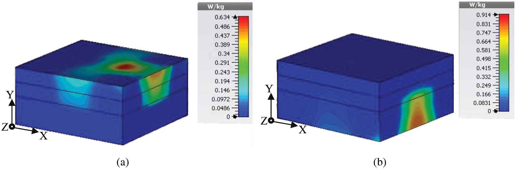
Figure 18: SAR distribution of the proposed antenna at 2.45 GHz over 1 g; (a) inside skin tissue, (b) inside muscle tissue
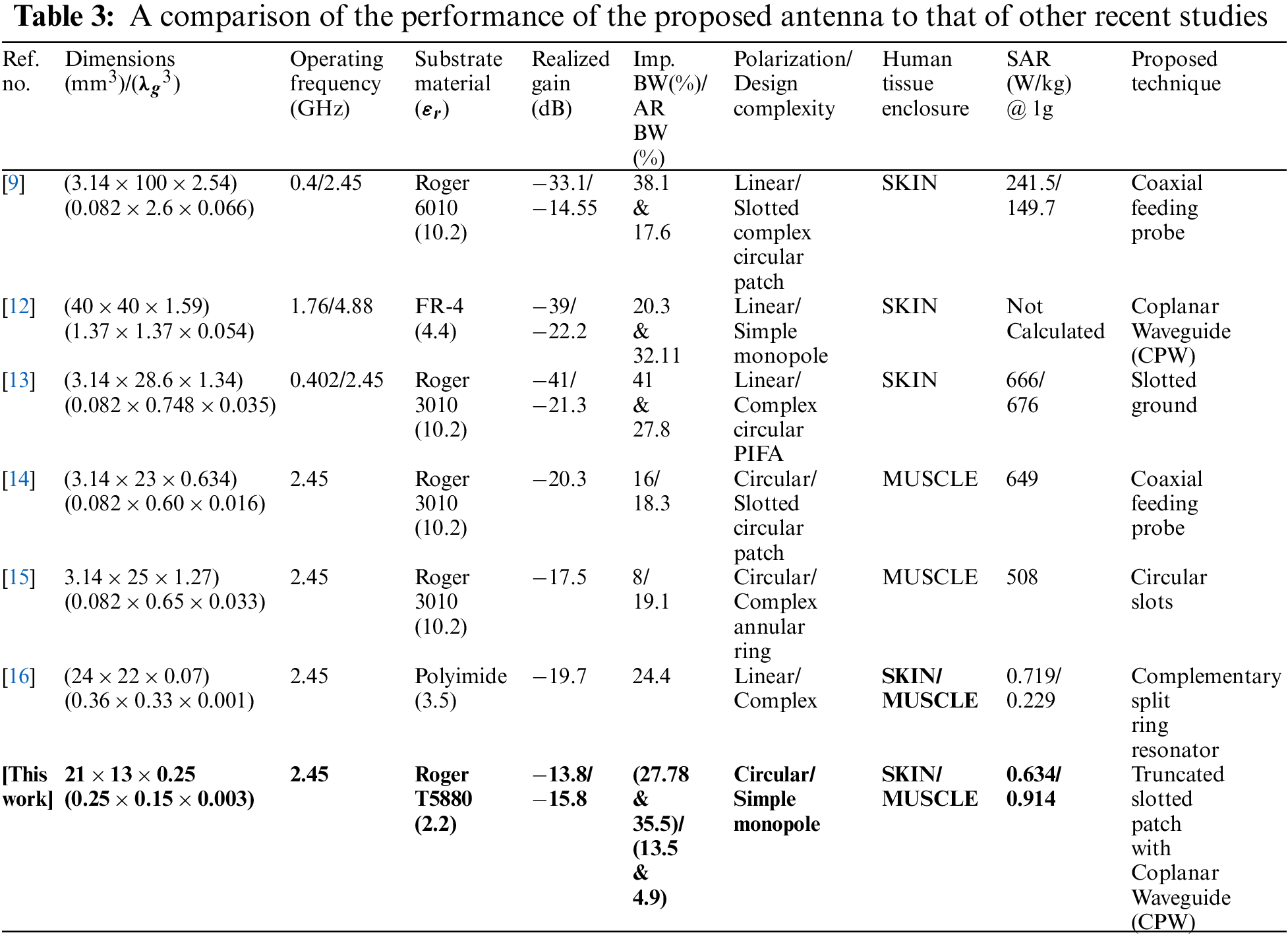
This work presents a printed unipolar antenna with a small footprint for biomedical implant applications. Computer Simulation Technology (CST) software was used to simulate the design. This antenna resonates at 2.45 GHz in the ISM band. The antenna is manufactured of RT/Duroid 5880 and has overall dimensions of 21 mm × 13 mm × 0.25 mm. The measured gain of the antenna within the skin and the skin mimicking gel is considered as −13.8 and −15.8 dB correspondingly, while the measured band-range of the antenna is testified as 35.5% and 27.78% inside skin and muscle tissues, correspondingly and the AR band-range are estimated by experimentation as 13.5% inside mimicking gel and 4.9% inside pork. SAR values are smaller than the FCC standards, which are 0.634 W/kg within the skin and 0.914 W/kg within the muscles. Biocompatibility and safety compliance issues related to medical building applications were also addressed. As it is clear from the above results that the antenna showed much lower values than the SAR values, this antenna is applicable for biomedical telemetry applications and is useful in doctor-patient communication. This antenna is miniaturized and is an appropriate candidate for portable biomedical purposes. Additionally, it is suggested to improve the antenna gain within human tissues as well as to reduce the SAR values to make the antenna biocompatible.
Funding Statement: The authors received no specific funding for this study.
Conflicts of Interest: The authors declare that they have no conflicts of interest to report regarding the present study.
1. H. H. Tran, K. Nam and N. Hussain, “Single-layer wideband circularly polarized antenna using non-uniform metasurface for C-band applications,” Computers, Materials & Continua, vol. 68, no. 2, pp. 2487–2498, 2021. [Google Scholar]
2. S. Hayat, S. A. A. Shah and H. Yoo, “Miniaturized dual-band circularly polarized implantable antenna for capsule endoscopic system,” IEEE Transactions on Antennas and Propagation, vol. 69, no. 4, pp. 1885–1895, 2021. [Google Scholar]
3. D. Nguyen and C. Seo, “An ultra-miniaturized antenna using loading circuit method for medical implant applications,” IEEE Access, vol. 9, pp. 111890–111898, 2021. [Google Scholar]
4. H. Askari, N. Hussain, D. Choi, M. Sufian, A. A. Abbas et al., “An AMC-based circularly polarized antenna for 5G sub-6 GHz communications,” Computers, Materials & Continua, vol. 69, no. 3, pp. 2997–3013, 2021. [Google Scholar]
5. R. Li, B. Li, G. Du, X. Sun and H. Sun, “A compact broadband antenna with dual-resonance for implantable devices,” Micromachines, vol. 10, no. 1, pp. 59, 2019. [Google Scholar]
6. M. Yousaf, I. B. Mabrouk, M. Zada, A. Akram, Y. Amin et al., “An ultra-miniaturized antenna with ultra-wide bandwidth characteristics for medical implant systems,” IEEE Access, vol. 9, pp. 40086–40097, 2021. [Google Scholar]
7. K. K. Naik, S. C. S. Teja, B. V. Sailaja and P. A. Sri, “Design of flexible parasitic element patch antenna for biomedical application,” Progress in Electromagnetics Research M, vol. 94, pp. 143–153, 2020. [Google Scholar]
8. P. Loktongbam, D. Pal and C. Koley, “Design of an implantable antenna for biotelemetry applications,” Microsystem Technology, vol. 26, no. 7, pp. 2217–2226, 2020. [Google Scholar]
9. N. Ganeshwaran, J. K. Jeyaprakash, M. G. N. Alsath and V. Sathyanarayanan, “Design of a dual-band circular implantable antenna for biomedical applications,” IEEE Antennas and Wireless Propagation Letters, vol. 19, no. 1, pp. 119–123, 2020. [Google Scholar]
10. R. Liu, K. Zhang, Z. Li, W. Cui, W. Liang et al., “A wideband circular polarization implantable antenna for health monitor microsystem,” IEEE Antennas and Wireless Propagation Letters, vol. 20, no. 5, pp. 848–852, 2021. [Google Scholar]
11. V. K. Gupta, and D. Thakur, “Design and performance analysis of a CPW-fed circularly polarized implantable antenna for 2.45 GHz ISM band,” Microwave and Optical Technology Letters, vol. 62, no. 12, pp. 3952–3959, 2020. [Google Scholar]
12. S. Shekhawat, Gunaram, V. Sharma and D. Bhatnagar, “CPW fed implantable elliptical patch antenna for biomedical application,” AIP Conference Proceedings, vol. 2220, pp. 130068, 2020. [Google Scholar]
13. L. Luo, B. Hu, J. Wu, T. Yan and L. J. Xu, “Compact dual-band antenna with slotted ground for implantable applications,” Microwave and Optical Technology Letters, vol. 61, no. 5, pp. 1314–1319, 2019. [Google Scholar]
14. L. Xu, J. Xu, Z. Chu, S. Liu and X. Zhu, “Circularly polarized implantable antenna with improved impedance matching,” IEEE Antennas and Wireless Propagation Letters, vol. 19, no. 5, pp. 876–880, 2020. [Google Scholar]
15. L. Xu, Y. Bo, W. Lu, L. Zhu and C. Guo, “Circularly polarized annular ring antenna with wide axial-ratio bandwidth for biomedical applications,” IEEE Access, vol. 7, pp. 59999–60009, 2019. [Google Scholar]
16. K. N. Ketavath, D. Gopi and S. S. Rani, “In-vitro test of miniaturized CPW-fed implantable conformal patch antenna at ISM band for biomedical applications,” IEEE Access, vol. 7, pp. 43547–43554, 2019. [Google Scholar]
17. D. Erdinç, M. H. B. Ucar and A. Sondas, “Preparation of a human skin-mimicking gels for in vitro measurements of the dual-band medical implant antenna,” Journal of the Turkish Chemical Society Section A: Chemistry, vol. 3, no. 3, pp. 583–596, 2016. [Google Scholar]
18. I. Nadeem, M. Alibakhshikenari, F. Babaeian, A. A. Althuwayb, B. S. Virdee et al., “A comprehensive survey on circular polarized antennas for existing and emerging wireless communication technologies,” Journal of Physics D: Applied Physics, vol. 5, no. 3, pp. 33002, 2022. [Google Scholar]
19. M. Alibakhshikenari, B. S. Virdee, L. Azpilicueta, M. N. Moghadasi, M. O. Akinsolu et al., “A Comprehensive survey of metamaterial transmission-line based antennas: Design, challenges, and applications,” IEEE Access, vol. 8, pp. 144778–144808, 2020. [Google Scholar]
20. M. Alibakhshikenari, F. Babaeian, B. S. Virdee, S. Aïssa, L. Azpilicueta et al., “A comprehensive survey on various decoupling mechanisms with focus on metamaterial and metasurface principles applicable to SAR and MIMO antenna systems,” IEEE Access, vol. 8, pp. 192965–193004, 2020. [Google Scholar]
21. S. Ahmad, K. N. Paracha, Y. A. Sheikh, A. Ghaffar, A. D. Butt et al., “A metasurface-based single-layered compact AMC-Backed dual-band antenna for off-body IoT devices,” IEEE Access, vol. 9, pp. 159598–159615, 2021. [Google Scholar]
22. M. Alibakhshikenari, S. M. Moghaddam, A. U. Zaman, J. Yang, B. S. Virdee et al., “Wideband sub-6 GHz self-grounded bow-tie antenna with new feeding mechanism for 5G communication systems,” in 13th European Conf. on Antennas and Propagation (EuCAP), pp. 1–4, 2019. [Google Scholar]
 | This work is licensed under a Creative Commons Attribution 4.0 International License, which permits unrestricted use, distribution, and reproduction in any medium, provided the original work is properly cited. |