DOI:10.32604/cmc.2022.029978
| Computers, Materials & Continua DOI:10.32604/cmc.2022.029978 | |
| Article |
A Novel Method for Thermoelectric Generator Based on Neural Network
1Mechanical Engineering Department, Faculty of Engineering, Mutah University, Karak, 61710, Jordan
2Electromechanical Engineering Department, Luminus Technical University College, Amman, 11118, Jordan
3Department of Computer Engineering, Faculty of Engineering, The Hashemite University, Zarqa, 13133, Jordan
4Department of Electrical Engineering, Faculty of Engineering, The Hashemite University, Zarqa, 13133, Jordan
*Corresponding Author: Mohammad Saraireh. Email: maqsaraireh@mutah.edu.jo
Received: 15 March 2022; Accepted: 14 April 2022
Abstract: The growing need for renewable energy and zero carbon dioxide emissions has fueled the development of thermoelectric generators with improved power generating capability. Along with the endeavor to develop thermoelectric materials with greater figures of merit, the geometrical and structural optimization of thermoelectric generators is equally critical for maximum power output and efficiency. Green energy strategies that are constantly updated are a viable option for addressing the global energy issue while also protecting the environment. There have been significant focuses on the development of thermoelectric modules for a range of solar, automotive, military, and aerospace applications in recent years due to various advantages including as low vibration, great reliability and durability, and the absence of moving components. In order to enhance the system performance of the thermoelectric generator, an artificial neural network (ANN) based algorithm is proposed. Furthermore, to achieve high efficiency and system stability, a buck converter is designed and deployed. Simulation and experimental findings demonstrate that the suggested method is viable and available, and that it is almost similar to the real value in the steady state with the least power losses, making it ideal for vehicle exhaust thermoelectric generator applications. Furthermore, the proposed hybrid algorithm has a high reference value for the development of a dependable and efficient car exhaust thermoelectric generating system.
Keywords: Thermoelectric system; thermodynamics; electromechanics; rotational factors; neural networks
The engine is the core component of traditional fuel vehicles and gasoline-electric hybrid electric vehicles, while only about 30% of the energy of the commonly used gasoline engine is used to drive the vehicle and to be used for on-board electrical appliances during the work process, and about 40% of the energy is in the form of waste heat. The exhaust gas is emitted, and the average temperature of the exhaust pipe exceeds 250°C [1,2]. It is particularly important to improve the fuel efficiency of traditional fuel vehicles and hybrid electric vehicles and reduce harmful gas emissions. Therefore, the research on the vehicle exhaust thermoelectric power generation system is of great significance. It is to install a thermoelectric power generation module on the surface of the vehicle exhaust pipe to convert waste heat energy into electricity The DC/DC converter stores the electrical energy in the battery [3]. At present, the research on on-board exhaust gas thermoelectric power generation mainly focuses on the modeling of thermoelectric modules [4], the design and improvement of the heat transfer performance of the thermal energy box [5,6], and the improvement of the topological connection of the thermoelectric modules [7].
The output power of the automotive exhaust thermoelectric generator (AETEG) is mainly affected by the engine operating conditions and external loads. When the engine is working at a stable speed, the power value of the thermoelectric generator increases with the voltage. The growth first increases and then decreases, so there is a maximum power point [8]. The research of maximum power tracking (MPPT) focuses on photovoltaic power generation systems, including disturbance-based self-optimization algorithms, intelligent processing methods and the combination of various methods [9]. Reference [10] proposed an improved variable-step conductance increment method, using the step-size adjustment coefficient
Literature [9–13] mainly studies the MPPT strategy of photovoltaic systems, but the power-voltage output characteristics of AETEG are quite different from those of photovoltaic cells (its temperature changes slowly). This paper proposes a novel approach method based on the above method. The enhanced conductance increment technique and the adaptive variable step size BP neural network approach are combined in the novel hybrid method. In the first stage, the improved conductance incremental method can quickly run at the reference point near the maximum power point. In the second stage, the MPPT controller of the BP neural network method with adaptive variable step size eliminates the vibration near the maximum power point in steady state. In order to be suitable for the AETEG system, an MPPT two-phase interleaved Buck converter with a series lag link is also designed. Both the Bode diagram and the root locus diagram show that the stable and dynamic performance of the MPPT controller with voltage closed loop is better than before. Simulation and experiments. The results demonstrate that the new hybrid method has fast tracking speed without additional circuitry and no additional power loss.
2.1 General Structure of AETEG's New Power Supply
The structure diagram of AETEG system is shown in Fig. 1, which includes a thermal energy box, two thermoelectric conversion modules and an independent refrigeration system. Among them, the high temperature side of the thermoelectric module (TEM) is in contact with the thermal energy tank, and the low temperature side is connected with the cooling water tank. The exhaust gas outlet of the engine is connected with the inlet of the thermal energy air box for heat transfer, the exhaust gas passes through the thermal energy air box, and the exhaust pipe is passed into the atmosphere. Meanwhile, the cooling system has a water tank, two valves and an air-cooled water pump. Due to the soft output characteristics of thermoelectric devices, as the output current increases, the output voltage drops sharply, which cannot match the power supply voltage level of the load. A DC/DC converter needs to be connected to 48 V. The battery supplies power to the electrical appliances in the car.

Figure 1: General structure of the new power supply in the proposed model
2.2 TEM Circuit Characteristics
Fig. 2 shows the circuit model of a single thermoelectric power generation device TEM, from which it can be obtained that the open circuit voltage and output power of the TEM are functions of the load and the temperature difference between the hot and cold ends [16], as shown below
where

Figure 2: TEM equivalent circuit diagram
According to the power transfer theorem, when
In the AETEG test bench, the I-U-P characteristic curve of the thermoelectric generator is shown in Fig. 3. When the temperature difference is stable, its output power-current curve has only one extreme point, that is, the maximum power point.

Figure 3: I-U-P characteristic curves of different heat source temperatures when the cold source temperature is 60oC
2.3 TEM Circuit Characteristics
Generally, the DC/DC converter supplies power to the battery with low voltage and high current. However, high current will cause a series of problems (high current stress, more conduction loss of the switch), and at the same time, the current ripple on the input and output sides will adversely affect the thermoelectric generator and battery. In order to reduce the current ripple on the input side, the inductor should work in the current continuous mode, but the inductor value will be very large, and its weight and volume will increase sharply, so a two-phase interleaved Buck converter is used [18–20]. Fig. 4 shows that a digitally controlled DC/DC converter is connected between AETEG and a 48 V LiFeO4 battery, and can implement the MPPT algorithm. The driving signals of the two switches Q1 and Q2 are shown in Fig. 5. They are generated by the PWM module in the DSP chip TMS320F28335, and the phase angle is staggered by 180°. The inductor currents IL1 and IL2 are half of the load current Iout, and the inductance values of L1 and L2 are becomes smaller, and the total current ripple is smaller than the single-phase ripple [18].

Figure 4: Staggered Buck topology and MPPT control structure

Figure 5: Circuit operating waveform in inductor current continuous mode
The DC/DC converter system is a nonlinear time-varying system, and the general linear theory cannot be directly applied. In order to carry out dynamic characteristic analysis and related design, the state space averaging method is used [19]. Ideally, two-phase interleaved Bucks can be regarded as the addition of two single-phase Bucks. According to the working process of the single Buck circuit, the state vector
In the formula, the state and input matrix are
Since the equivalent resistance
where
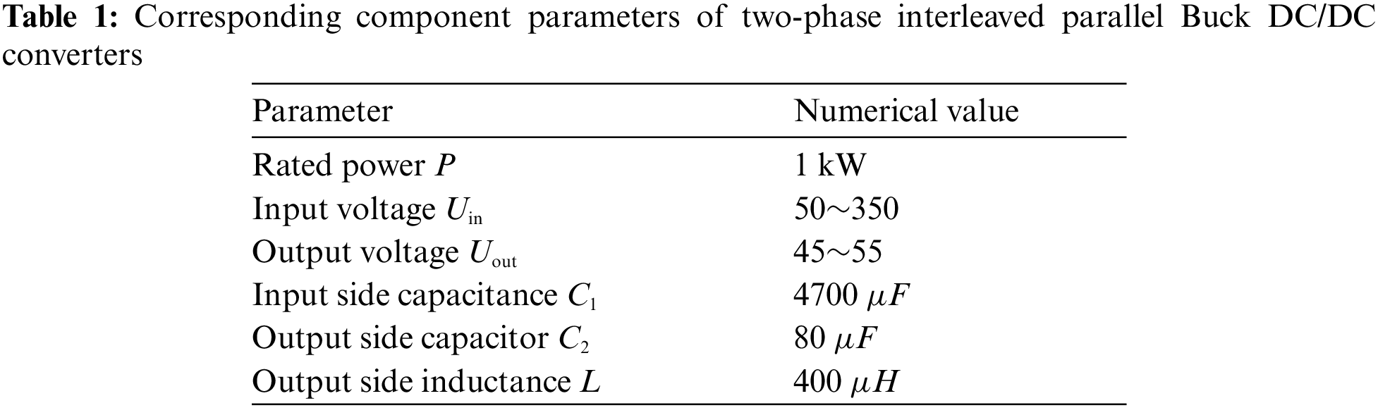
A PI controller is designed using the converter element parameters shown in Tab. 1 and the circuit parameters of the thermoelectric generator at rated power to improve the dynamic stability performance of the feedback MPPT control loop.
Transfer function of DC/DC input voltage to duty cycle
The transfer function of DC/DC input voltage to duty cycle before and after correction is shown in Fig. 6, the cut-off frequency of

Figure 6: Bode plot of

Figure 7: Corrected
3.1 Modified Conductance Incremental Method
Usually, the incremental conductance method adopts a fixed-step strategy, and the selection of the step change

Figure 8: Schematic diagram of variable step size algorithm
In order to solve the problem of the proportional coefficient
In the formula,

Figure 9: Schematic diagram of the improved variable-step conductance increment method
3.2 Adaptive Variable Step Size BP Neural Network Method
The advantage of a neural network is that it does not require an accurate mathematical model, but it can establish complex nonlinear relationships between input and output. In this paper, the feedforward BP-ANN method is adopted. There are three-layer networks. The transfer functions of the hidden layer and the output layer are tansig and purelin. The neural structure is trained by the gradient descent method. The input layer has two neurons, the hidden layer has 5 neurons, and the output layer consists of only one neuron. As shown in Fig. 10, the two input quantities are the change dV of the output voltage of the thermoelectric generator and the change dP of the output power, and the output quantity is the increase or decrease of the normalized duty cycle (±1).

Figure 10: Proposed BP neural network configuration
In order to adjust the weights, according to the gradient descent method, the formula is as follows
where
The neural network established in MATLAB is shown in Fig. 11. After 444 training iterations, the root mean square error (RMSE) can reach 6.86 × 10³.

Figure 11: Error training result
The adopted BP neural network method operates in two modes: Offline and online. Firstly, in offline mode, collect 200 sets of experimental data of the conductance incremental method with a fixed step size
When the on-board thermoelectric generator is running in a steady state, the temperature of the exhaust pipe and the output power of the thermoelectric generator do not change or change slowly. When the operating conditions of the engine suddenly change, the temperature and flow rate of the exhaust gas will change drastically, resulting in a sudden change in the output power of the thermoelectric generator. If the traditional fixed-step BP neural network method is used to find the new maximum power point, the dilemma of slow convergence speed and steady-state oscillation will occur. Because choosing a larger step size can ensure that the dynamic time is shortened, but steady-state oscillation is inevitable. Choosing a smaller step size can reduce steady-state oscillation, but it will be accompanied by the problem of poor dynamic performance. In order to account for the on-board thermoelectric generator's tracking speed and steady-state accuracy, this paper proposes an adaptive variable step size adjustment strategy according to the power variation characteristics of the on-board thermoelectric generator, as shown below.
In the formula,
In the adaptive variable step size adjustment strategy, the dimensioning factor
To sum up, a new hybrid MPPT algorithm is proposed as shown in Fig. 12.

Figure 12: Proposed control algorithm flowchart
4 Simulation and Experimental Analysis
The equivalent circuit model of a single thermoelectric module is a voltage source connected in series with a resistor, and its output is related to the temperature difference between the hot and cold ends. As shown in Fig. 13, the Simulink model of the thermoelectric generator consists of 60 thermoelectric modules (Bi2Te3) connected in series.
Set the initial temperature difference of the thermoelectric generator
The simulation results of the proposed algorithm, the separate improved conductance incremental method (SIINC) and the separate BP artificial neural network method (SBP-ANN) are shown in Figs. 14–16. Fig. 14 shows the simulation waveforms of the tracking accuracy of the three MPPT algorithms. It can be seen that when the temperature difference of the thermoelectric generator is

Figure 13: Simulink model of thermoelectric generator

Figure 14: Comparison of the MPPT tracking accuracy for the algorithms

Figure 15: Comparison of the MPPT response time of the algorithms

Figure 16: Comparison of the MPPT overshoot for the algorithms
It shows that the HM and SBP-ANN search for the maximum power is very close to the theoretical value, and the steady-state accuracy is very high. However, when SIINC tracks the maximum power, the duty cycle of the DC/DC converter changes drastically, resulting in a lot of power loss, so its steady-state accuracy is not high.
As shown in Fig. 15, when ΔT is from 0°C to 198.7°C, the response times of HM, SIINC and SBP-ANN for tracking the maximum power are 1.8 s, 0.84 s and 2 s respectively. It shows that in each switching cycle, the SIINC adopts the largest step size change, so the startup time and response time are the shortest, and the HM proposed in this paper combines the advantages of SBP-ANN and SIINC, and has good startup speed and response speed. However, the SBP-ANN collects the experimental data of the conductance increment method with a fixed step size
As shown in Fig. 16, when
In order to verify the effectiveness of the proposed HM algorithm, a test bench was created for AETEG which is depicted in Fig. 17, the car engine model is Citroen Sega 2.0 PSA RFN 10LH3X, the capacity is 1997 mL, the maximum power is 108 kW (6000 r/min), the maximum Torque 200 NM (4000 r/min). The heat conduction area of the heat energy air box is 542 mm × 280 mm, and the cooling area of the cold source water tank is also 542 mm × 280 mm. The material of the thermoelectric module is Bi2Te3, and the number is 60. The rated power of the DC/DC converter is 1 kW, and the specific parameters are shown in Tab. 1. Following the steady-state tracking test, the thermoelectric generator is directly connected to the electronic load, and the true maximum power of the thermoelectric generator is determined using the current sweep method. The thermoelectric generator is then linked to the 48 V battery through the DC/DC converter included into the MPPT algorithm. Secondly, we performed dynamic tracking experiment. At 1.6 s, the speed and torque of the car engine jump from 3000 r/min@65NM to 2600 r/min@58NM. The proposed HM algorithm and the traditional SIINC, SBP-ANN algorithms are embedded into the digital controller TMS320F28335, its PWM module outputs the drive signal to the IGBT device to realize the MPPT algorithm.

Figure 17: AETEG test bench with embedded MPPT algorithm
When the automobile engine runs in two stable conditions (3000 r/min@65NM, 2600 r/min@ 58NM), the results are shown in Tabs. 2 and 3 and Figs. 18 and 19. As shown in Fig. 18, the maximum tracking powers of HM, SIINC and SBP-ANN are 114.87 W, 110.49 W and 112.45 W in turn, and the deviation rate of the proposed algorithm is the smallest (1.53%), indicating that it’s steady-state accuracy is the highest and consistent with the simulation results. Due to the existence of actual circuit losses (switching losses of switching tubes, impedance losses of wires), the MPPT result has a certain error with the actual value.
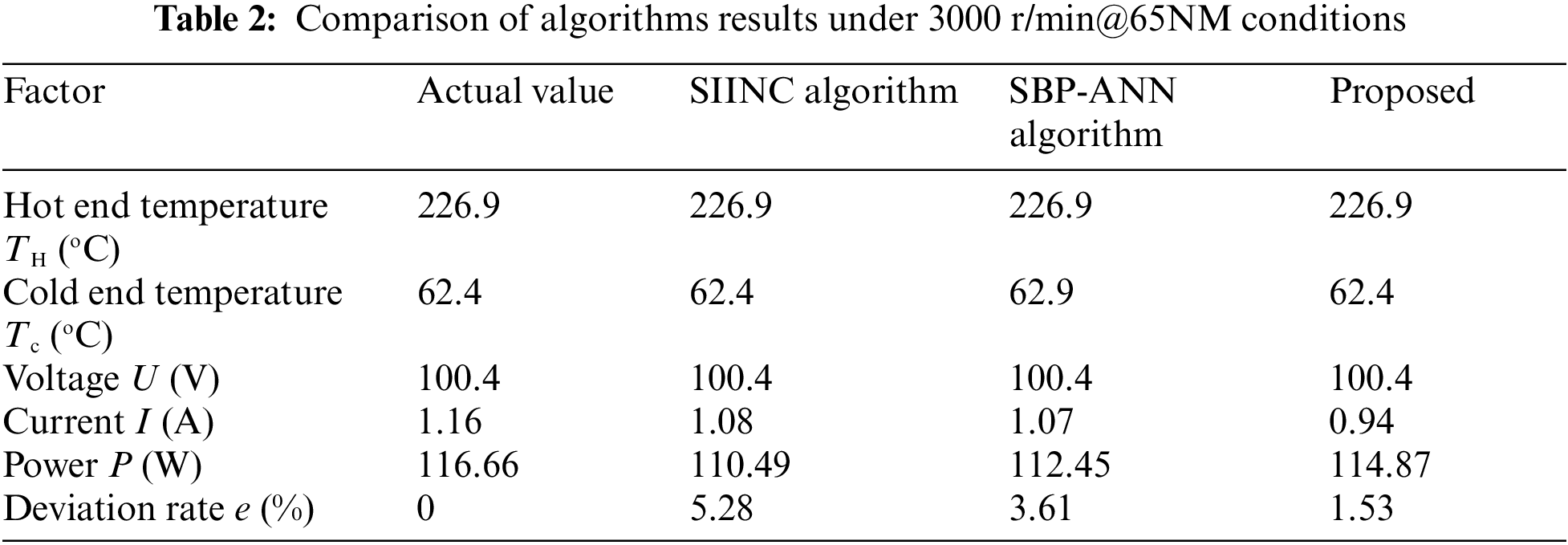
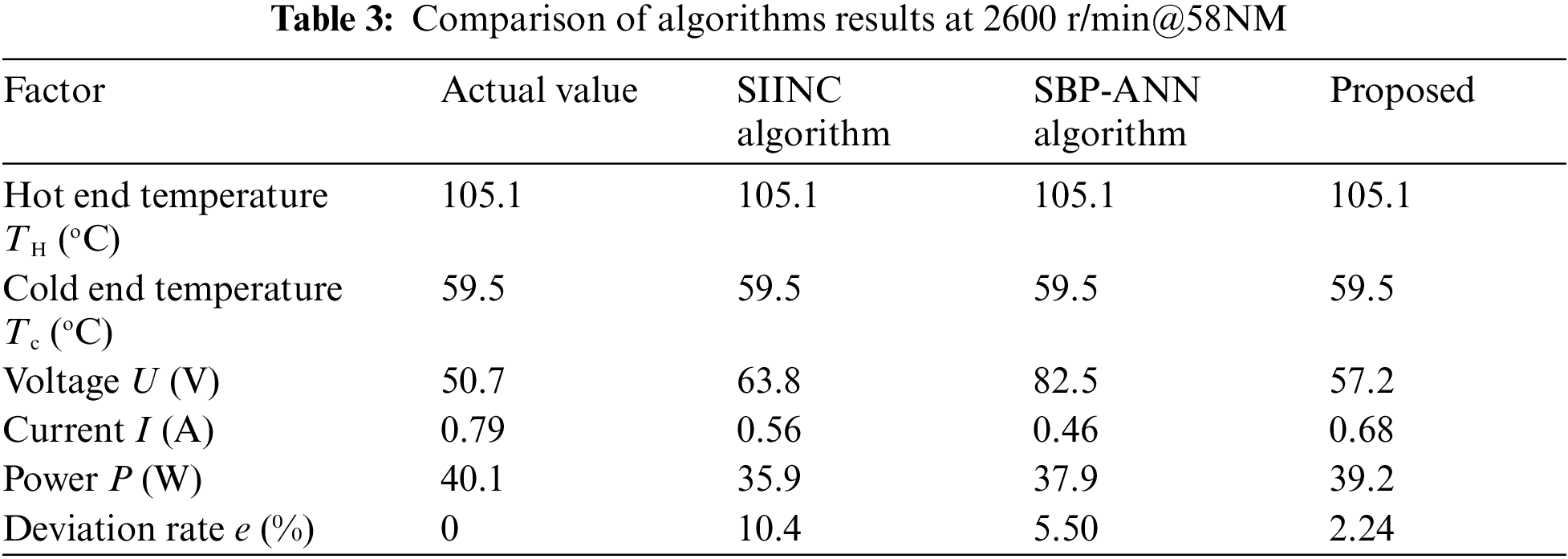

Figure 18: The actual output of AETEG and the results of different MPPT algorithms at 3000 r/min@65 NM

Figure 19: The actual output of AETEG and the results of different MPPT algorithms at 2600 r/min@58 NM
As shown in Fig. 19, the HM, SIINC and SBP-ANN algorithms find the maximum powers to be 39.2, 35.9 and 37.9 W respectively. In addition, when the engine speed and torque suddenly change from 0 to 3000r/min@65NM, the maximum power tracking start time of the proposed algorithm is 2 s, which is 0.4 s more than SIINC but 0.8 s less than the SBP-ANN algorithm, indicating that the starting speed and response speed of the suggested approach is a hybrid of SIINC and SBP-ANN, which matches the simulation findings. Since BP-ANN is used in the second stage of the proposed algorithm, its step size change is smaller than the ΔD of SIINC method, so the startup time is not as good as SIINC (See Fig. 20).

Figure 20: The results of different MPPT algorithms when the speed and torque of the car engine jumped from 3000 r/min@65 NM to 2600 r/min@58 NM
Among them, the response times of proposed, SIINC and SBP-ANN algorithms are 2.4, 2 and 3.2 s, indicating that SIINC has the shortest dynamic response time, but its overshoot of 5.9 W is greater than 2.1 W of proposed algorithm and 3.8 W of SBP-ANN algorithm, causing great damage to the circuit components of the DC/DC converter. The experimental results show that the proposed algorithm outperforms the traditional SIINC and SBP-ANN algorithms in terms of stability and dynamic performance.
This paper proposed a novel algorithm for thermoelectric generator based on neural networks.
(1) The AETEG system based on the 48 V electrical architecture is proposed, which can improve the fuel economy of the vehicle and achieve the effect of energy saving and emission reduction.
(2) The design and implementation of the double closed-loop interleaved Buck converter ensures the high efficiency and stability of the AETEG system.
(3) Based on the maximum power tracking strategy, the improved conductance increment method can be used when far from the maximum power point, which can improve the dynamic performance of the system. When approaching the maximum power point, the adaptive variable step size BP neural network method can reduce the steady-state oscillation.
(4) Simulation and experimental results show that the hybrid method proposed in this paper can not only improve the output power of the on-board thermoelectric generator, but also reduce the response time of the system.
Acknowledgement: The authors would like to thanks the editors and reviewers for their review and recommendations.
Funding Statement: The authors received no specific funding for this study.
Conflicts of Interest: The authors declare that they have no conflicts of interest to report regarding the present study.
1. S. Twaha, J. Zhu, L. Maraaba, K. Huang, B. Li et al., “Maximum power point tracking control of a thermoelectric system using the extremum seeking control method,” Energies Journal, vol. 10, no. 12, pp. 1–18, 2017. [Google Scholar]
2. S. Kim, S. Park and K. Kim, “A thermoelectric generator using engine coolant for light-duty internal combustion engine-powered vehicles,” Journal of Electronic Materials, vol. 24, no. 5, pp. 812–816, 2011. [Google Scholar]
3. H. Mamur, M. Ustuner and M. Bhuiyan, “Future perspective and current situation of maximum power point tracking methods in thermoelectric generators,” Sustainable Energy Technologies and Assessment Journal, vol. 50, no. 3, pp. 742–763, 2022. [Google Scholar]
4. T. Zhang, “New thinking on modeling of thermoelectric devices,” Applied Energy, vol. 168, no. 7, pp. 65–74, 2016. [Google Scholar]
5. W. He, W. Wang and Y. Yang, “Peak power evaluation and optimal dimension design of exhaust heat exchanger for different gas parameters in automobile thermoelectric generator,” Energy Conversion and Management, vol. 151, no. 3, pp. 661–669, 2017. [Google Scholar]
6. M. Comamala, I. Cozar, A. Massaguer, E. Massaguer and T. Puiol, “Effects of design parameters on fuel economy and output power in an automotive thermoelectric generator,” Energies Journal, vol. 11, no. 12, pp. 1–18, 2018. [Google Scholar]
7. I. Cozar, T. Puiol and M. Lehocky, “Numerical analysis of the effects of electrical and thermal configuratios of thermoelectric modules in large-scale thermoelectric generators,” Applied Energy Journal, vol. 299, no. 6, pp. 264–280, 2018. [Google Scholar]
8. A. Abdullah, H. Rezk, A. Alboye, M. Hassan and A. Mohamed, “Grey wolf optimizer-based fractional MPPT for thermoelectric generator,” Intelligent Automation & Soft Computing, vol. 29, no. 3, pp. 729–740, 2021. [Google Scholar]
9. A. Jordehi, “Maximum power point tracking in photovoltaic (PV) systems: A review of different approaches,” Renewable and Sustainable Energy Reviews, vol. 65, no. 1, pp. 1127–1138, 2016. [Google Scholar]
10. C. Li, Y. Chen, D. Zhou, J. Liu and J. Zeng, “A high-performance adaptive incremental conductance MPPT algorithm for photovoltaic systems,” Energies Journal, vol. 9, no. 4, pp. 1–16, 2016. [Google Scholar]
11. H. Islam, S. Mekhilef, N. Shah, T. Soon and M. Seyed, “Performance evaluation of maximum power point tracking approaches and photovoltaic systems,” Energies Journal, vol. 9, no. 8, pp. 1043–1063, 2015. [Google Scholar]
12. L. Elobaid, A. Abdelsalam and E. Zakzouk, “Artificial neural network-based photovoltaic maximum power point tracking techniques: A survey,” IET Renewable Power Generation, vol. 9, no. 8, pp. 1043–1063, 2015. [Google Scholar]
13. A. Dounis, P. Kofinas and G. Papadakis, “A direct adaptive neural control for maximum power point tracking of photovoltaic system,” Solar Energy, vol. 115, no. 5, pp. 145–165, 2015. [Google Scholar]
14. H. Yamada, K. Kimura and T. Hanamoto, “A novel MPPT control method of thermoelectric power generation with single sensor,” Applied Sciences, vol. 3, no. 2, pp. 545–558, 2013. [Google Scholar]
15. Z. Dalala and M. Saadeh, “A new maximum power point tracking (MPPT) algorithm for thermoelectric generators with reduced voltage sensors count control,” Energies Journal, vol. 11, no. 7, pp. 1826–1841, 2018. [Google Scholar]
16. D. Tatarinov, M. Koppers and G. Bastian, “Modeling of a thermoelectric generator for thermal energy regeneration in automobiles,” Journal of Electronic Materials, vol. 42, no. 7, pp. 2274–2281, 2013. [Google Scholar]
17. Y. Deng, S. Zheng and C. Su, “Effect of thermoelectric modules topological connection on automotive exhaust heat recovery system,” Journal of Electronic Materials, vol. 45, no. 3, pp. 1740–1750, 2016. [Google Scholar]
18. J. Gao, K. Sun and L. Ni, “A thermoelectric generation systems and its power electronics stage,” Journal of Electronic Materials, vol. 41, no. 6, pp. 1043–1050, 2012. [Google Scholar]
19. R. Tan, “Design of boost converter based on maximum power point resistance for photovoltaic applications,” Solar Energy, vol. 160, no. 7, pp. 322–335, 2018. [Google Scholar]
20. C. Jiang and H. Liu, “A novel interleaved parallel bidirectional dual-active-bridge dc-dc converter with coupled inductor for more-electric aircraft,” IEEE Transactions on Industrial Electronics, vol. 68, no. 2, pp. 1759–1768, 2021. [Google Scholar]
21. A. Osadrahimi and Y. Mahmoud, “Novel spline-MPPT technique for photovoltaic systems under uniform irradiance and partial shading conditions,” IEEE Transactions on Sustainable Energy, vol. 12, no. 1, pp. 524–532, 2020. [Google Scholar]
22. S. Messalti, A. Harrag and A. Loukriz, “A new variable step size neural networks MPPT controller: Review, simulation and hardware implementation,” Renewable and Sustainable Energy Reviews, vol. 68, no. 2, pp. 221–233, 2017. [Google Scholar]
 | This work is licensed under a Creative Commons Attribution 4.0 International License, which permits unrestricted use, distribution, and reproduction in any medium, provided the original work is properly cited. |