DOI:10.32604/cmc.2022.025636
| Computers, Materials & Continua DOI:10.32604/cmc.2022.025636 | |
| Article |
Triple-Band Metamaterial Inspired Antenna for Future Terahertz (THz) Applications
1Center for Applied Electromagnetic (EMCenter), Faculty of Electrical and Electronic Engineering, Universiti Tun Hussein Onn Malaysia (UTHM), Batu Pahat, 86400, Johor, Malaysia
2Faculty of Engineering Electrical Engineering Dep., Al Baha University, Alaqiq, 65799, Al-Baha, Saudi Arabia
3Advanced Telecommunication Research Center (ATRC), Faculty of Electrical and Electronic Engineering, Universiti Tun Hussein Onn Malaysia (UTHM), Batu Pahat, 86400, Johor, Malaysia
4Faculty of Electrical and Electronic Engineering Technology, Universiti Teknikal Malaysia Melaka, Hang Tua Jaya, 76100, Durian Tunggal, Melaka, Malaysia
5Department of Mathematics, Physics, and Electrical Engineering, Northumbria University, NE1 8ST Newcastle Upon Tyne, UK
6Department of Electronic Engineering, Dawood University of Engineering and Technology, Karachi, 74800, Pakistan
*Corresponding Author: S. H. Dahlan. Email: samsulh@uthm.edu.my
Received: 30 November 2021; Accepted: 07 January 2022
Abstract: For future healthcare in the terahertz (THz) band, a triple-band microstrip planar antenna integrated with metamaterial (MTM) based on a polyimide substrate is presented. The frequencies of operation are 500, 600, and 880 GHz. The triple-band capability is accomplished by etching metamaterial on the patch without affecting the overall antenna size. Instead of a partial ground plane, a full ground plane is used as a buffer to shield the body from back radiation emitted by the antenna. The overall dimension of the proposed antenna is 484 × 484 μm2. The antenna's performance is investigated based on different crucial factors, and excellent results are demonstrated. The gain for the frequencies 500, 600, 880 GHz is 6.41, 6.77, 10.1 dB, respectively while the efficiency for the same frequencies is 90%, 95%, 96%, respectively. Further research has been conducted by mounting the presented antenna on a single phantom layer with varying dielectric constants. The results show that the design works equally well with and without the phantom model, in contrast to a partially ground antenna, whose performance is influenced by the presence of the phantom model. As a result, the presented antenna could be helpful for future healthcare applications in the THz band.
Keywords: THz; metamaterial; triple-band; wireless body area networks (WBAN)
Terahertz (THz) technology has recently caught the interest of academicians, scientists, and researchers due to its numerous applications in communication, circular dichroism (CD) spectroscopy, radio astronomy, vehicular radar, explosive detection, planetary, health monitoring, sensing, imaging, and security, among others [1–3]. THz is defined by the International Telecommunication Union (ITU) as being in the range of 0.1–10 THz, which lies between millimeter-wave and infrared bands [4–6]. The main reason for this investigation is the THz band's main advantages, which include but are not limited to high data rate, high confidentiality, low loss, low probability of interference, compact size, high smoke dust penetrability, lower power requirements, and high resolution [7–9]. This investigation has resulted in efforts to integrate THz technology into wireless communication systems. Various antenna designs have been investigated to incorporate THz technology into wireless communication systems [1–13]. Among the antenna designs studied, microstrip planar antennas were discovered to be a very suitable candidate when compared to other designs with complex or three-dimensional designs [11,14–16]. This is due to the fact that it includes features such as high compatibility with the built-in THz system [11,14–16]. The low gain, signal frequency band, and narrow bandwidth of microstrip planar antenna designs limit their use. Introducing metamaterials (MTMs) is one approach to overcoming these issues.
In today's communications world, antennas that operate at multiple frequencies play an important role in meeting the ever-changing needs of miniaturized communications equipment. Most communication devices on the market have the smallest space for integrating antennas. To provide enhanced and multifunctional performance, they require antennas to operate on multiple operating frequency bands based on their applications [17,18]. The pre-specified requirements resulted in developing a single antenna capable of operating in multiple frequency bands simultaneously. Cost-effectiveness and size are the important benefits of multi-band antennas, which are attained with the help of microstrip patch antennas. The conventional single-band antenna can increase the number of antenna elements in multi-band wireless communication systems. Hence, it cannot meet the needs of modern communications. For this reason, multi-band antennas are introduced and rapidly become a research hot spot. Several methods have been described at low frequencies to obtain multi-band antenna, such as parasitic elements, stacked patch, microstrip feed line, different slots cut in a patch, defected ground structure (DGS), and fractal structures [17,18].
Concerning the above multi-band antenna realizing approaches, MTMs have attracted the attention of scientists, academicians, and researchers due to their unusual electromagnetic properties. MTMs are any material designed to have characteristics not possessed by natural materials and are produced artificially. They are commonly arranged in a repetitive pattern, the scale of which is smaller than the wavelength of the phenomenon they affect. Their arrangement, direction, size, geometry, and precise shape, give them the intelligent characteristics of manipulating electromagnetic waves: by bending waves, enhancing, absorbing, or blocking to attain advantages beyond the possibilities of traditional materials. They also can exhibit negative permeability along with negative permittivity [19–22]. These features enable researchers and scientist to explore MTMs in several applications at the THz regime such as absorber [23], sensor [19,24], biosensor [25,26], biomedical sensing [27], filter [28], resonator [21], reflector [9,29], health monitoring [30,31]. MTMs have also been reported to improve the antennas performance [3,22,32–35].
In this paper, a triple-band microstrip planar antenna integrated with metamaterial (MTM) is presented. The operating frequencies are 500, 600, and 880 GHz. By etching the MTM on the microstrip planar antenna, a triple-band antenna is achieved due to the MTM features that are not available in nature. The triple bands are wider than the bandwidths of single microstrip planar antenna. The design is simple that can be easily fabricated. The antenna has a size of 484 × 484 × 25 μm3. To the best of the author's knowledge, only single band microstrip planar antenna at THz frequency spectrum is available yet. Furthermore, the presented antenna integrated with MTM achieves stable performance such as efficiency, gain, and radiation pattern over the triple frequency bands. It also studied while loaded on a single phantom model and shows performance equal to the case without the phantom model.
The presented microstrip planar antenna is developed on a polyimide substrate with permittivity of 3.4 and a thickness of 25 μm. This substrate was chosen because it has better broadband performance, radiation efficiency, and gain than other substrates [11]. On the other side of the substrate, a full ground plane was selected for better radiation, efficiency, and gain performance. In addition, the full ground plane is preferred in antenna designs that tend to be used in healthcare applications [36]. Besides, it isolates the antenna from the body and reduces the impact on the performance of the antenna when the user places it on the human body. The microstrip planar antenna was excited by 50 Ω microstrip line. The ground plane, radiating patch, and feedline were constructed from graphene material. The graphene has an ohmic surface of 0.3 and a thickness of 0.1 μm. The optimized presented microstrip planar antenna has an overall size of 484 × 484 μm2. The initial stage of the developed microstrip planar antenna starts based on a rectangular patch with a size of 318 × 236 μm2, as depicted in Fig. 1.
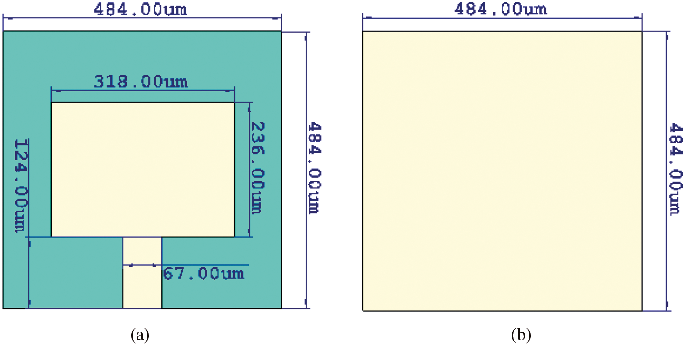
Figure 1: Conventional rectangular antenna in CST (a) front view, (b) back view
The performance of the final optimized microstrip planar antenna model was studied using CST Microwave Studio based on the Time Domain. The result revealed that the antenna is operating at 479 GHz, and it has a reflection coefficient of less than −26 dB. The reflection coefficient is plotted in Fig. 2. The result shows that the conventional rectangular microstrip antenna operates only on a single frequency band. However, the single band antenna is not suitable for applications running on multiple frequency bands because developers need to use multiple antennas to meet the requirement of these applications. Therefore, this article introduces a triple-band antenna that operates in the THz bands, complying with the systems requiring triple operating frequencies. The triple bands were obtained without modifying the antenna size. It is achieved by using the advantages of the MTM characteristics.
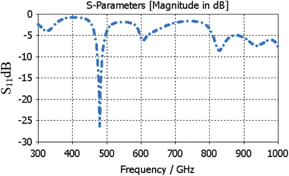
Figure 2: S11 of conventional rectangular microstrip antenna
3 Metamaterial Unit Cell Design
The MTM unit cell is built on the same substrate and the same conducting materials as the antenna. It consists of a square patch shaped and circular slot. The unit cell has a dimension of 140 × 140 × 25 μm3. The numerical simulation of the unit cell was performed using the finite integration technique (FIT) in CST Microwave Studio based on a frequency-domain solver. The presented MTM structure is situated between two waveguide ports along the ±z-axis. Boundary conditions are applied with a perfect magnetic conductor (PMC) and a perfect electric conductor (PEC) along the x-axis and y-axis, respectively, to characterize the effective MTM parameters as depicted in Fig. 3.
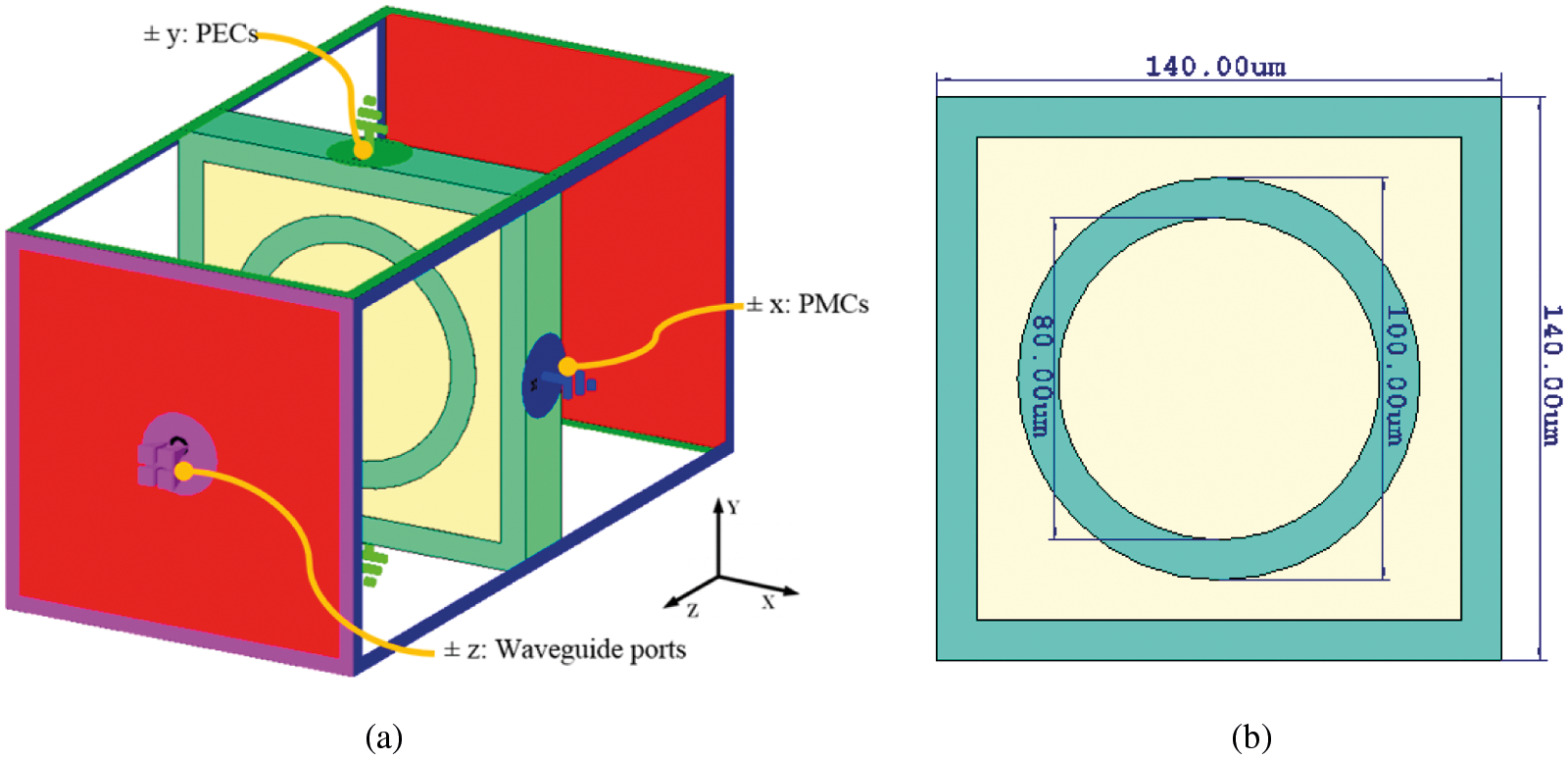
Figure 3: (a) 3D perspective setup of the MTM unit cell in CST microwave studio, (b) front view
As shown in Fig. 4, the simulated S-parameters of the MTM unit cell, such as transmission coefficient and reflection coefficient, are investigated. The unit cell has a stopband frequency resonating at 566 GHz, according to the results. The stopband below −10 dB covers the frequency band from 502 to 616 GHz. S-parameters were used to calculate the design characteristics such as permeability, permittivity, and refractive index (n). The Robust Retrieval Method based on MATLAB software [37] and the built-in CST post-processing technique [38] used to calculate the unique characteristics. The effective parameters were calculated using Eq. (1) through (4).
where the logarithmic part of Eq. (2),
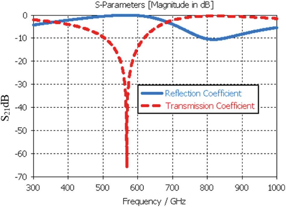
Figure 4: Transmission and reflection coefficients of the presented MTM unit cell
The extraction of results based on the MATLAB software and built-in CST post-processing technique is compared. It realized that both gave similar results. Therefore, the extracted result in this paper is based on the built-in CST post-processing technique due to its friendly use and less time-consuming. The results of the real and imaginary parts of effective parameters are plotted in Fig. 5. The results reveal that the real value of permittivity and refractive index have negative values at the frequency band range from 526 to 775 GHz, and 567 to 727 GHz, respectively. Furthermore, the real permeability shows a positive value. This type of MTM can be graded as single negatives (SNG) left-handed (LH), which is classified as an epsilon negative (ENG) MTM. These feature does not exist in nature, but it is based on the engineered design.
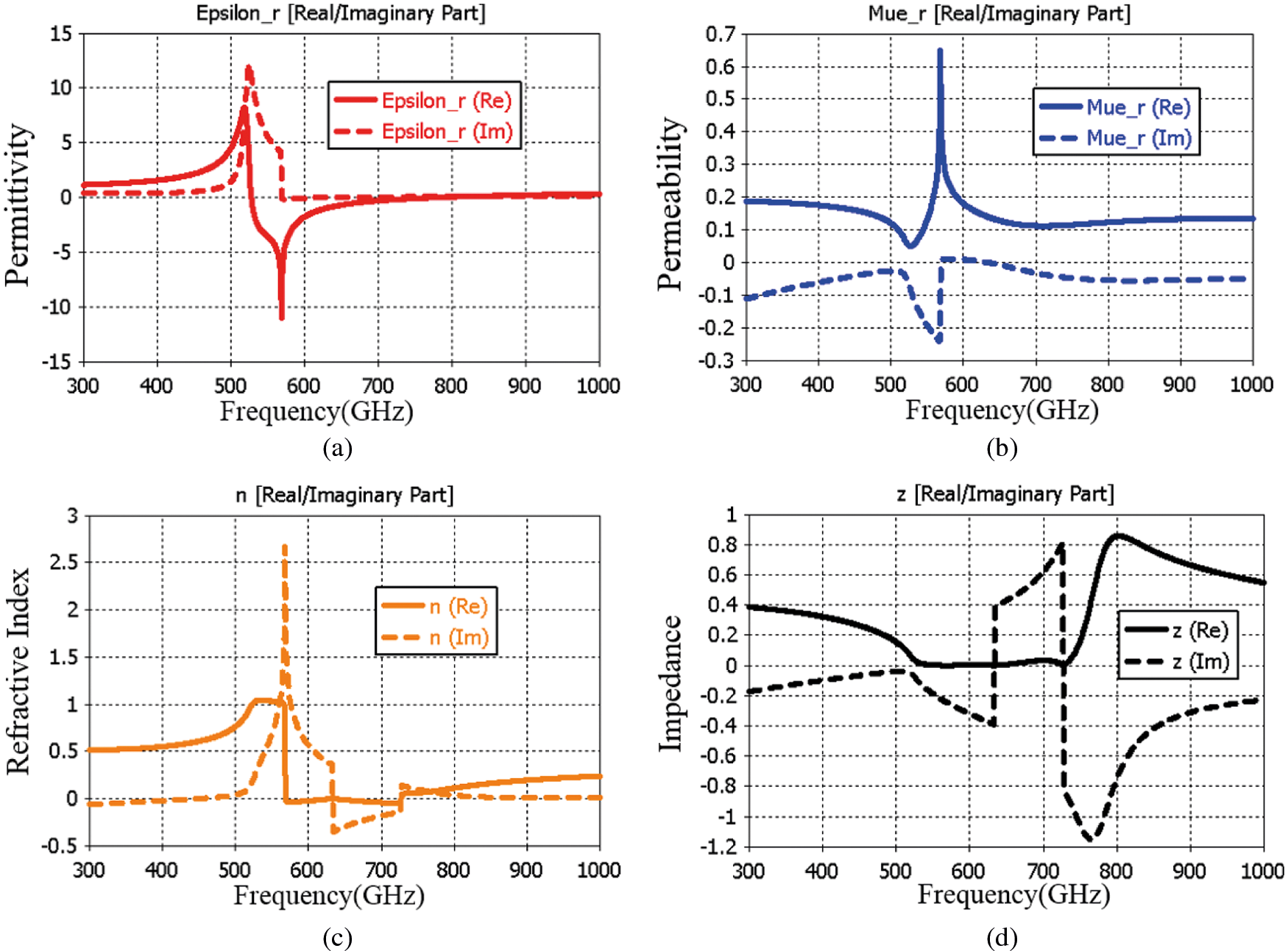
Figure 5: Effective medium parameters of the MTM unit cell and (a) permittivity, (b) permeability, (c) refractive index, and (d) impedance
Parametric studies were carried out to study the impact of width, outer and inner on the characteristics of the MTM unit cell, such as the real permittivity and refractive index at the THz band. The width of the patch was changed from 55 to 65 μm with an increment step of 5 μm, whereas other parameters were kept unchanged as in Fig. 3. The real permittivity and refractive index with different patch widths are plotted in Fig. 6. It is easily observed that when the width is increased, real permittivity and refractive index decrease progressively. The observation shows that the relationship between the width and the characteristics of the MTM is inversely proportional. Furthermore, the outer of the circular slot was varied from 45 to 55 μm while the inner was varied from 35 to 45 μm, whereas, other parametric kept unchanged as in Fig. 3. The results are illustrated in Fig. 7. It can be seen that the variation of the outer and inner have the same influence as that of the patch width is attained.
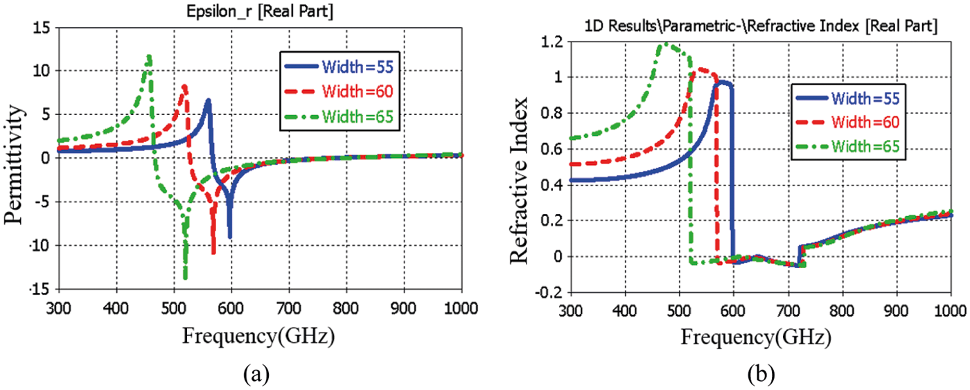
Figure 6: Study the effects of varying the width on the (a) permittivity and, (b) refractive index
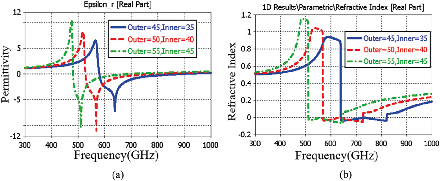
Figure 7: Study the effects of varying the outer and inner on the (a) permittivity and, (b) refractive index
Triple-band antenna is preferred over a single band antenna for applications requiring more than one band due to its cost-effectiveness, reliability, and miniaturization. Furthermore, a triple-band antenna has a much smaller footprint than three separate antennas at the required frequencies to meet the application demands.
MTMs have been used to improve antenna performance in several THz band antenna designs. The proposed MTM demonstrated that the integration with the antenna could create a triple band without modifying the antenna dimensions. This is because its epsilon negative (ENG) cannot be found in nature. It is discovered, however, based on shape, geometry, dimension, orientation, and arrangement. Electromagnetic waves can cause them to react differently. The MTM structure is etched on the top of the antenna, as shown in Fig. 8. The reflection coefficient, S11 of the antenna after etching MTM is plotted in Fig. 9. With the addition of the MTM, the planar antenna exhibits triple frequency bands. The operating frequencies are 500, 600, and 880 GHz, respectively, with reflection coefficients of −23, −47, and −32 dB. Furthermore, triple frequency bands of 488 to 510 GHz, 586 to 615 GHz, and 856 to 942 GHz are realized.
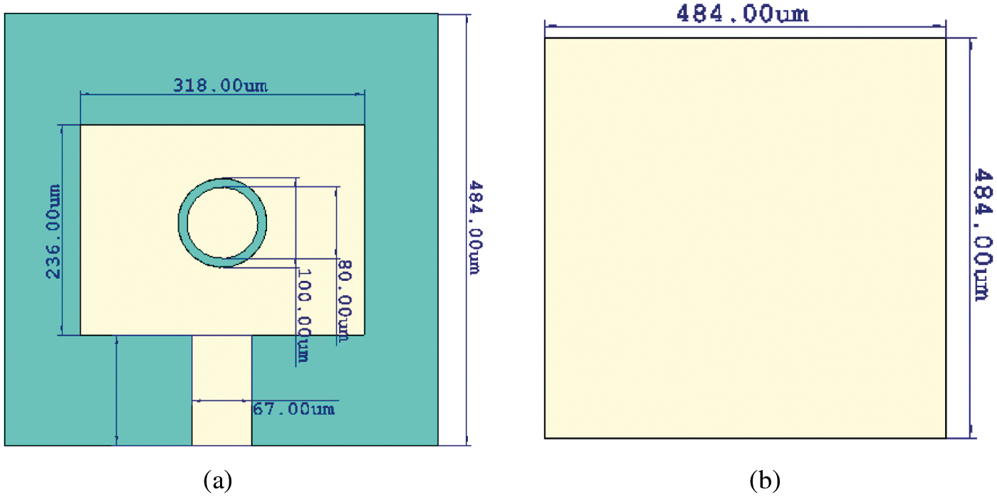
Figure 8: Integrate antenna with MTM (a) front view, (b) back view
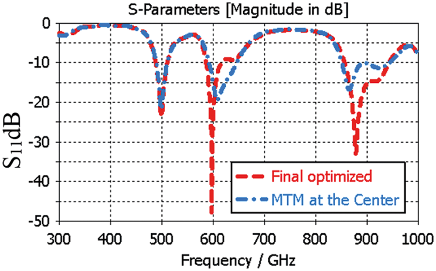
Figure 9: Reflection coefficient of the adding MTM to the antenna
The simulated current distributions on etching the MTM on the radiating patch at 500, 600, and 880 GHz are depicted in Fig. 10 to examine the triple-band antenna approach better. According to Fig. 10a, when the integrated antenna with MTM operates at 500 GHz, the current is uniformly distributed across the patch, and the resonant mode of the lower frequency band is excited. The current focus is partially on etching the MTM unit cell at 600 GHz, as shown in Fig. 10b, and completely on etching the MTM unit at 880 GHz, as shown in Fig. 10c. Overall, it is clear that the etching of the MTM unit on the patch is the main cause of the resonating frequencies at 600 and 880 GHz.
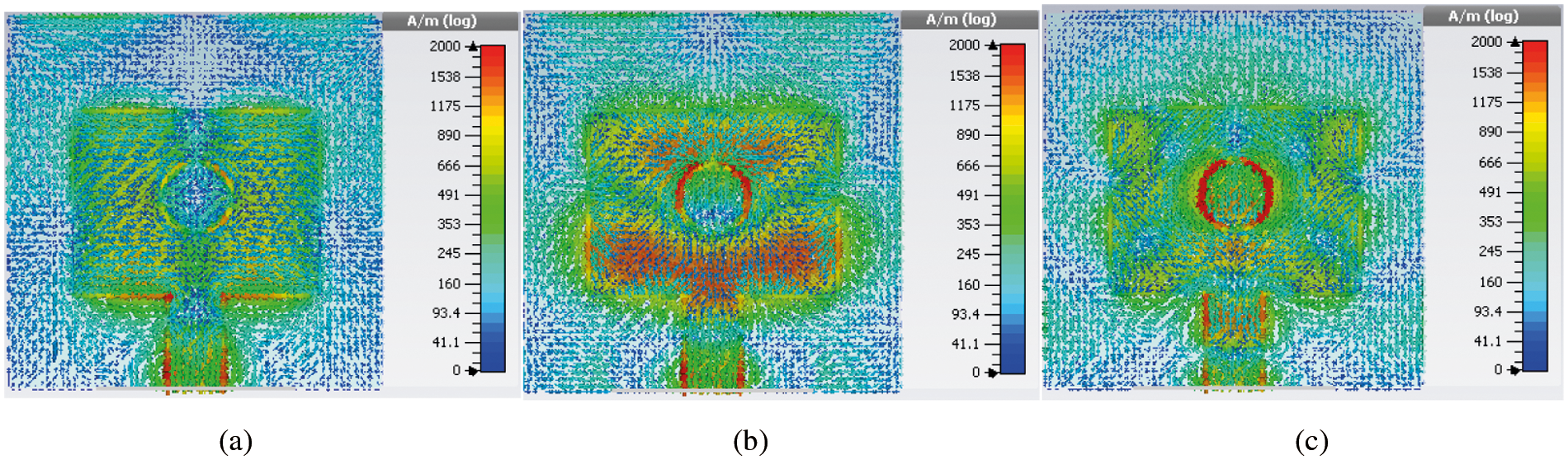
Figure 10: The simulated surface current distributions of the MTM antenna (a) at 500 GHz; (b) at 600 GHz; (c) at 880 GHz
The position of the MTM was selected based on a parametric study. Initially, it was placed at the center of the conventional rectangular patch. Then, it moves along the ±x-axis and ±y-axis. The results are plotted in Fig. 11. It can be seen that the best performance was obtained when the unit cell was moved along the +y-axis. The final optimized unit cell is moved along the +y-axis with 7.5 μm.
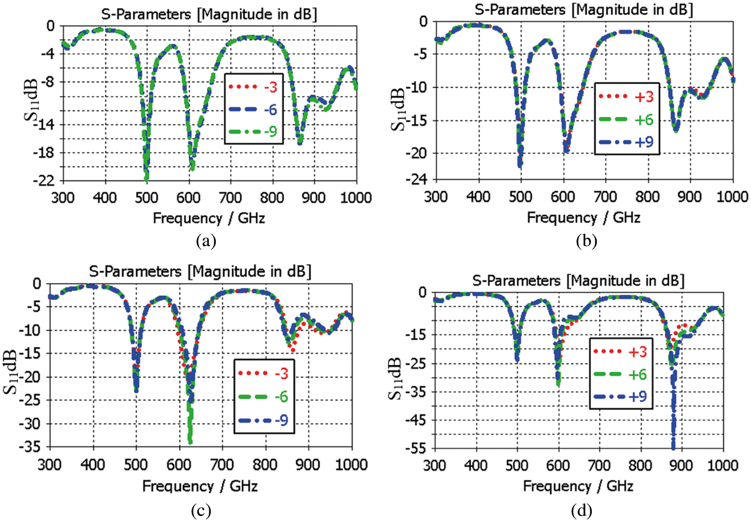
Figure 11: Position of the MTM (a) the unit cell moved along −x-axis, (b) the unit cell moved along +x-axis, (c) the unit cell moved along −y-axis, (d) the unit cell moved along the +y-axis
Figs. 12 and 13 show the simulated radiation pattern of the signal band with the full ground and triple-band antennas along the E-plane and H-plane, respectively. The E-plane and H-plane of the single band and triple-band can be seen to be comparable. This is due to the full ground, which reflects most of the energy from the back to the front. In addition, the gain of both antennas is investigated. At 480 GHz, the single band antenna with the full ground has a gain of 5.95 dB and a radiation efficiency of 90%. On the other hand, the triple-band antenna gains 6.41 dB at 500 GHz, 6.77 dB at 600 GHz, and 10.1 dB at 880 GHz, while the radiation efficiency is 91%, 95%, and 96%, respectively. The results show that the MTM not only contributes to creating triple bands but also improves the gain and radiation efficiency compared to conventional patches.
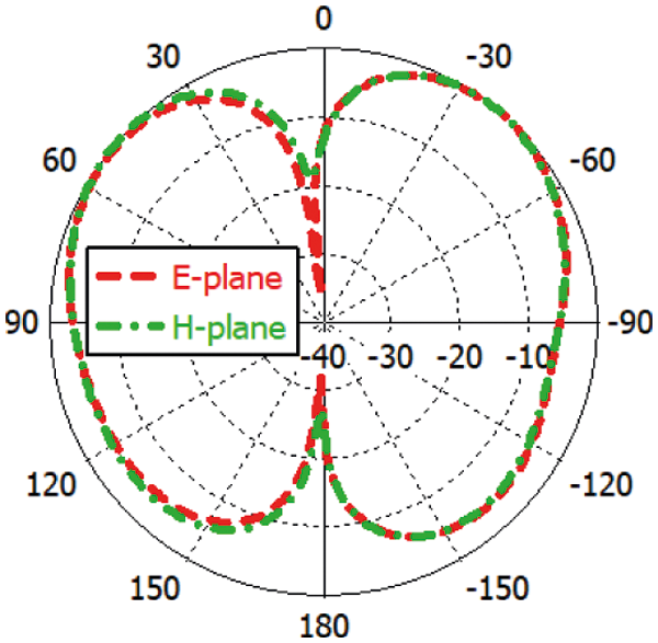
Figure 12: Radiation of the antenna without MTM (single band)
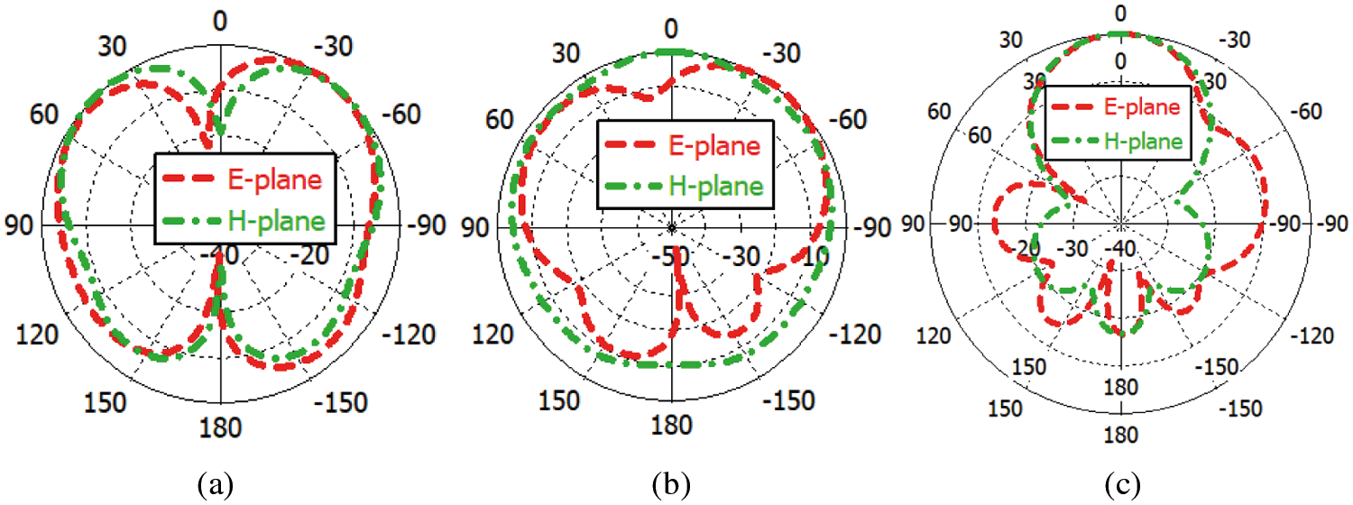
Figure 13: Radiation of the integrated antenna with MTM (a) 500 GHz, (b) 600 GHz, and (c) 880 GHz
THz band has become an important technology of the future because of its spatial properties. It also received more and more attention due to its wide application in the fields of technology and science, including biology, physics, strong light-matter coupling, non-destructive sensing, and imaging, information, and communications technology (ICT), and other fields.
THz has appealing medical applications due to its numerous unique features, such as low photon energy, better contrast for soft tissues, no harmful ionization of biological tissue precise measurements, limited penetration into the body, and ability to differentiate between different materials or even isomers [3,34]. These characteristics have caught the interest of researchers working on wireless body area networks (WBAN) under this regime. WBAN is primarily used for health monitoring and consists of actuators and sensors placed beneath or on the human skin [39,40]. It can also be used in entertainment, sports, and other areas. Antennas are a component of the sensor that aid in data transmission to the terminal location. As a result, the antenna is considered an essential component of the WBAN.
As the antenna will be deployed on the human chest, therefore, its performance will be hampered due to the body's high conductivity. Furthermore, in WBAN, the specific absorption rate (SAR) is an important parameter to consider. It is the primary determinant of electromagnetic wave absorption by human tissues.
Several THz antennas have been designed for WBAN, but they are based on partial ground DGS [4–13], which are not suitable for WBAN applications because the human body influences them. Furthermore, these designs anticipate high back radiation, which is expected to be hazardous to one's health.
As the presented integrated antenna with MTM is for future health care application, the impact of the tissue on the design is essential to study. The study ensures that the antenna is operating equally, either in free space or on tissue. It also to see the impact of tissues on the antenna at THz frequencies. A single layer of tissue is developed to carry out the study with a size of 700 × 700 × 100 μm3 as shown in Fig. 14. The permittivity of the tissue was varied with several values 15, 45, 65, and 135. These values were chosen to consider several scenarios that may have different values of permittivity. It also ensures that the proposed design can comply even if loaded on tissue with high permittivity. The presented design is loaded directly on the skin, which is the worst case with a high effect on the antenna performance compared to when there is a gap between the tissue and the antenna model. Fig. 15 illustrates the result of the presented antenna on the single-layer tissue. It can be observed that the S11 of the antenna loaded on the tissue with different permittivity values has a good agreement with the S11 of the antenna without tissue. This is due to the presence of the full ground plane that acts as shielding between the antenna and body.
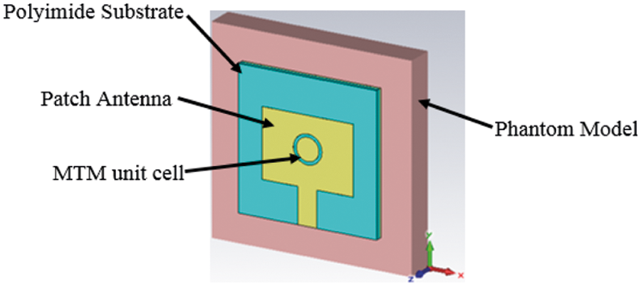
Figure 14: Performance of the antenna integrated MTM on a phantom with various permittivity
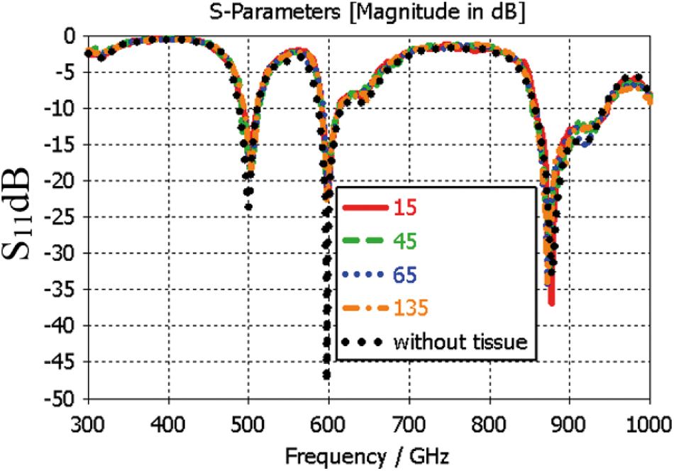
Figure 15: Performance of the antenna integrated MTM on a phantom with various permittivity
A signal band antenna with a partial ground is designed to show the usefulness of the presented antenna integrated with MTM, as shown in Fig. 16. The aim is to show the benefits of using a full ground plane in antenna design that tends to be used for WBAN applications.
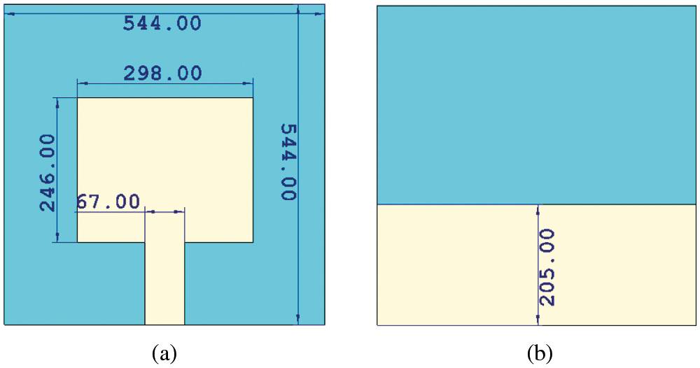
Figure 16: Microstrip antenna based on partial ground (a) front view, (b) back view
Fig. 17 depicts the performance of a single partial ground antenna. It demonstrates that the S11 has a large number of harmonics that can interfere with other systems. The result indicates that when the antenna performance analysis is performed without using a phantom model, the antenna operates at 540 GHz. When the antenna is loaded onto the phantom model, the antenna performance suffers. According to theory, adding a high permittivity object to the antenna will cause the antenna to shift to a lower frequency; thus, the antenna's operating frequency while loading on the phantom model could be 420 GHz. This is due to the partial ground plane, which caused the phantom model to act as a new complex layer of substrate, causing mounting the antenna directly on the body to result in a dramatic mismatch in antenna performance, as shown in Fig. 17.
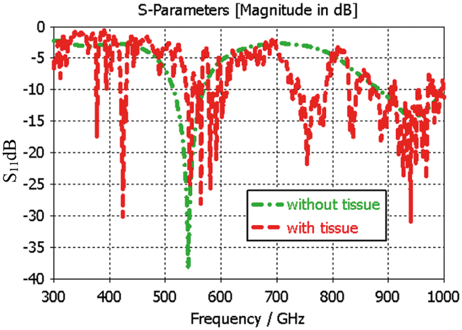
Figure 17: Performance of the partial ground antenna on phantom
Further investigation is being conducted to compare the performance of the presented antenna with MTM with ground plane and the single band antenna with the partial ground in terms of the radiation pattern, efficiency, and gain.
Fig. 18 depicts the radiation pattern of a single band antenna with the partial ground and with and without a phantom Fig. 18a. The results showed that the antenna has high back radiation in the absence of the phantom model, which is undesirable for on-body applications that may pose health risks. When the phantom model is used, the back radiation is reduced, indicating that the phantom observed some amount of power, which is not highly recommended due to health concerns such as impaired blood circulation and tissue damage. This is due to the human body's ability to act as an extension of the ground plane; thus, placing the single band antenna with the partial ground on the phantom model resulted in significant disparities in the antenna's results. Furthermore, as shown in Figs. 18b and 18c, the gain and efficiency of both cases are compared. It is discovered that in the absence of the phantom model, the gain is 7.3 dB and the efficiency is 92%, whereas, in the presence of the phantom, the gain and efficiency are 2.65 dB and 38.7%, respectively. This is due to the phantom model's high permittivity, which degraded the antenna's performance.
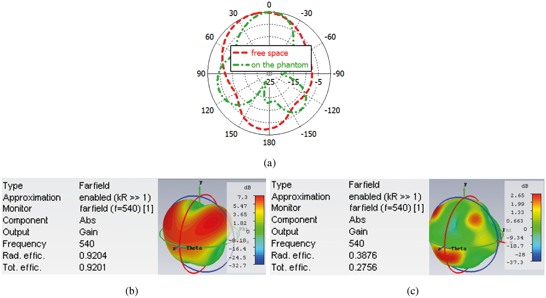
Figure 18: Fairfield result of the partial ground antenna (a) radiation pattern on phantom and free space, (b) gain and efficiency in free space, and (c) gain and efficiency on phantom
The antenna's radiation pattern, on the other hand, is carried out using a MTM with the full ground plane. The outcomes are depicted in Fig. 19. It can be seen that the radiation pattern is comparable with and without the phantom model. This indicates that there is no power will be observed by the body which is demanded for WBAN applications. Furthermore, the gain and efficiency for the case with and without phantom are calculated, as illustrated in Figs. 20 and 21. The gain without the phantom model is 6.41, 6.77, and 10.1 dB for frequencies 500, 600, and 880 GHz, respectively, while the efficiency is 90%, 95%, and 96% for the same frequencies.
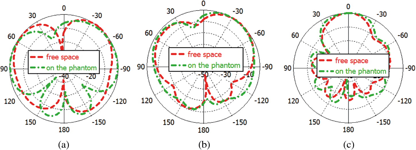
Figure 19: Radiation pattern of the antenna with MTM on phantom and free space (a) 500 GHz, (b) 600 GHz, and (c) 880 GHz
Furthermore, the gain and efficiency for the case with a phantom for the frequencies 500, 600, and 8800 GHz are 5.88, 5.44, and 10.1 dB, respectively, while the efficiency for the same frequencies is 89%, 91%, and 95%. There is a minor difference in the frequencies 500 and 600 GHz results, but it is not statistically significant. The presented antenna with MTM has significant advantages in terms of achieving high-level stability results. This is due to the presence of a full ground plane, which acts as a shield between the antenna and the body.
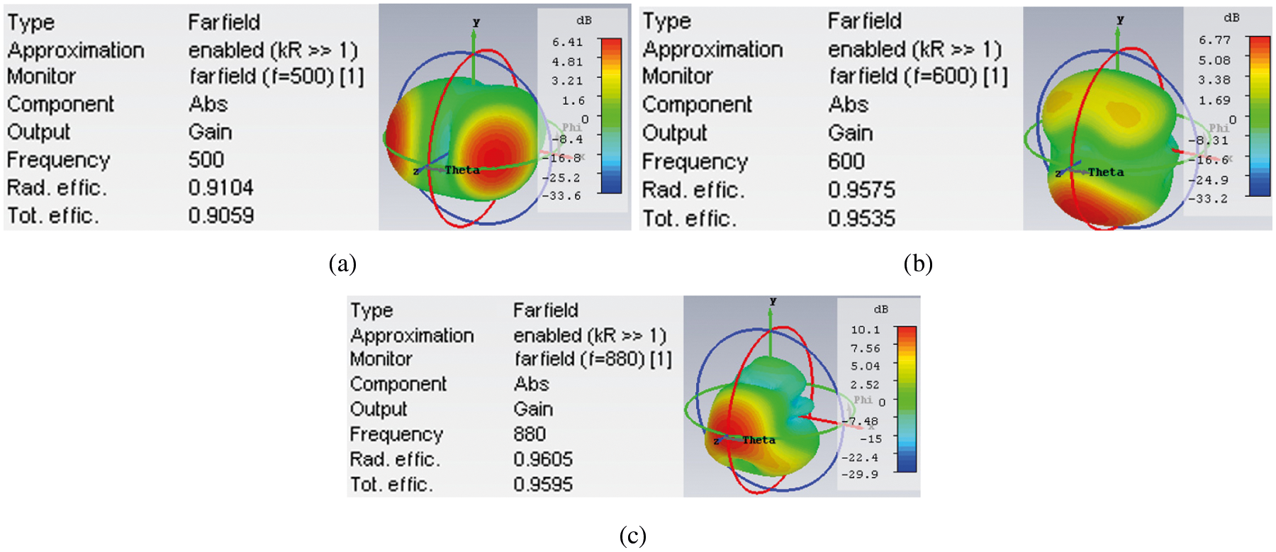
Figure 20: Gain and efficiency of the antenna with MTM in free space (a) 500 GHz, (b) 600 GHz, and (c) 880 GHz
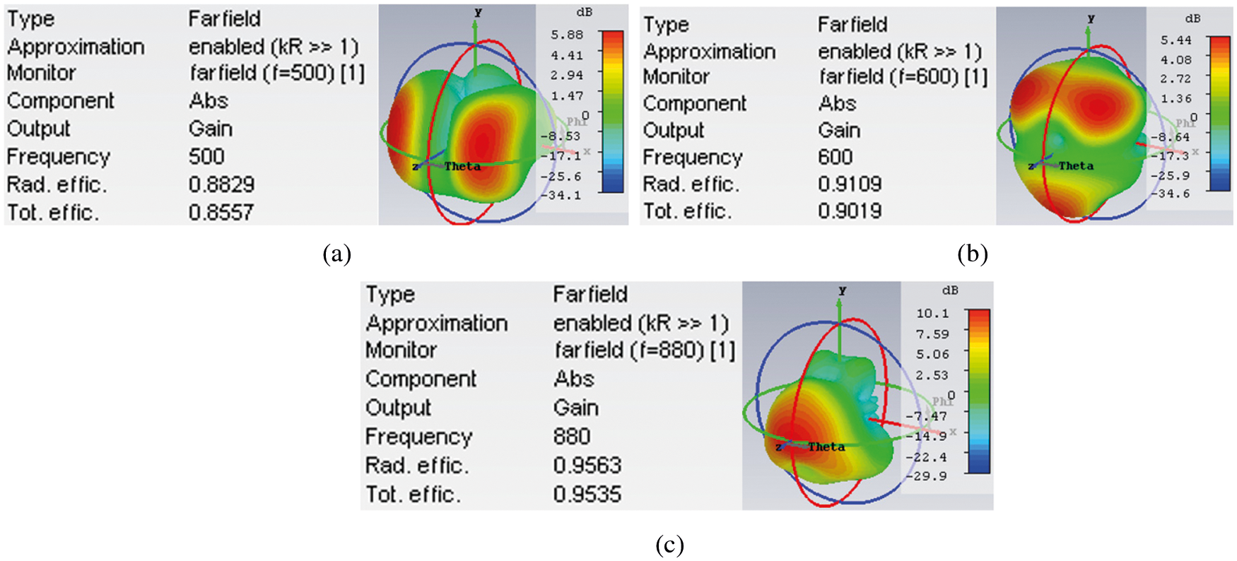
Figure 21: Gain and efficiency of the antenna with MTM on phantom (a) 500 GHz, (b) 600 GHz, and (c) 880 GHz
A triple-band microstrip planar antenna integrated with MTM based on a polyimide substrate is presented in the THz band for future healthcare applications. The design is simple and can be easily manufactured and integrated for THz systems. The antenna initially operated in a single frequency band of 480 GHz, while when the MTM was etched on the patch, the antenna achieved a triple-band of 500, 600, and 880 GHz. The triple-band was achieved without changing the overall size of the antenna. Parametric studies were carried out to investigate the influence of width, outer and inner on the characteristics of the MTM such as the real permittivity and refractive index at the THz band. A parametric study was also conducted to select the best etching position on the patch. The performance of the presented antenna was evaluated. The gain for the frequencies 500, 600, 880 GHz is 6.41, 6.77, 10.1 dB, respectively while the efficiency for the same frequencies is 90%, 95%, 96%, respectively. Further studies are carried out to evaluate the design performance when loaded on a single phantom layer. The results show that the design can work equally with and without the use of the phantom model. In addition, a partially grounded antenna was introduced. The goal is to demonstrate the utility of the presented antenna integrated with MTM. The placement of the phantom model impacted the performance of the partial ground antenna. This is because the phantom model appears as an additional layer with a high dielectric constant to the antenna. As a result, it is not recommended that partially grounded antennas be used in future healthcare THz band applications. Unlike the presented antenna, which is based on the full ground and is suitable for future healthcare applications in the THz band.
Funding Statement: The authors received no specific funding for this study.
Conflicts of Interest: The authors declare that they have no conflicts of interest to report regarding the present study.
1. A. Singh, M. Andrello, N. Thawdar and J. M. Jornet, “Design and operation of a graphene-based plasmonic nano-antenna array for communication in the terahertz band,” IEEE Journal on Selected Areas in Communications, vol. 38, no. 9, pp. 2104–2117, 2020. [Google Scholar]
2. S. Thakur and N. Singh, “Circular-slot thz antenna on pbg substrate for cancer detection,” Optik (Stuttg), vol. 242, no. June, pp. 167355, 2021. [Google Scholar]
3. I. E. Carranza, J. Grant, J. Gough and D. R. S. Cumming, “Metamaterial-based terahertz imaging,” IEEE Transactions on Terahertz Science and Technology, vol. 5, no. 6, pp. 892–901, 2015. [Google Scholar]
4. U. Keshwala, S. Rawat and K. Ray, “Design and analysis of eight petal flower shaped fractal antenna for thz applications,” Optik (Stuttg), vol. 241, no. April, pp. 166942, 2021. [Google Scholar]
5. S. Singhal, “Asymmetrically cpw fed square sierpinski carpet ultra wideband terahertz antenna,” Optik (Stuttg), vol. 242, no. April, pp. 167056, 2021. [Google Scholar]
6. V. Das and S. Rawat, “Modified rectangular planar antenna with stubs and defected ground structure for thz applications,” Optik (Stuttg), vol. 242, no. April, pp. 167292, 2021. [Google Scholar]
7. S. Singhal, “Cpw fed jasmine shaped superwideband terahertz antenna for pattern diversity applications,” Optik (Stuttg), vol. 231, no. December 2020, pp. 166356, 2021. [Google Scholar]
8. U. Keshwala, S. Rawat and K. Ray, “Design and analysis of dna shaped antenna for terahertz and sub-terahertz applications,” Optik (Stuttg), vol. 232, no. February, pp. 166512, 2021. [Google Scholar]
9. R. K. Kushwaha, P. Karuppanan and N. Kishore, “High-gain patch antenna design using prs and ground plane reflector for thz band applications,” Optik (Stuttg), vol. 232, no. February, pp. 166559, 2021. [Google Scholar]
10. U. Keshwala, S. Rawat and K. Ray, “Inverted k-shaped antenna with partial ground for thz applications,” Optik (Stuttg), vol. 219, no. April, pp. 165092, 2020. [Google Scholar]
11. S. Das, D. Mitra and S. R. Bhadra Chaudhuri, “Fractal loaded circular patch antenna for super wide band operation in thz frequency region,” Optik (Stuttg), vol. 226, no. P2, pp. 165528, 2021. [Google Scholar]
12. U. Keshwala, S. Rawat and K. Ray, “Plant shaped antenna with trigonometric half sine tapered leaves for thz applications,” Optik (Stuttg), vol. 223, no. September, pp. 165648, 2020. [Google Scholar]
13. U. Keshwala, K. Ray and S. Rawat, “Ultra-wideband mushroom shaped half-sinusoidal antenna for thz applications,” Optik (Stuttg), vol. 228, no. November 2020, pp. 166156, 2021. [Google Scholar]
14. T. Li, B. Ma, X. Du, H. Y. Chen, R. C. Deng et al., “A novel design of microstrip patch antenna array with modified-i-shaped electromagnetic metamaterials applied in microwave wireless power transmission,” Optik (Stuttg), vol. 173, no. 95786, pp. 193–205, 2018. [Google Scholar]
15. S. Singhal, “Cpw fed koch snowflake superwideband terahertz spatial diversity antenna,” Optik (Stuttg), vol. 206, no. January, pp. 164329, 2020. [Google Scholar]
16. M. N. eddine Temmar, A. Hocini, D. Khedrouche and T. A. Denidni, “Enhanced flexible terahertz microstrip antenna based on modified silicon-air photonic crystal,” Optik (Stuttg), vol. 217, no. May, pp. 164897, 2020. [Google Scholar]
17. P. B. Nayak, S. Verma and P. Kumar, “A novel compact tri-band antenna design for wimax, wlan and bluetooth applications,” in 2014 Twentieth National Conf. on Communications (NCC), Kanpur, India, pp. 1–6, 2014. [Google Scholar]
18. P. J. C. Sam and N. Gunavathi, “A tri-band monopole antenna loaded with circular electric–inductive–capacitive metamaterial resonator for wireless application,” Applied Physics A, vol. 126, no. 10, pp. 774, 2020. [Google Scholar]
19. A. S. Saadeldin, M. F. O. Hameed, E. M. A. Elkaramany and S. S. A. Obayya, “Highly sensitive terahertz metamaterial sensor,” IEEE Sensors Journal, vol. 19, no. 18, pp. 1, 2019. [Google Scholar]
20. M. H. Jyothi, D. V. Bipin, B. Choudhury and R. U. Nair, “Design of conformal metamaterial unit cells for invisibility cloaking applications,” in 2016 IEEE Annual India Conf. (INDICON), Bangalore, India, pp. 1–5, 2016. [Google Scholar]
21. W. Wang,Y. Hou, F. Yan, S. Tan, H. Li et al., “Symmetry breaking and resonances hybridization in vertical split ring resonator metamaterials and the excellent sensing potential,” Journal of Lightwave Technology, vol. 37, no. 19, pp. 5149–5157, 2019. [Google Scholar]
22. R. Jie, H. Jing, S. Li and Y. Xiao, “Dual-band circular polarizers based on a planar chiral metamaterial structure,” IEEE Antennas and Wireless Propagation Letters, vol. 18, no. 12, pp. 2587–2591, 2019. [Google Scholar]
23. D. B. Stojanovic, G. Gligoric, P. P. Belicev, M. R. Belic and L. Hadzievski, “Circular polarization selective metamaterial absorber in terahertz frequency range,” IEEE Journal of Selected Topics in Quantum Electronics, vol. 27, no. 1, pp. 1–6, 2021. [Google Scholar]
24. P. Cao, Y. Wu, Z. Wang, Y. Li, J. Zhang et al., “Tunable dual-band ultrasensitive stereo metamaterial terahertz sensor,” IEEE Access, vol. 8, pp. 219525–219533, 2020. [Google Scholar]
25. X. Hou, X. Chen, T. Li, Y. Li, Z. Tian et al., “Highly sensitive terahertz metamaterial biosensor for bovine serum albumin (bsa) detection,” Optical Materials Express, vol. 11, no. 7, pp. 2268, 2021. [Google Scholar]
26. R. Zhang, Q. Chen, K. Liu, Z. Chen, K. Li et al., “Terahertz microfluidic metamaterial biosensor for sensitive detection of small-volume liquid samples,” IEEE Transactions on Terahertz Science and Technology, vol. 9, no. 2, pp. 209–214, 2019. [Google Scholar]
27. I. Al-Naib, “Biomedical sensing with conductively coupled terahertz metamaterial resonators,” IEEE Journal of Selected Topics in Quantum Electronics, vol. 23, no. 4, pp. 1–5, 2017. [Google Scholar]
28. Z. Zhu, X. Zhang, J. Gu, R. Singh, Z. Tian et al., “A Metamaterial-based terahertz low-pass filter with low insertion loss and sharp rejection,” IEEE Transactions on Terahertz Science and Technology, vol. 3, no. 6, pp. 832–837, 2013. [Google Scholar]
29. A. Keshavarz and Z. Vafapour, “Sensing avian influenza viruses using terahertz metamaterial reflector,” IEEE Sensors Journal, vol. 19, no. 13, pp. 5161–5166, 2019. [Google Scholar]
30. J. P. Pavia, M. A. Ribeiro, C. K. Sarikaya, D. Akbar, H. Altan et al., “Design of a novel thz sensor for structural health monitoring applications,” in 2019 IEEE 20th Wireless and Microwave Technology Conf. (WAMICON), Cocoa Beach, FL, USA, pp. 1–5, 2019. [Google Scholar]
31. B. Ozbey, E. Unal, H. Ertugrul, O. Kurc, C. M. Puttlitz et al., “Wireless displacement sensing enabled by metamaterial probes for remote structural health monitoring,” Sensors, vol. 14, no. 1, pp. 1691–1704, 2014. [Google Scholar]
32. H. Jiang, M. L. Si, W. Hu and X. Lv, “A symmetrical dual-beam bowtie antenna with gain enhancement using metamaterial for 5g mimo applications,” IEEE Photonics Journal, vol. 11, no. 1, pp. 1–9, 2019. [Google Scholar]
33. Z. Liu, X. Li, J. Yin and Z. Hong, “Asymmetric all silicon micro-antenna array for high angle beam bending in terahertz band,” IEEE Photonics Journal, vol. 11, no. 2, pp. 1–9, 2019. [Google Scholar]
34. M. Zhao, S. Zhu, J. Chen, X. Chen and A. Zhang, “Broadband metamaterial aperture antenna for coincidence imaging in terahertz band,” IEEE Access, vol. 8, pp. 121311–121318, 2020. [Google Scholar]
35. W. Cao, B. Zhang, J. Jin, W. Zhong and W. Hong, “Microstrip antenna with electrically large property based on metamaterial inclusions,” IEEE Transactions on Antennas and Propagation, vol. 65, no. 6, pp. 2899–2905, 2017. [Google Scholar]
36. A. Y. I. Ashyap, Z. Z. Abidin, S. H. Dahlan, S. M. Shah, H. A. Majid et al., “A wearable antenna based on fabric materials with circular polarization for body-centric wireless communications,” Indonesian Journal of Electrical Engineering and Computer Science, vol. 18, no. 1, pp. 335, 2020. [Google Scholar]
37. X. Chen, T. M. Grzegorczyk, B. I. Wu, J. Pacheco and J. A. Kong, “Robust method to retrieve the constitutive effective parameters of metamaterials,” Physical Review E, vol. 70, no. 1, pp. 016608, 2004. [Google Scholar]
38. CST Microwave Studio, 2020. [Online]. Available: http://www.cst.com. [Accessed: 10-Oct-2016]. [Google Scholar]
39. S. Fajr, A. Rajawat and S. H. Gupta, “Design and optimization of thz antenna for onbody wban applications,” Optik (Stuttg), vol. 223, no. September, pp. 165563, 2020. [Google Scholar]
40. T. Khajawal, Q. Rubani, A. Rajawat and S. H. Gupta, “Performance analysis and optimization of band gap of terahertz antenna for wban applications,” Optik (Stuttg), vol. 243, no. June, pp. 167387, 2021. [Google Scholar]
 | This work is licensed under a Creative Commons Attribution 4.0 International License, which permits unrestricted use, distribution, and reproduction in any medium, provided the original work is properly cited. |