DOI:10.32604/cmc.2022.023993
| Computers, Materials & Continua DOI:10.32604/cmc.2022.023993 | |
| Article |
Data Hiding in AMBTC Images Using Selective XOR Hiding Scheme
1Department Electronic and Computer Engineering, National Taiwan U. Science and Technology, Taipei, 106, Taiwan
2Department Computer Science and Information Management, Providence University, Taichung, 433, Taiwan
3Grad. Inst. Automation Technology, National Taipei University of Technology, Taipei, 106, Taiwan
*Corresponding Author: Yung-Yao Chen. Email: yungyaochen@mail.ntust.edu.tw
Received: 29 September 2021; Accepted: 22 November 2021
Abstract: Nowadays since the Internet is ubiquitous, the frequency of data transfer through the public network is increasing. Hiding secure data in these transmitted data has emerged broad security issue, such as authentication and copyright protection. On the other hand, considering the transmission efficiency issue, image transmission usually involves image compression in Internet-based applications. To address both issues, this paper presents a data hiding scheme for the image compression method called absolute moment block truncation coding (AMBTC). First, an image is divided into non-overlapping blocks through AMBTC compression, the blocks are classified four types, namely smooth, semi-smooth, semi-complex, and complex. The secret data are embedded into the smooth blocks by using a simple replacement strategy. The proposed method respectively embeds nine bits (and five bits) of secret data into the bitmap of the semi-smooth blocks (and semi-complex blocks) through the exclusive-or (XOR) operation. The secret data are embedded into the complex blocks by using a hidden function. After the embedding phase, the direct binary search (DBS) method is performed to improve the image quality without damaging the secret data. The experimental results demonstrate that the proposed method yields higher quality and hiding capacity than other reference methods.
Keywords: Content protection technology; security for image data; absolute moment block truncation coding (AMBTC); direct binary search (DBS)
With the development of network technology, accessing large amounts of information from the Internet is easy. However, due to the insecure nature of the Internet, network information can be easily intercepted, leading to the illegal use of information, such as illegal downloading, forgery, and so on. Therefore, data protection has emerged as a topic of discussion. Data hiding technology can be used to protect data while maintaining message transmission.
As shown in Fig. 1, by hiding the information to be transmitted in an image and combining the relevant information of data hiding in the form of a secret key, information security is realized. Even if the image is leaked, the hidden information can only be decrypted using the secret key. However, as the volume of data hidden in the image increases, image distortion becomes obvious. If image is discovered and deciphered by outsiders, the possibility of data being extracted remains very high. Therefore, AI-based optimization algorithms are used to improve the quality of the data-embedded image (hereafter referred as the stego image). This breakthrough approach can improve the applications of data hiding.
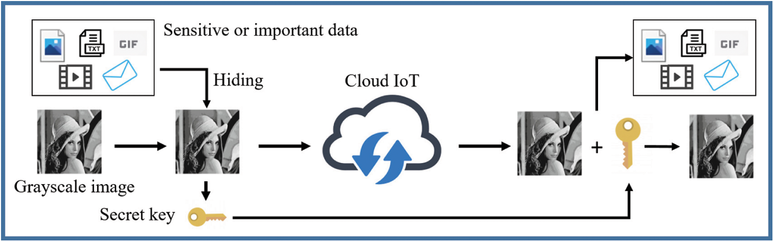
Figure 1: Application scenario of the proposed method. In the era of Internet of Things (IoT), massive data are transmitted through the Internet; among them, images are one of the commonest data. Therefore, secure image transmission becomes an essential issue. By using the proposed method, the hidden information can be embedded into the image before transmitting through the network to enhance security
Because existing data hiding schemes are often based on compression formats, we choose to hide data in a specific compression format called absolute moment block truncation coding (AMBTC) [1], which requires less calculation and delivers acceptable image quality. Therefore, it is suitable for use on computing devices with limited power, such as portable computing devices. Recently, numerous researches pertaining to the use of AMBTC technology with data hiding have been proposed. Most of them can be classified into two types: reversible data hiding (RDH) and irreversible data hiding (IDH) schemes. An image subjected to an RDH scheme can be restored in its entirety after the hiding process. Therefore, for hiding data with a high level of detail, RDH schemes are typically used. However, RDH schemes reduce the amount of secret data or require additional storage space to store the information necessary for recovery.
Recently, most RDH schemes have been based on multi-quantization [2–6] and Hamming codes [7–11]. The original AMBTC compression scheme has two quantization levels and a 16-bit bitmap. In the case of multi-quantization methods, the number of quantization levels and the number of bits in the bitmap after are higher, meaning that a greater amount of secret data can be embedded and the image quality can be improved. With these methods [2–4], AMBTC compression has been extended to four quantization levels and a 32-bit bitmap for data hiding. Zheng et al. [5] proposed an adjustable RDH method to embed two secret bits into each of the two quantization levels, resulting in eight quantization levels. Chen et al. [6] presented an adaptive RDH scheme to embed three secret bits into each of the two quantization levels, resulting in 16 quantization levels which is the same size as the original grayscale image.
The (7,4) Hamming code embeds three secret bits into seven bits while requiring only one of the seven bits to be modified, and the modified bit can be restored. Recently, numerous data hiding methods involving Hamming code have been developed. These methods [7,8] embed six bits of secret data into the bitmap by using the (7,4) Hamming code, but two bits are not used in each bitmap. In the method proposed by Lin et al. [9], the bitmap format is modified to 4 × 7 to conform to the Hamming code format for data hiding. Kim et al. [10] classified 27 situations of a seven-bit stream by following the rules of the Hamming code and generated a lookup table. In this approach, the secret data are embedded into two quantization levels. Li et al. [11] modified the Hamming code into a (3, 2) format, where two bits are embedded in the lowest three bits of two quantization levels, respectively.
For IDH schemes, least significant bit (LSB), exploiting modification directions (EMD), and pixel value difference (PVD) algorithms are the three representative methods. The LSB method embeds binary data into an image by replacing the least significant bit with the hidden data. Thus, it can hide data while maintaining the smallest difference of quantitative level as well as image quality. The PVD method hides fixed-size data by changing the difference between paired pixel values and dividing the difference into several intervals. Thus, the pixel value is not changed severely to maintain the image quality. The EMD method forms a block of n pixel values and uses three different cases to realize +1 movement, no movement, or −1 movement in one of the pixel values. By modifying only one pixel value, 2n + 1 bits can be embedded in the block. Although the IDH schemes cannot restore the original image, they typically have larger hiding capacity than the RDH schemes.
In this paper, we propose an IDH scheme, where a lookup table is used to speed up the efficiency. Utilizing lookup table is a common strategy in data hiding. For example, Zheng et al. [12] proposed using a lookup table to define one-to-many mapping between the used and unused bitmaps to hide the data. Hui et al. [13] sorted out the differences between quantity levels, and encoded the differences by Huffman coding to modify low quantity levels according to a lookup table and the secret data. Yeh et al. [14] statistically analyzed the composition of the secret data stream and developed a lookup table, which contains unique encoding and decoding dictionary search, to adjust pixel values.
In addition, the data hiding processes inevitably leads to image distortion, which increases the chance of hidden data being suspected. Therefore, researchers have employed image optimization strategies which improve image quality without damaging the hidden data. Ou et al. [15] and Hong et al. [16] adopted quantization-level modification to improve the quantization level. Mathews et al. [17] used k-means clustering to divide pixels into three sets of quantization levels in a complex block and then compress them. In this paper, the direct binary search (DBS) method was modified for image optimization. Originally, DBS is widely used to in halftoning, where it utilizes the human visual system (HVS) to continuously correct the mean square error between a continuous-tone image and the corresponding halftone image. Based on the DBS framework, we adopt the swap operator to improve the quality of a stego image.
2 Introduction to AMBTC Compression
AMBTC is a lossy image compression method. In this method, a grayscale image is first divided into non-overlapping blocks with size of n × n, and the default block size is n = 4. To compress an image block, the average value M is first calculated using Eq. (1):
where xi represents the value of the ith pixel in the block. In addition, the two quantization levels, high mean (HM) and low mean (LM), are calculated as follows:
where q represents the number of pixels in the block with values smaller than M.
The 4 × 4 bitmap is generated by comparing M with the pixel values in the block. When the pixel value is less than M, the position of the bitmap value is set to 0; otherwise, it is set to 1, resulting in the generation of the ith bitmap BMi. In this manner, a block uses two quantization levels (16 bits) and a bitmap (16 bits) to represent the trio code (HMi, LMi, BMi) of AMBTC compression. That is, after each block is compressed separately, it is represented by two quantization levels and a bitmap.
3.1 Determination of Block Type
In the AMBTC compression process, a grayscale image is divided into 4 × 4 non-overlapping blocks. In the data hiding stage, to maximize the embedding capacity in a more flexible manner, the proposed method divides the blocks into four types for which different data hiding strategies are applied. First, three thresholds T1, T2, and T3 are defined, where T1 < T2 < T3. Based on a comparison between the absolute errors of the quantization levels of each AMBTC compression block and the three thresholds, the blocks are classified as smooth, semi-smooth, semi-complex, or complex.
In the smooth block, if HM
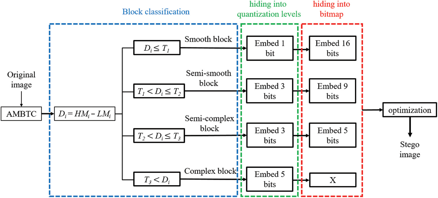
Figure 2: Overall framework of the proposed data hiding scheme
The thresholds (T1, T2, and T3) of the partition represent key information for decoding (i.e., data extraction). This information determines whether the secret data can be extracted from the stego image. Therefore, this information is saved into a secret key so that the receiver can perform decoding. The test image Lena (Fig. 3) is used as an example to illustrate the proposed block classification scheme.
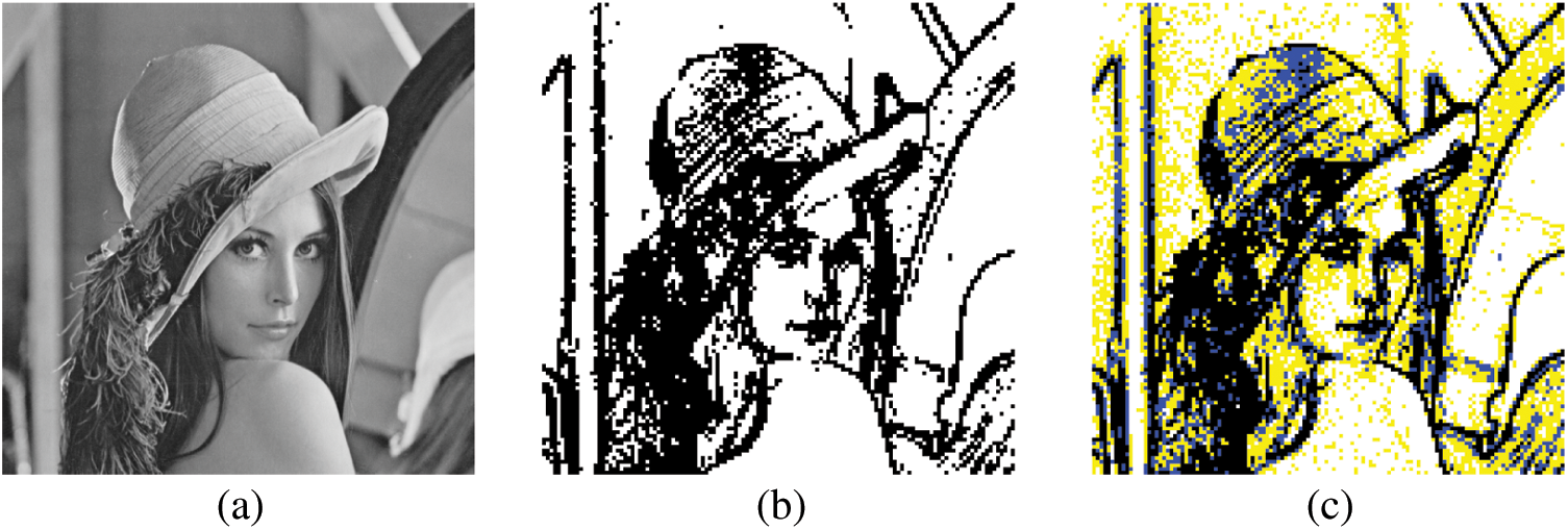
Figure 3: Illustration of the block classification. (a) Grayscale Lena image (with size of 512 × 512). (b) After AMBTC, block classification result by threshold (T = 10), where the smooth blocks are in white and the complex blocks are in black. (c) After AMBTC, block classification result by the thresholds (T1 = 5, T2 = 10, T3 = 15), where the smooth blocks are white, the semi-smooth blocks are yellow, the semi-complex blocks are blue, and the complex blocks are black. In this example, each block is with size of 4 × 4
3.2 Proposed Selective XOR Hiding Scheme
When the difference Di between the high and low quantification levels of a block represents a semi-smooth block (i.e., T1 < Di
Before describing the selective XOR hiding scheme, we must first introduce the basic structure of the scheme and the two actions to be performed. As shown in Fig. 4, in the basic architecture, a 1 × N bits is named the Nth layer. A large N value represents the upper layer, whereas a small N value represents the lower layer. Because each block is with a 4 × 4 bitmap, the uppermost layer is a 1 × 16 bits (i.e., the 16th layer), which comes from the reshaping of the bitmap. The bottom layer depends on the amount of secret data. Movement between layers is achieved by executing the actions of moving down [Eq. (4)] and moving up [Eq. (5)].
As shown in Fig. 5, to move from the Nth layer to the (N − 1)th layer (i.e., to move from an upper layer to a lower layer), we can use Eq. (4) to make the two adjacent seats of the Nth layer perform a side-by-side XOR operation to produce a row of a length of N − 1 on the (N − 1)th layer. This action is regarded as moving down, which is implemented in the data extraction stage:
where N represents the number of layers as well as the number of bits in a layer and i denotes the number of seats. Therefore,
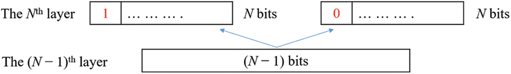
Figure 4: Illustration of the selective XOR hiding scheme: When moving from the lower layer to the upper layer, that is, when pushing up from the (N − 1)th layer to the Nth layer, the first position of the Nth layer needs to be defined as 1 or 0. By using Eq. (5), we can push back the Nth layer from the (N − 1)th layer
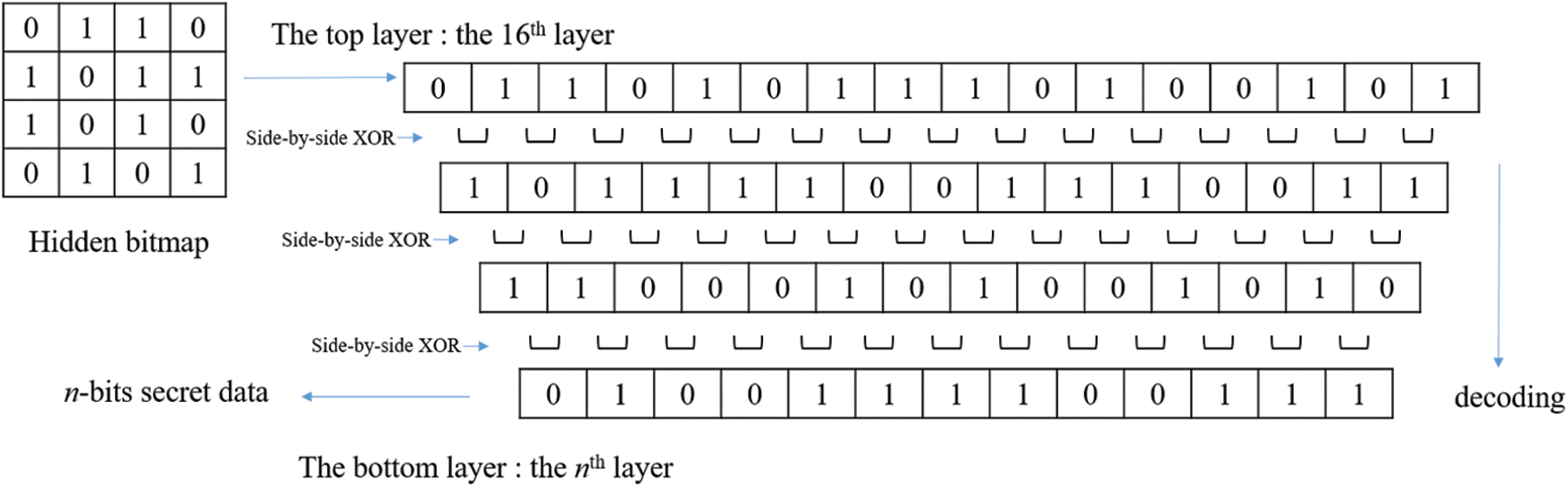
Figure 5: Data extraction diagram: After converting the hidden bitmap from the 4 × 4 configuration to the 1 × 16 configuration, the layer of secret data can be extracted by using Eq. (4) to push back from an upper layer to a lower layer
To move from the (N − 1)th layer to the Nth layer, we cannot rely solely on the information of the (N − 1)th layer. To generate the entire Nth layer, we must know the value of a seat in the Nth layer and the information of the entire (N − 1)th layer. The underlying principle is that according to the position of each row, the position can only be 1 or 0; therefore, there will be a total of 2N − 1 situations in the (N − 1)th layer and 2N situations in the Nth layer; that is, each situation belonging to the (N − 1)th layer corresponds to two situations belonging to the Nth layer, which represents a one-to-many relationship. Therefore, the two situations of the Nth layer must be first defined, and certain positions must be defined as 1 and 0. In this way, the push back calculation can be performed.
Therefore, we define the first position of the Nth layer as 1 or 0. Moreover, by using Eq. (5), the two cases of the Nth layer can be regressed from the (N − 1)th layer. This action is regarded as moving up, which is implemented in the data embedding stage.
Through the aforementioned content we create a multi-layer structure: The top layer is set to have 16 bits, and considering the n-bit secret data to be embedded, the bottom layer is set to have n bits. Starting from nth layer and pushing it up to the 16th layer, the number of layers in the middle depends on the difference between the number of secret data and 16. Finally, the 16th layer produces 216−n situations. Thereafter, all of the situations obtained from the 16th layer are converted from the 1 × 16 configuration to the 4 × 4 configuration. Therefore, the candidate bitmap patterns are generated. The candidate bitmap patterns are compared to the original grayscale block according to the mean square error (MSE) [Eq. (6)], and the optimal situation is selected to replace the original bitmap, which completes the data hiding process.
where BS represents the bitmap size, In represents the pixel value of the grayscale image block, and Pn is the pixel value of the candidate block.
Fig. 6 illustrates an example in which we embed 13 bits. Before embedding the data, we start from the 13th layer and push up to the 16th layer according to Eq. (5) to find the 8 (i.e., 216−13) possibilities of the 16th layer. Based on the corresponding situations of the 13-bit secret data and the candidate bitmaps of the 16th layer, a lookup table is constructed. When data are hidden, the 16-bit candidate bitmaps corresponding to the secret data are identified directly by using the lookup table. After the configuration is converted from 1 × 16 to 4 × 4, 0 is replaced with a low quantification level, 1 is replaced with a high quantification level, and the candidate blocks are generated. The candidate blocks are compared with the original grayscale block in terms of the MSE [Eq. (6)], and the optimal situation is selected to replace the original bitmap. This completes the data hiding process.
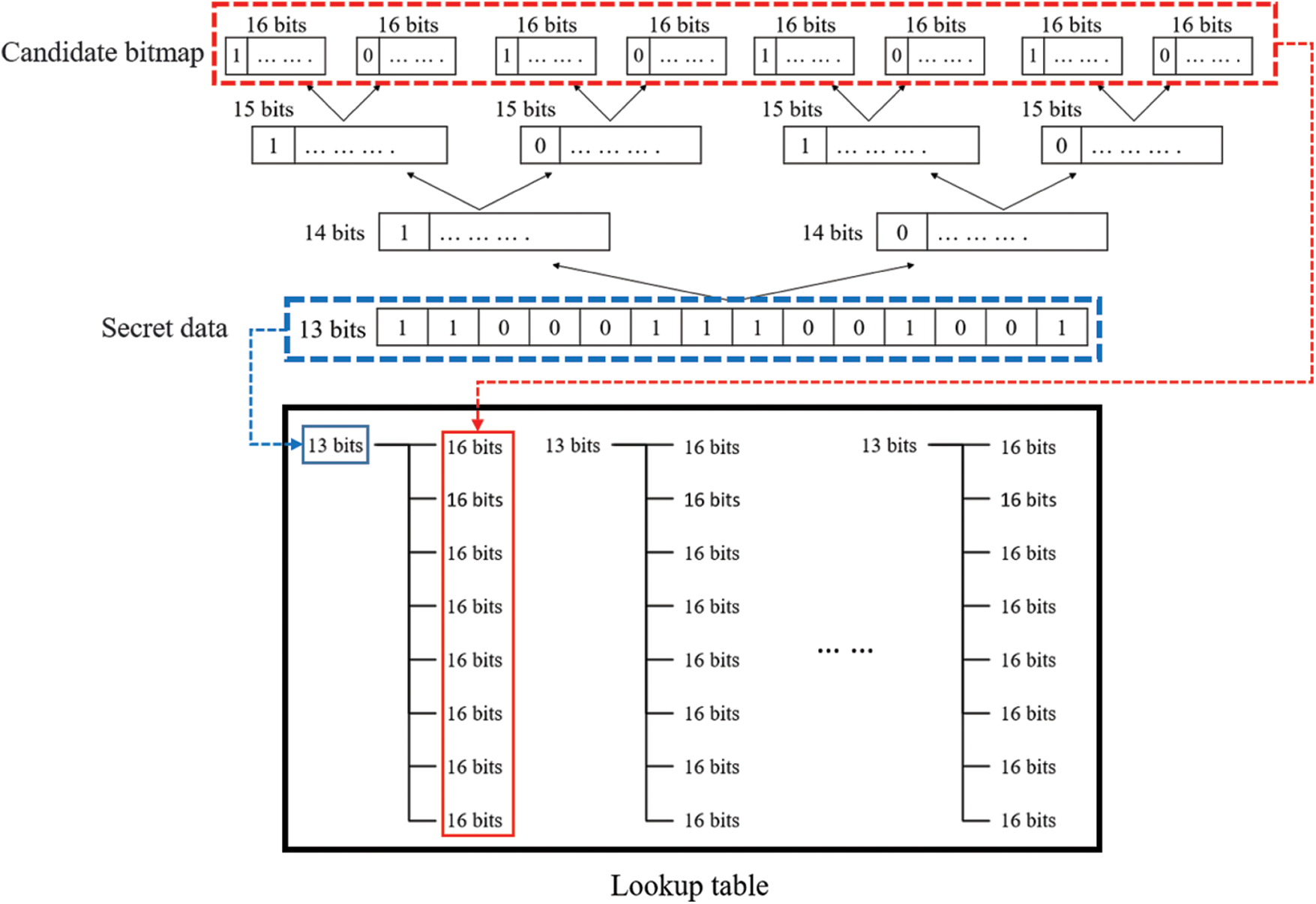
Figure 6: Schematic depicting establishment of lookup table; when the secret data to be hidden is set as 13 bits, the eight candidate bitmaps of the 16th layer can be derived using Eq. (5) to establish a lookup table in advance for subsequent use in the data hiding process
With regard to the HM and LM values of a semi-smooth block (or a semi-complex block), we employ the LSB method for data hiding; that is, we cover the LSBs of the HM and LM by following the LSB method and embed one bit into each of them. We use thresholds to separate multiple intervals and adopt different data hiding strategies to avoid scenarios where the new difference jumps to other intervals, overflows (HM = 256), or underflows (LM = −1) after the LSB method has been applied. This induces errors in the final decoding; therefore, we must set certain code rules as follows.
Consider a block in the interval T1 < D
If the new D is higher than the upper threshold, the two actions, minus one (−1) and unchanged, represent the new modification route for HM, and other two actions, plus one (+1) and unchanged, represent the new modification route for LM. If the new D is lower than the lower threshold, the two actions of +1 and unchanged represent the new modification route for HM, and the two actions of −1 and unchanged represent the new modification route for LM. In addition, in the case of a lower threshold, because HM is +1, overflow may occur. If overflow occurs, HM returns to the modification route according to the LSB method, and the two actions of −1 and −2 represent the new modification route for LM. Because LM takes the value of −1, underflow may occur. If underflow occurs, LM returns to the modification route according to the LSB method, and the two actions of +1 and +2 represent the new modification route for HM. Finally, the order-reversing method are employed to embed one-bit secret data: When the secret code is 0, the trio is saved as (HM, LM, BM). When the secret code is 1, the trio is saved as (LM, HM,
3.3 Data Embedding and Image Quality Optimization in Complex Blocks
In the embedding stage of the complex block, we employ the intra-block embedding method proposed in [18], which utilizes the block information, namely the number of high quantization levels bits (NH), number of low quantization levels bits (NL), BS, high quantization levels (HM), and low quantization levels (LM) for data hiding. The abovementioned five parameters are used to derive two hidden equations [Eqs. (7) and (8)] to embed the secret data:
where n denotes the number of bits of secret data; in this study, the default n is n = 5. After the five bits of secret data are converted into a decimal value S, S is separately compared with H1 and H2. After performing the hidden equations [either Eqs. (7) or (8)], only one with the smaller difference d is selected, the five AMBTC parameters are adjusted such that the result obtained through recalculation is equal to S. (Please refer to [18] for the details of intra-block embedding).
In the process of adjusting the parameters according to d, although there are five parameters in total, the parameters (HM, LM) are adjusted; the combinations that exceed the threshold are deleted. The MSE concept [Eq. (6)] is used to compare the remaining combinations with the original block to determine the final combinations. In this paper, after all the blocks are embedded the secret data, the modified block-based swap operator of DBS is used in complex blocks to optimize the overall image quality.
Input: AMBTC compression code
Output: AMBTC hidden code
Step 1: Read the compression code
Step 2: If HMi − LMi
Case 1: If HMi = LMi, 16 bits of secret data are extracted from S; moreover; BMi is replaced with 16 bits of secret data.
Case 2: If HMi
Step 3: If T1 < HMi− LMi
Step 4: If T2 < HMi− LMi
Step 5: If T3 < HMi − LMi, 5 bits of secret data are extracted from S and embedded into HMi and LMi by using the embedding method for complex blocks.
Step 6: Repeat steps 1–5 until all bits of secret data have been embedded.
Step 7: After data hiding is complete, perform modified block-based swap operator of DBS in complex blocks.
Step 8: Output the AMBTC hidden code
3.5 Data Extraction Procedures
Input: AMBTC hidden code
Output: Secret data S
Step 1: Read the hidden code
Step 2: If |
Case 1: If
Case 2: If
Step 3: If T1 < |
Step 4: If T2 < |
Step 5: If T3 < |
Step 6: The codes are extracted according to steps 2–5, forming the secret data S in sequence.
Step 7: Steps 1–6 are repeated until the secret data of all blocks have been extracted.
To demonstrate the superiority of the proposed method, we present a comparison between the proposed method and four other methods in this section, namely, the methods of Ou et al. [15], Kumar et al. [19], and Kumar et al. [20].
The objective measures are the human visual peak signal-to-noise ratio (HPSNR) and data capacity. We aim to demonstrate that the proposed method achieves a higher payload and superior image quality than the existing methods. Six standard eight-bit grayscale images sized 512 × 512, namely Lena, Plane, Baboon, Earth, Barbara, and Lake, were selected as the test images, as presented in Figs. 7a–7f, respectively. In the experiments, the secret data to be embedded were generated using a pseudo-random number generator with identical probabilities for bits “1” and “0”.
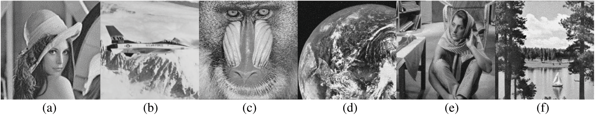
Figure 7: Test images: (a) Lena, (b) Plane, (c) Baboon, (d) Earth, (e) Barbara, and (f) Lake
The most essential consideration of this method is payload and whether the secret data will be discovered by others after encoding. Therefore, as the image quality evaluation parameter, we apply HPSNR, which integrates the characteristics of the HVS low-pass filter and the traditional PSNR. When the maximum grayscale value of the image is 255, the HPSNR can be expressed as follows:
where (H, L) indicates the image size; q indicates the HVS low-pass filter; and h and l indicate the pixel values of the input grayscale image and the resulting stego AMBTC image, respectively.
4.1 Performance Evaluation and Comparison
The four methods compared herein consider the difference D of HM − LM for determining the block classification. The methods proposed in [15,20] determine whether the block is smooth or complex by using one threshold. The method proposed in [19] determines whether a block is smooth, semi-complex, or complex by using two thresholds. The proposed method determines whether a block is smooth, semi-smooth, semi-complex, or complex by using three thresholds. Thus, we can visualize the advantages and disadvantages of each method. To enable a fair comparison, T1, T2, and T3 were set to 10, 15, and 20, respectively. The effects of different thresholds are discussed in Section 4.2. However, we selected the same parameter settings to the greatest extent possible to ensure fair comparison among the schemes considered.
Fig. 8 displays the results of the performance comparison in terms of two aspects: capacity and HPSNR. Figs. 8a and 8b present the comparison results for capacity and the corresponding image quality, respectively. The proposed method outperformed the other methods in both capacity and image quality (Fig. 8). The experimental results obtained using the six test images fully validated the effectiveness of the proposed method.
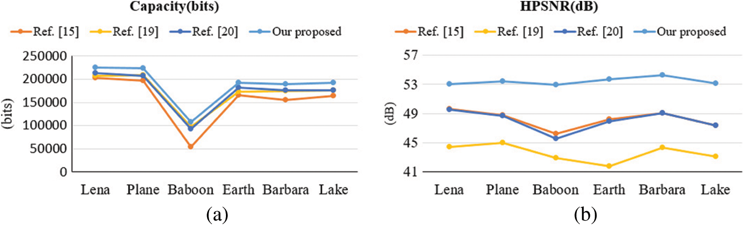
Figure 8: Comparisons among methods in terms of (a) Capacity; and (b) HPSNR by using six images
With respect to image quality, the proposed method achieved the highest quality indicator values among all methods, as shown in Fig. 8b. In the method proposed in [15], the complex block only used the interchange of HM and LM to hide one bit. Although the smooth block hid random secret data that were not related to the image content itself, it reduced distortion by recalculating HM and LM. In the method proposed in [20], the complex block was reversible; therefore, we compared the image after the complex block was reconstructed. The HPSNR was almost identical to that achieved using the method proposed in [15]. In the proposed method, although the capacity was the highest, the HPSNR did not decrease. Our data hiding scheme is XOR selective. After the secret data are processed with the XOR algorithm, the proposed method calculates the MSE of all candidate blocks, compares the values with those of the original grayscale image, and selects the closest one to replace. The method can ensure that the image has less distortion during the encoding process. Fig. 9 shows the output stego images using the proposed method.
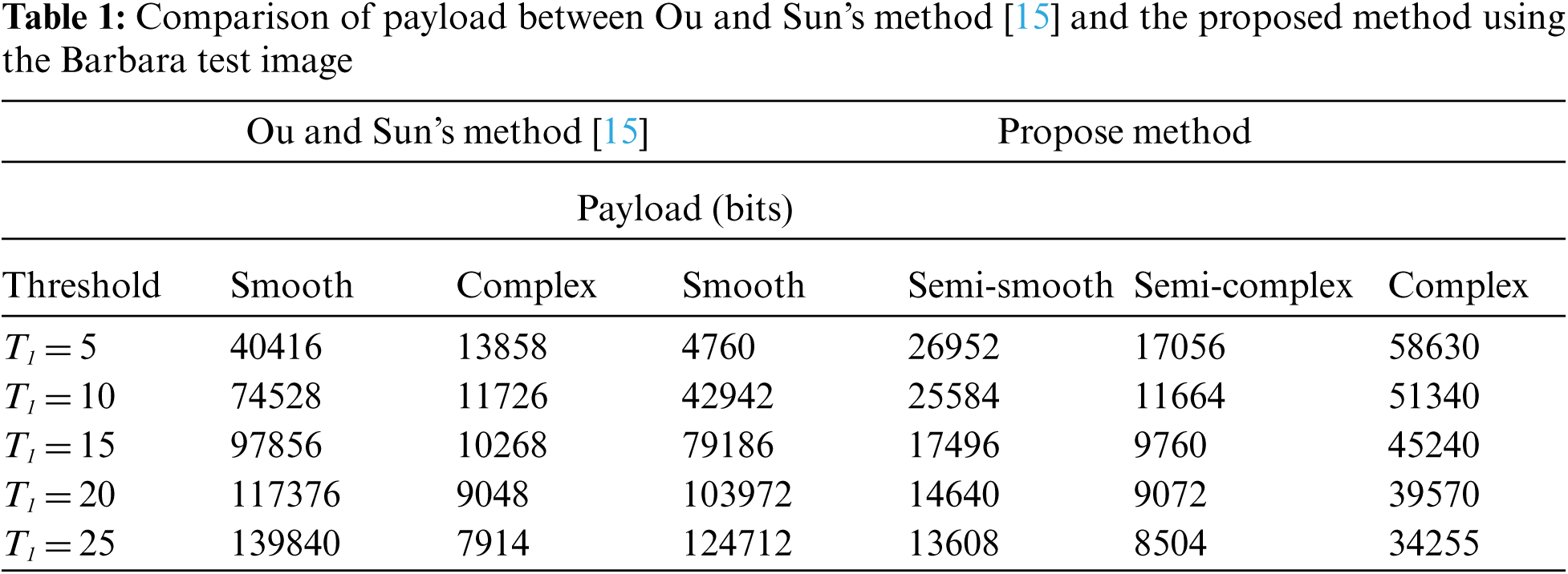
For further comparison, Tab. 1 presents the results of different threshold values obtained for the Barbara image. The smooth block of [15] corresponds to the smooth and semi-smooth blocks of the proposed method. By contrast, we apply the proposed XOR hiding method in the semi-smooth block to reduce the four-bit payload for ensuring the desired image quality. Compared to the complex blocks of [15], we consider the semi-complex blocks to increase the seven-bit payload in the proposed method. Finally, we employ the method proposed in [18] to increase the four-bit payload compared to the complex part of [15]. The greatest advantage of using the proposed four types of blocks is the fact that it facilitates the use of the most appropriate method for each block to increase the payload while reducing image distortion.
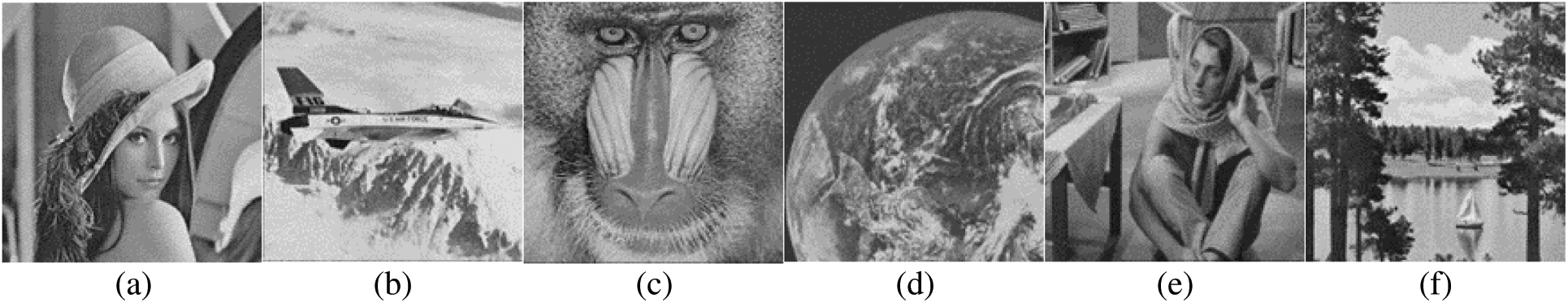
Figure 9: Output stego images using the proposed method with thresholds (T1 = 5, T2 = 10, and T3 = 15). (a) Payload = 225,328 bits; HPSNR = 53.0014 dB; (b) Payload = 223,127 bits; HPSNR = 53.4571 dB; (c) Payload = 131,530 bits; HPSNR = 52.9358 dB; (d) Payload = 192,620 bits; HPSNR = 53.7469 dB; (e) Payload = 189,117 bits; HPSNR = 54.2312 dB; (f) Payload = 192,691 bits; HPSNR = 53.1261 dB
4.2 Performance of the Proposed Algorithm in Terms of the Influence of Threshold
To compare the use of different threshold values, we compared the proposed method with four other methods. Figs. 10a–10f present the payload and HPSNR obtained using the six images, respectively. In Fig. 10, we define five groups of thresholds. Specifically, T1 is set to 5, 10, 15, 20, and 25, respectively. Compared with T1, T2 is increased by five and T3 is increased by 10. For example, in the case of the first group, T1 = 5, T2 = 10, and T3 = 15. The proposed method achieves both the highest capacity and the most favorable image quality at different threshold values.
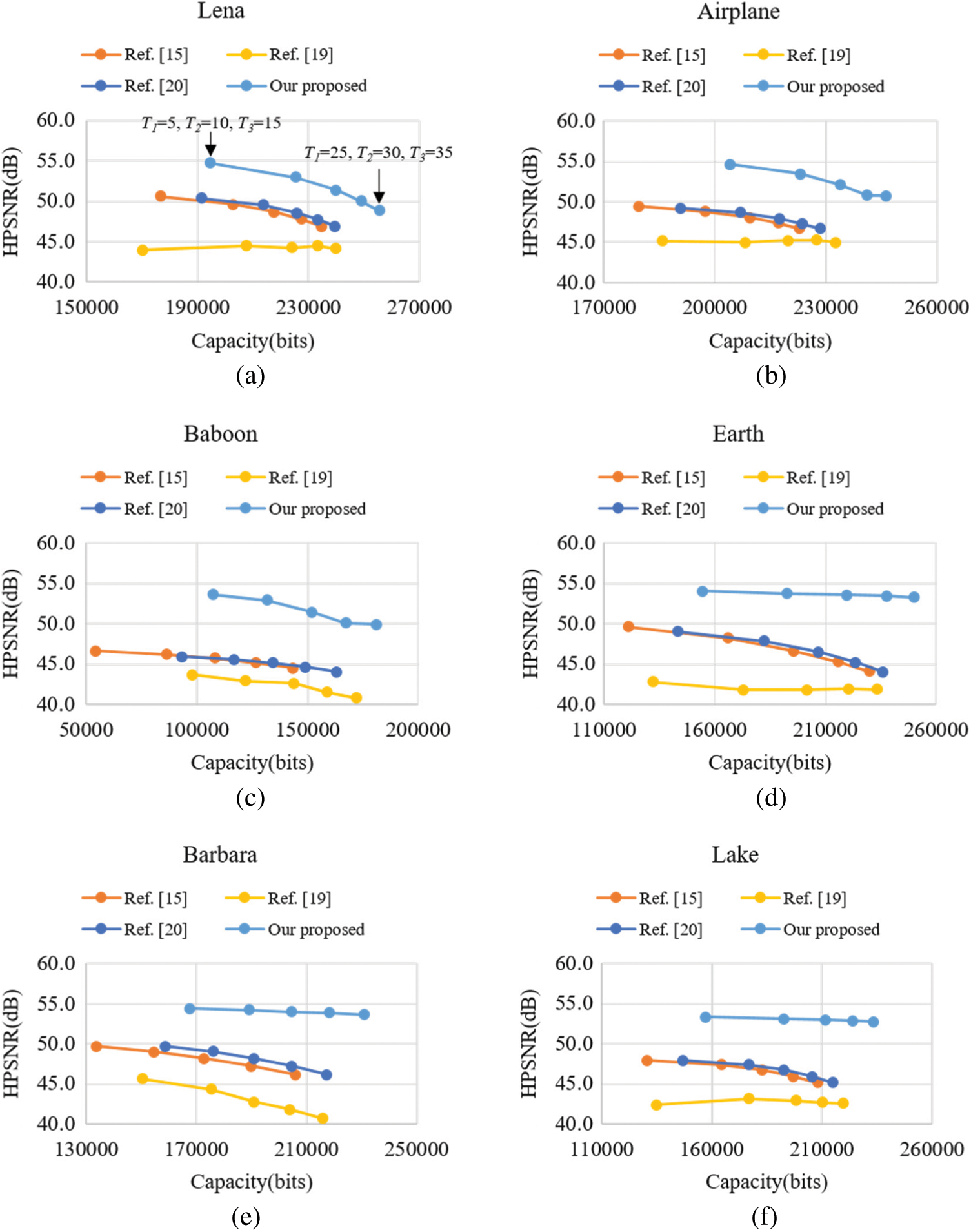
Figure 10: Comparison of HPSNR vs. payload between the methods proposed in [15,19,20] and the proposed method. (a) Lena, (b) Plane, (c) Baboon, (d) Earth, (e) Barbara, and (f) Lake
With respect to the influence of T1, because it is used to select smooth blocks, in Fig. 10, a larger T1 leads to more smooth blocks and a higher payload. For images with a large number of complex blocks (e.g., Barbara, Earth, and Lake), as the threshold increases, although the HPSNR gradually decreases, the reduction is not as considerable as that in the other methods because the proposed method can select the data closest to the original grayscale image from a large amount of data to replace. This phenomenon is most obvious in the case of images with numerous complex blocks.
In smooth blocks, because the difference between HM and LM is not substantial, even if the bitmap is directly replaced, the image quality will not be notably affected. By contrast, in complex blocks, because the difference between HM and LM is large, if the bitmap is modified, it will have a substantial effect on image quality. The method proposed in [15] uses the interchange of HM and LM to hide information in the complex block, which does not affect the complex block. The method proposed in [15] ensures that the complex block is reversible, meaning that the effect on the complex block is almost identical to that of the method proposed in [20]. The proposed method uses the XOR operation to concurrently hide the secret data and reduce image distortion. Subsequently, it employs DBS technology for adjusting image quality. Therefore, compared with the smooth block, the reduction of image distortion is obvious for complex blocks. Consider the example of the Baboon image, which has the most complex blocks. Even if the HPSNR decreases slightly as the threshold increases, the result remains considerably superior to those obtained using the other four methods. Thus, the superiority of the proposed method can be confirmed.
Fig. 11 presents an example for visual comparison, in which the bottom left corner is an enlargement of part of the image, used for the perceptual demonstration of image quality. In Fig. 11, we can see the black line near middle of an enlarged view in the Baboon image. The line is only slightly blurred compared with that in the original image. If we do not compare it with the original Baboon image, it is difficult to identify what has been modified. The other four methods led to slight discontinuities at the edge of the image, making it easier to observe that the image has been modified. Therefore, the proposed method is superior to the other four methods in security.
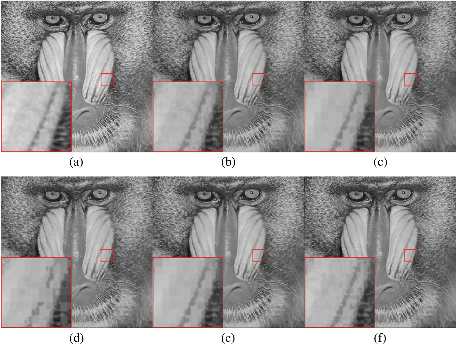
Figure 11: Results of visual comparison using the test image Baboon (T1 = 25, T2 = 30, and T3 = 35). (a) Original grayscale image. (b) AMBTC image. (c) Result of [15]. (d) Result of [19]. (e) Result of [20]. (f) Result of the proposed method
In this paper, we propose an irreversible data hiding method for AMBTC-compressed images. This method divides blocks into four types, and thus we can select different appropriate data embedding methods according to the characteristics of each block type. Moreover, this work employs DBS to reduce image distortion. The experimental results indicate that the proposed method yields higher image quality and hiding capacity compared to the methods that use threshold classification. In summary, the advantages of the proposed method are as follows:
1. Compared with the traditional block classification (i.e., two types: smooth and complex), the proposed method defines four block types, and designs different data hiding methods accordingly to increase the hiding capacity.
2. By means of the XOR operation, the secret data are hidden in the bit relationships of the bitmap instead of directly replacing the bitmap, thereby increasing the security level of encryption.
3. In the proposed selective XOR hiding scheme, multiple candidate bitmaps are considered at the same time, which can prevent the severe image distortion during the data hiding process.
Funding Statement: This work is funded in part by the Ministry of Science and Technology, Taiwan, under grant MOST 108-2221-E-011-162-MY2.
Conflicts of Interest: The authors declare that they have no conflicts of interest to report regarding the present study.
1. M. Lema and O. Mitchell, “Absolute moment block truncation coding and its application to color images,” IEEE Transactions on Communications, vol. 32, no. 10, pp. 1148–1157, 1984. [Google Scholar]
2. A. Malik, G. Sikka and H. K. Verma, “A high payload data hiding scheme based on modified AMBTC technique,” Multimedia Tools and Applications, vol. 76, no. 12, pp. 14151–14167, 2017. [Google Scholar]
3. Y. Y. Chen, C. H. Hsia, S. Y. Jhong and H. J. Lin, “Data hiding method for AMBTC compressed images,” Journal of Ambient Intelligence and Humanized Computing, 2018. [Google Scholar]
4. R. Bhardwaj and A. Aggarwal, “Hiding clinical information in medical images: An enhanced encrypted reversible data hiding algorithm grounded on hierarchical absolute moment block truncation coding,” Multidimensional Systems and Signal Processing, vol. 31, no. 3, pp. 1051–1074, 2020. [Google Scholar]
5. W. Zheng, C. C. Chang, J. H. Horng, J. Lin and Y. Shi, “An adjustable RDH method for AMBTC-compressed images using unilateral pixel value modification strategy,” Journal of Network Intelligence, vol. 5, no. 2, pp. 77–92, 2020. [Google Scholar]
6. Y. H. Chen, C. C. Chang, C. C. Lin and Z. M. Wang, “An adaptive reversible data hiding scheme using AMBTC and quantization level difference,” Applied Sciences (Switzerland), vol. 11, no. 2, pp. 1–13, 2021. [Google Scholar]
7. C. C. Chang, X. Wang and J. H. Horng, “A hybrid data hiding method for strict AMBTC format images with high-fidelity,” Symmetry, vol. 11, no. 10, pp. 314, 2019. [Google Scholar]
8. Z. Yu, C. C. Lin, C. C. Chang and G. D. Su, “HBF-DH: An enhanced payload hybrid data hiding method based on a hybrid strategy and block features,” IEEE Access, vol. 7, pp. 148439–148452, 2019. [Google Scholar]
9. J. Lin, C. C. Lin and C. C. Chang, “Reversible steganographic scheme for AMBTC-compressed image based on (7, 4) hamming code,” Symmetry, vol. 11, no. 10, pp. 1236, 2019. [Google Scholar]
10. C. Kim, D. Shin, C. N. Yang and L. Leng, “Hybrid data hiding based on AMBTC using enhanced hamming code,” Applied Sciences (Switzerland), vol. 10, no. 15, pp. 2911, 2020. [Google Scholar]
11. L. Li, M. He, S. Zhang, T. Luo and C. C. Chang, “AMBTC based high payload data hiding with modulo-2 operation and hamming code,” Mathematical Biosciences and Engineering, vol. 16, no. 6, pp. 7934–7949, 2019. [Google Scholar]
12. W. Zheng, C. C. Chang and S. Weng, “A novel adjustable RDH method for AMBTC-compressed codes using one-to-many Map,” IEEE Access, vol. 8, pp. 13105–13118, 2020. [Google Scholar]
13. Z. Hui and Q. Zhou, “A novel high payload steganography scheme based on absolute moment block truncation coding,” Multimedia Tools and Applications, vol. 79, no. 33–34, pp. 24241–24264, 2020. [Google Scholar]
14. J. Y. Yeh, C. C. Chen, P. L. Liu and Y. H. Huang, “High-payload data-hiding method for AMBTC decompressed images,” Entropy, vol. 22, no. 2, pp. 145, 2020. [Google Scholar]
15. D. Ou and W. Sun, “High payload image steganography with minimum distortion based on absolute moment block truncation coding,” Multimedia Tools and Applications, vol. 74, no. 21, pp. 9117–9139, 2015. [Google Scholar]
16. W. Hong, T. S. Chen, Z. Yin, B. Luo and Y. Ma, “Data hiding in AMBTC images using quantization level modification and perturbation technique,” Multimedia Tools and Applications, vol. 76, no. 3, pp. 3761–3782, 2017. [Google Scholar]
17. J. Mathews and M. S. Nair, “Adaptive block truncation coding technique using edge-based quantization approach,” Computers and Electrical Engineering, vol. 43, pp. 169–179, 2015. [Google Scholar]
18. Y. H. Lin, C. H. Hsia, B. Y. Chen and Y. Y. Chen, “Visual IoT security: Data hiding in AMBTC images using block-wise embedding strategy,” Sensors (Switzerland), vol. 19, no. 9, pp. 1974, 2019. [Google Scholar]
19. R. Kumar, D. S. Kim and K. H. Jung, “Enhanced AMBTC based data hiding method using hamming distance and pixel value differencing,” Journal of Information Security and Applications, vol. 47, pp. 94–103, 2019. [Google Scholar]
20. N. Kumar, R. Kumar, A. Malik and S. Singh, “Low bandwidth data hiding for multimedia systems based on bit redundancy,” Multimedia Tools and Applications, 2021. [Google Scholar]
 | This work is licensed under a Creative Commons Attribution 4.0 International License, which permits unrestricted use, distribution, and reproduction in any medium, provided the original work is properly cited. |