DOI:10.32604/cmc.2022.023556
| Computers, Materials & Continua DOI:10.32604/cmc.2022.023556 | |
| Article |
Man Overboard Detection System Using IoT for Navigation Model
1Department of Information Systems Engineering, Mugla Sitki Kocman University, Mugla, Turkey
2Artificial Intelligence Lab, Department of Computer Engineering, Gachon University, Korea
*Corresponding Author: Taegkeun Whangbo. Email: tkwhangbo@gachon.ac.kr
Received: 12 September 2021; Accepted: 01 November 2021
Abstract: Security measures and contingency plans have been established in order to ensure human safety especially in the floating elements like ferry, ro-ro, catamaran, frigate, yacht that are the vehicles services for the purpose of logistic and passenger transport. In this paper, all processes in the event of Man overboard (MOB)are initiated for smart transportation. In MOB the falling person is totally dependent on the person who first saw the falling person. The main objective of this paper is to develop a solution to this significant problem. If a staff member or a passenger does not see the fall into the sea, undesirable situations such as disappearance, injury and death can occur during the period until the absence of the fallen person is noticed. In this paper, a comprehensive and improved solution is provided in terms of personnel and passenger security especially in all the floating elements, in which human resources are intensively involved like passengers, freight, logistics, fishing, business, yacht, leisure and naval vessels. In this case, if the ship's personnel or passengers fall into the sea in any way, it detected the fallen person into the sea by the sensors in the portable emergency device, which each person will carry. The warning system is activated via the in-ship automation system to which the information is transmitted by wireless communication. Thus, the case of MOB will be determined quickly. Internet of things (IoT) has a key role in identifying the location and information of the person falling into the sea through sensors, radio frequency, GPS and connected devices. Simultaneously, the alarm system on board will be activated and MOB flag (Oscar) will automatically be opened. This paper enables the Search and rescue (SAR) operations to be initiated and accelerated without losing time through decision-making process.
Keywords: SAR; internet of things; man overboard; arduino; wireless communication; smart transportation
The United States Coast Guard conducted 39,486 Search and rescue (SAR) operations in 2001. However, the SAR drops to 16,845 in 2020 out of which 21,050 are assisted and 4,286 are saved from the possible threat [1,2]. For centuries, the most prominent fear is falling overboard at sea, and due to the advancement of technology, this issue can be limited. Different technological devices are used like MOB detection transmitters, life rings, rescue buoys, trailing lines, etc. However, their applications are limited for a certain situation and specifically sized vessel.
The MOB situation can be handled securely if the falling person is noticed by the other members on the board [2]. On the other hand, it can be critical if the MOB situation is not noticed because no one will be aware of the identity of the fallen personnel, drop time, exact coordinate when it falls on. The inability to reach onboard situation is a problem experienced during the detection and rescue of the personnel or passengers. This information is vital to a search and rescue operation. Because the person that fell into the sea may have lost consciousness or hypothermia may have occurred. Subsequently, this may result in death due to serious causes such as suffocation and heart attack [3].
If MOB situation is not seen under normal conditions, then it is almost impossible to rescue the fallen person. Depending on the type of ship, this may take at least 5–20 min. During this period, the person who falls may experience suffocation, loss of consciousness, hypothermia, etc.
Due to some limitations of the technological devices, there is a need for a specific rescue device or module that is capable of search and rescue operation. In this paper, a MOB detection system (DADTS) module is designed for overboard floating elements. The module can be used by the passengers in MOB situations. The incoming signals and information are transferred to the automation system with Radio frequency (RF) receivers on the ship through wireless [4–8] and mobile ad-hoc network [9–11] to form an information and decision-making structure. In this way, it organizes the rescue activity in a faster and more conscious way.
The organization of the paper is as follows. In Section 2, related work for the overboard situation is explained with some possible solutions. Section 3 is describing the methodology of the paper along with the overview and method. Section 4 is describing the hardware and the software platform for the implementation. Section 5, explain the result discussion and the data collection. Finally, Section 6 concludes the paper.
The robotic path planning solutions [12–14] considered the surrounding view of the environment and need more information about the accident. The SAR teams usually use the planner to determine the area of accident for MOB situations. The operation starts at the center of SAR, and the search area increases with time as the man in water is not founded. As a result, the probability of finding a person decreases and increases the cost. Similarly, this approach is more costly with less reliability due to the use of Unmanned arial vehicle (UAV) for SAR [15].
In this paper [16], a MOB positioning system is discussed which is based on measurement of Received signal strength indicator (RSSI) between smart life vest tags and UAV. This method uses multiple SAR operations at a time with an improving positioning system within 500 m × 350 m.
The approach used in [17] is working on underwater robots for overboard situation. İt is using raspberry Pi for SAR and therefore it is less effective for longer duration and long-range detection. Similarly, the complication further increases due to high underwater pressure and against strong water current.
In this paper [18], a drone is used by the US navy in visual navigation for MOB during search and rescue operations especially in a marine situation where the number of casualties increases. Unmanned surface vehicles (USV) are also used along with the drone to efficiently perform SAR operations during the shortage of manpower and in the emergency rescue phase.
In this paper [19], an improved version of the Automation identification system (AIS) is proposed for the MOB situation. AIS consists of transponders and receivers and it uses 161.975 and 162.025 MHz radio frequencies for the detection, identification, and communication between the victim and ship. İt uses the Direct digital synthesizer (DDS) and Gaussian minimum shift keying (GMSK) to stabilize the antennas and Very high frequency (VHF). When the MOB situation occurs then an alarm is activated to transmit the GPS position to the nearest ship within the range of the AIS.
In this paper [20], a reliable SAR device is used to find the man in the water and it is very efficient during SAR missions. This device is an all-in-one package because the various state-of-the-art technologies are available in this device like marine battery technology, sonar technology, database synchronization, wireless, GPS technology. With the help of this technology, important information related to MOB can be received reliably. Similarly, the long life of marine battery life increases the duration of the search. This device can work in a harsh environment like high wind speed, current speed, high wave resistance, a longer duration for SAR, and quick access to the MOB situation. This device is very complicated due to the combination of various techniques and can be limited to big ships or warships.
Advancement in technologies and research increases the life-saving situation for MOB. Many industries are making onboard systems but still, many improvements are required in terms of reliability and cost. The previous approaches as discussed having limitations and still need the progress in SAR situation. İn the proposed method, a searching, detection, identification, and rescuing of a person in the water is implemented. This will provide 24 h monitoring, safety, and satisfaction to the man onboard through sensing, monitoring, Global positioning system (GPS), RF, and virtual warning system.
3.1.1 Maneuver and Warning Sign
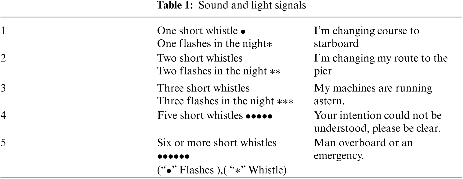
The marine coast guard uses few protocols to avoid the collision by whistling at least five short and rapid signals. This sign can also be used for warning purposes, preventing the passage of a power-driven vessel navigating in a narrow channel, path, or traffic line, or similar situations. Forces conducted maneuvers when a boat cruises according to these rules in the case Tab. 1 as specified in horn lights indicates by giving mark [20].
• The first person to see the person overboard said, “The man fell overboard.” He must shout to warn those on board. Even if alone on board, he should shout to encourage the casualty. It is announced, by specifying the direction of the MOB from the general announcement circuit.
• To prevent the falling man from injury, the ship propellers must be stopped immediately by shutting off the engine.
• It is difficult to see and hear a person falling into the sea among the waves. For this reason, observers should not take their eyes off the victim.
• The ship position must be recorded immediately, especially in night cruising and harsh sea and weather conditions.
• The position where the crew fell is automatically recorded by pressing the MOB button on the GPS.
• A signal buoy with the letter “O” should be thrown into the water.
• Floating aids such as life jackets, lifebuoys, fenders that can be helpful should be thrown to the casualty. The more of these materials, the better. It both helps the casualty and shows the approximate place where he fell.
• A flashlight or projector should be on top of the man in water to prevent them from disappearing if the accident occurred at night.
In this section, MOB detection system is designed. The system in case of MOB to be active, started the communication and data transfer between the floating elements and the decision support system respectively as shown in Fig. 1. First, arduino nano was used in a waterproof armband that individuals would carry on them, and it was programmed using its own libraries in the arduino IDE development environment, compiled and uploaded to the arduino. Arduino uno card is used in our receiver module, which is located in the open area on the floating element. Its own IDE environment was used for the card in question.
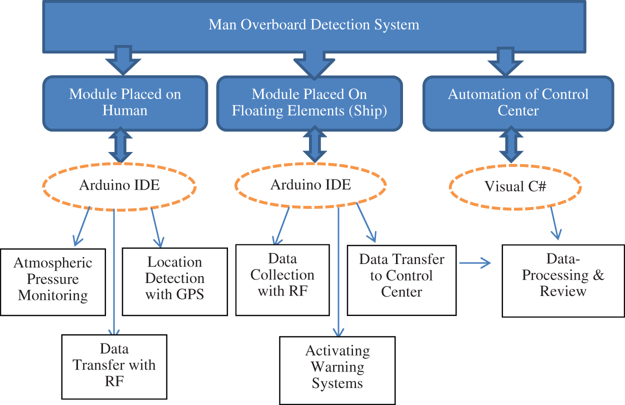
Figure 1: Man overboard detection system working steps
Floating part of the decision support system connected to the display of information which is important due to the serial port receiver not arduino windows operating system wherein there is provided a computer. It is ensured that the signals sent via RF modules on the said screen become readable and meaningful. The data collected by parsing creates a support system with the ability of display, parsing, warning and decision making with the software designed in the C# environment.
3.2.1 Arrange on the Individual Sender (TX) Module Design
It is designed to broadcast from the 433 MHz frequency band via the RF module by the pressure, altitude, and temperature information from the BME280 sensor [21,22] if the trigger event sequence of the module is placed in the waterproof case occurs. The module was designed based on arduino with the open-source arduino IDE interface and the methods specified in the sub-items.
3.2.2 Atmospheric Pressure Monitoring Method
BME280 sensor from bosch is using for atmospheric pressure monitoring. Bar is a unit of pressure defined as 100,000 Pa and approximately equal to atmospheric pressure at sea level. The value read from the pressure sensor is in Pa (Pascal) type. Pressure values are in millibars and the sensor value for millibar conversion is in Eq. (1).
The bme.readTemperature method is using to calculate the ambient temperature value. The related method returns a value in Celsius (centigrade). In arduino, it returns a float value by taking the temperature value in the getTemp() function. By sending the temperature value to the automation software, inferences were made about the health status of the individual who fell into the sea.
The pressure value is using to calculate the height to sea level. The pressure value expressed in Eq. (1) is depending on the height of the individual relative to the sea level. Pressure usually decreases with altitude and increases rapidly near ground level. If a person goes up in the atmosphere, the weight of the air on that person decreases. Pressure increases rapidly at near-ground levels due to the increase of gases near the ground and the effect of gravity. pressure at sea level; 1 Atmosphere = 1.01325 bar = 1013.25 millibar (mb) = 101326 Pascal = 1013.25 hectopascal(hPa) = 29.92 in.Hg = 760 mm Hg = 14.7 Lb/inch (ADB, 2017). It is calculated within the library using Eq. (2) using instantaneous atmospheric pressure value and sea level pressure value.
To determine the MOB situation, the height of the individuals to the sea level is using along with the pressure. On arduino, when the drop event occurs, it starts or continues the broadcast by changing the bool value of the “status” variable from “false” to “true” at the beginning. The purpose of using this variable is that the pressure and altitude values can return to normal if the individual who falls into the sea stays above sea level or stays on the water. While individuals are on floating elements, they are placed very close to sea level (1–10 meters). For this reason, the pressure value is calculated close to the sea level pressure value and the altitude to the sea level. The values shown in Fig. 2 are checked for the detection of the fall situation.

Figure 2: Fall detection rule
In order to determine whether the case of falling overboard has occurred;
• Real-time pressure detection
• Real-time sea level elevation detection
• Control of the occurrence of the overboard incident
• Packing the data to be sent to the Receiver (RX) module in DADTS format
• It is the sending of the packed data via the Sender (TX) RF module.
3.2.3 Atmospheric Pressure Monitoring Method
Within the scope of our study, NEO6M GPS and OPEN Smart modules were used. Thanks to the GPS and compass features on this module, it is frequently used in drone systems. GPS module and arduino connection are designed to a module on the individual, and the compass connection is disabled to reduce the power consumption of the GPS module. It is necessary to determine the RX and TX pins and baud rate values to ensure communication between the GPS module and the arduino.
3.2.4 RF Communication Method and Data Packaging Method
The RF modules used in this paper are simplex working modules. In this system, the sender (TX) RF module is used. Within the scope of the paper, there was a need to combine the data obtained from the sensors by processing them in a certain format in order to ensure the integrity and not be corrupted. In this context, the information to be packaged like device code, real-time pressure value, real-time temperature, real-time location information.
3.2.5 Computer-Aided Design of Transmitter Module (TX) Hardware
The transmitter module design was first designed with fritzing software and connections were made. It was mounted on printed circuit boards specific to the design drawn by removing the necessary materials. The drawing example made is shown in Fig. 3.
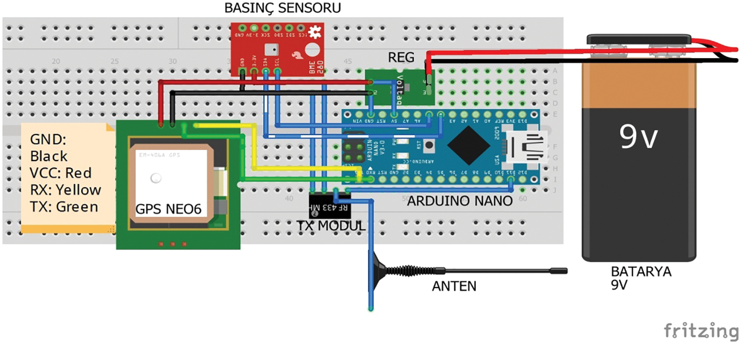
Figure 3: Transmitter (TX) module design drawing
3.2.6 Receiver (RX) Module Design that Places on a Floating or Fixed Control Point
The information of the person who fell as a result of the MOB situation is obtained by means of sensors and the obtained data is packaged and sent through radio frequency modules and is systematically cycled. One of the most important stages of this cycle is to collect the TX signals and to obtain the data on them. In accordance with the content of the obtained dataset, the automation system was given the task of transmitting data and activating the alarm systems. The number of receiver modules can be different depending on the size of the floating element. For example, 5 sensors can be used between the bow and stern of a 200-meter-long ship. In this case, one module is considered the coordinator, and the others are considered endpoints. By transmitting the RF signals detected from the endpoints to the coordinator receiver, a sensor network is formed. An example of positioning the sensor on the floating element is shown in Fig. 4. Now it is possible to decide from which side of the floating element the falling person fell. If a single receiver sensor detects the receiving module, it can be assumed that the module falls in the direction it is in. If more than one module detects the signal sent by the TX module on the person who fell, the module with the earliest detection time can be detected and the direction of the fall can be decided. If more than one module is to be used, the RF modules must support bidirectional communication.
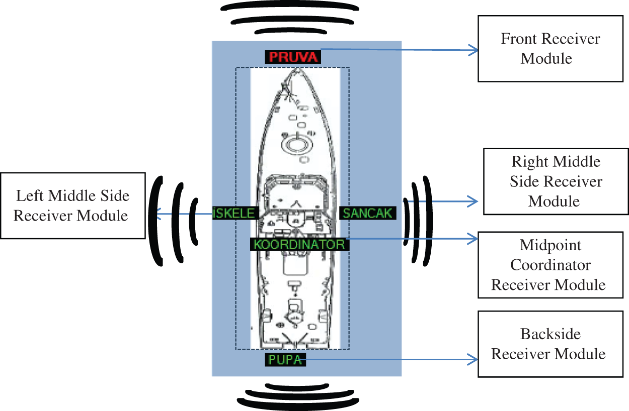
Figure 4: Multiple receiver sensor modules positioning in the ship
Arduino is simple to use and in code-writing, which allows making many applications and results in a very short time. In fact, thanks to the software called a bootloader, programming can be done through the serial port. Within the scope of the paper, arduino nano and Uno models were used. BME280 with the sensor of the Bosch company can operate stably in order to digital pressure measurements and pressure sensor has been utilized. Only the GPS, part of the Ublox NEO-6M GPS module is used in the system in order to detect the position of the person who fell overboard. RF modules operating in the 433 MHz frequency band are used to communicate with the arduino located on the object falling into the sea and on the shipping platform. RF modules are configured to operate as point-to-point. arduino Uno-Nano models are powered by 5 V voltage. In order to prevent the receiver system placed on the shipping platform from being affected by rain and wind, IP S −65 ABS sealed waterproof boxes are used. Its own language and libraries of sensors were used in the coding of arduinos. The automation software prepared for the purpose of separating, marking, and selecting who, where and when the person fell on the side of the ship was prepared in C#. Google MAPS infrastructure is used for location marking.
The arduino platform basically uses ATMEL microcontrollers in the field of electronics and programming with its libraries. arduino is an open-source platform that arduino's all products as shown in Tab. 2, related software, and its design has been explicitly shared with everyone.
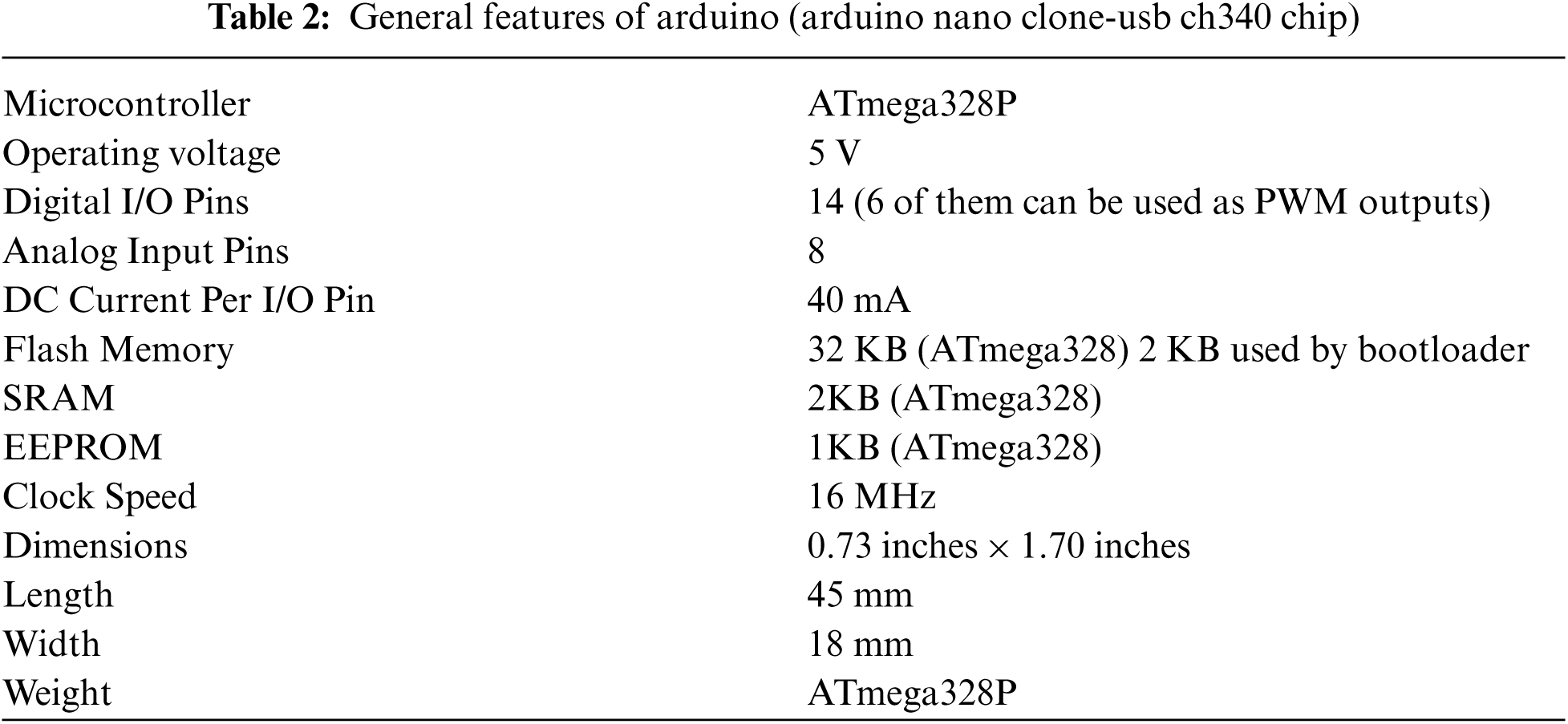
The arduino Nano is the model [23], which basically has the same features as the arduino Uno but is much smaller in size. It uses the ATmega328 microcontroller like the arduino Uno. Thanks to the similarities with the Uno, we can use any software written for the Uno with the Nano as we wish. The nano model was used as a sensor and transmitter (TX) node on the person due to its small size and small footprint.
Equipped around the ship by receiver modules, it works continuously in listening mode. If a data packet of the specified size is detected, it receives the data packet and sends it over the serial port. The automation system in the floating element operations center is constantly listening through this serial port. If the receiving module has captured a packet, it receives the relevant packet and processes it in the automation system. The data packets collected by the RX module during the test phase are shown in Fig. 5. When the sample data packages are examined, it is seen that the size of the incoming packages is 31 characters. Collecting data packets is started by taking this number into account.
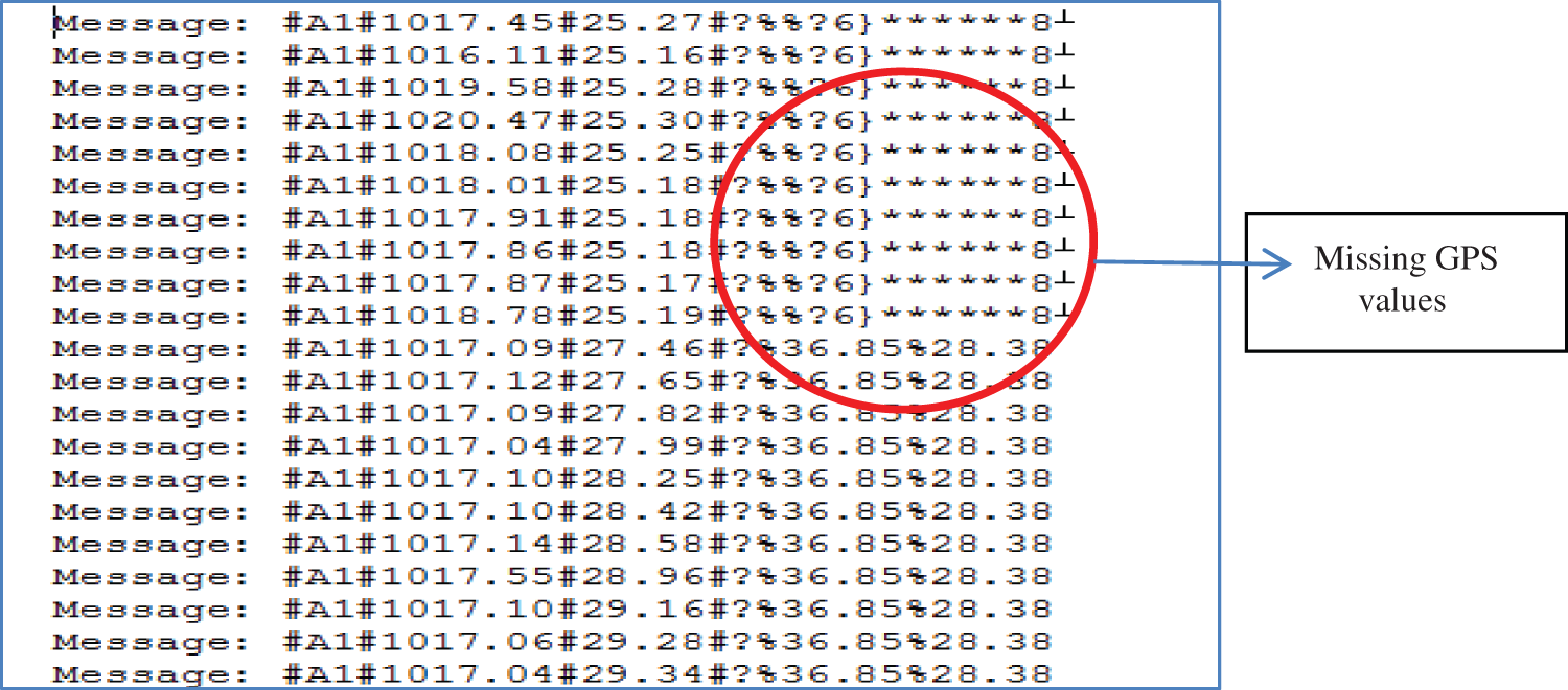
Figure 5: Data packets collection during test phase
5.2 Design of Onboard Automation System
Automation is the automatic process of doing things without human intervention in industry, management, and scientific work. In other words, sharing work done between humans and machines is called automation. The designed automation is divided into Control of receiver (RX) modules, listening to defined serial ports, data query from database, location marking on the map, time calculations and the designed interface screen view is shown in Fig. 6.
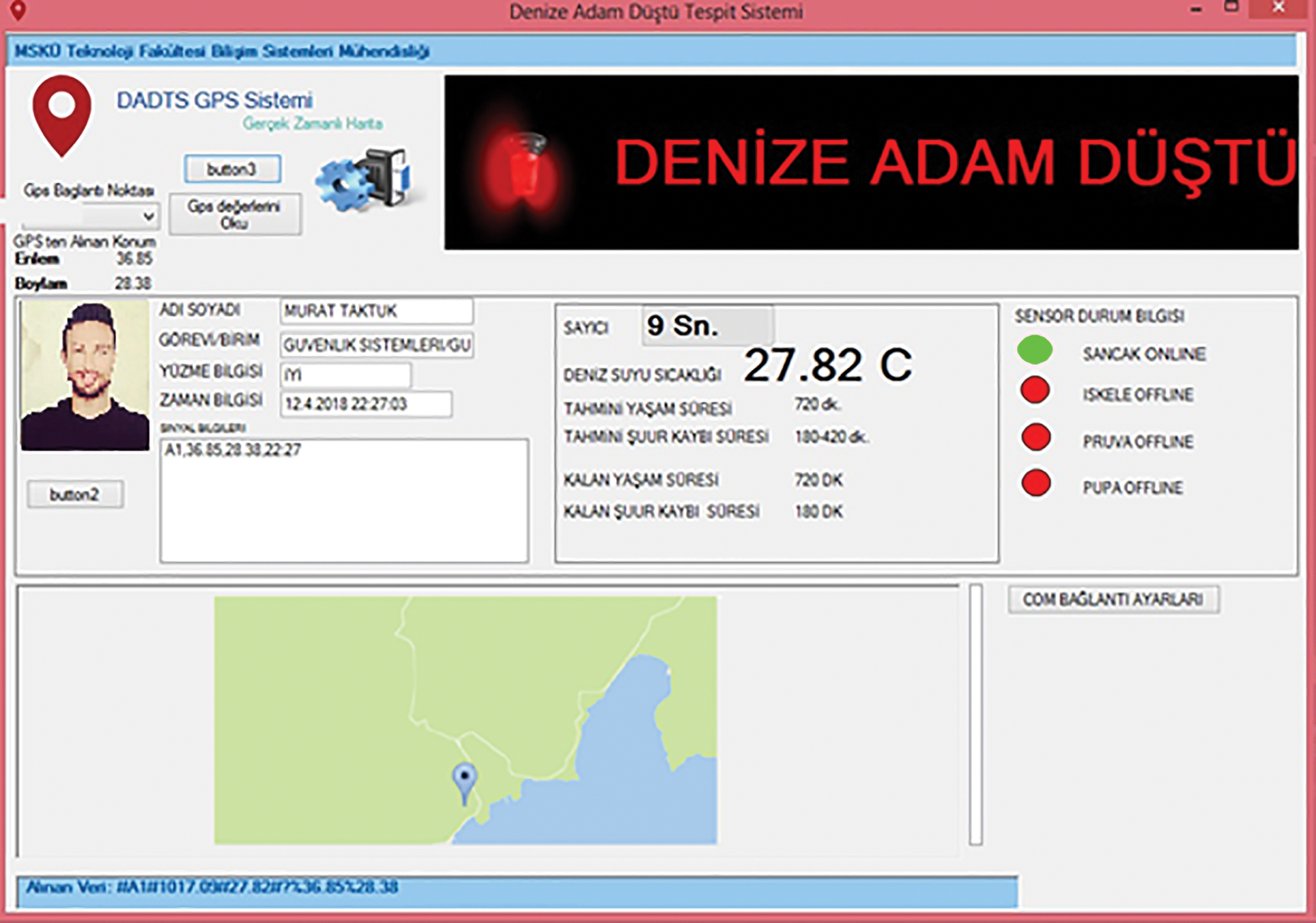
Figure 6: Automation interface screen
In serial port listening status, a COM port is assigned to each receiver module, if the receivers connected to the control center are directly connected to the control center via USB. COM port assignment operations is executed from the parameters form. If the COM port selected from the list in Fig. 7 is accessible, the LED on the same line will turn green after the selection.
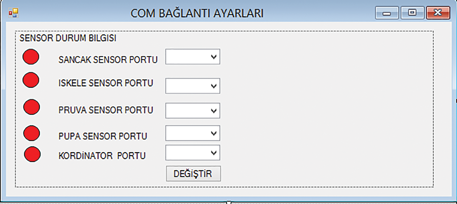
Figure 7: Connection settings of COM ports
5.4 Querying Data from Database
When the data packet received over the receiving module is split according to the “#” sign, the first received value is the personal id code and the id is registered in the database. This information is using as identity information, picture, place of duty, swimming information, etc., and will be queried according to the id number of the person who fell and will be displayed on the screen as shown in Fig. 8. At the same time, a database connection is using to log the received data packets.
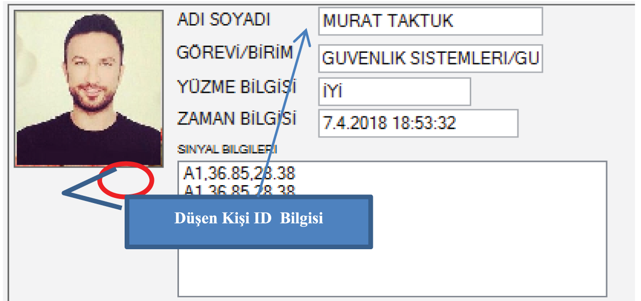
Figure 8: Fallen person information queried from the database
In the event of a MOB, the GPS module in the sender (TX) module on the person overboard adds the location information as latitude and longitude information to the data packet. If the location information cannot be obtained in any way, the location will be obtained from the backup GPS module that we have connected to the receiver (RX) module. The data packet collected by the receiver module is transferred to the control center via serial connection. The automation software in the control center computer parses the data packet it receives and receives the GPS data. Using the “Google static MAP api”, the location data it receives can be marked as shown in Fig. 9. The “%” sign is used to prevent the location information from being mixed during the split process of the data packet.
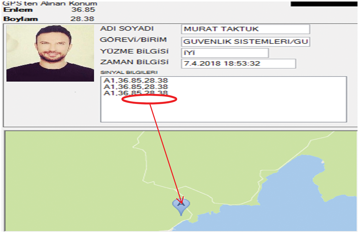
Figure 9: Location marking according to data packet received in the automation software
5.6 Calculating Time Information
When the data package received by the receiver module is examined, the ambient temperature information is obtained from the sensor on the person falling into the sea. After this information is splitting from the data package, it will form a reference value for vital situation detection and decision making.
After the first signal, the water temperature and the GPS data are collecting from the sensors. The signal of the fallen personnel is continuously transmitting to the computer. The designed software will start the time counter by triggering the first signal from the personnel falling according to the seawater temperature, and it is planned to instantly display the information messages (average lifetime, remaining time, GPS location, etc.) to the operation's center users according to the rule-based values. The overall working simulation of the system is shown in Fig. 10.
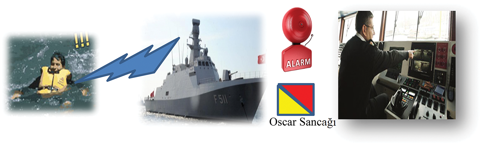
Figure 10: Representative system simulation
5.7 RF Communication Distances and Atmospheric Pressure Measurement Values
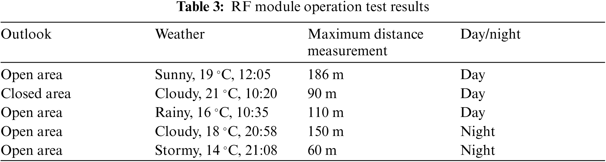
The RF communication modules are using for short-range testing in this paper. TWS-BS-3 RF module series operates in the 433.92 MHz frequency band. The test data obtained are shown in Tab. 3. The communication distances in question are offering in HM-TRLR-S series 433 MHz modules at a distance of 1 km in the open area and sunny weather.
Atmospheric pressure measurement is the key point in this paper. In Marmaris town, the tests were conducted under normal conditions, the average pressure value at sea level was 1017.0. The values are obtained, when the pressure measurement is below sea level as shown in Tab. 4.
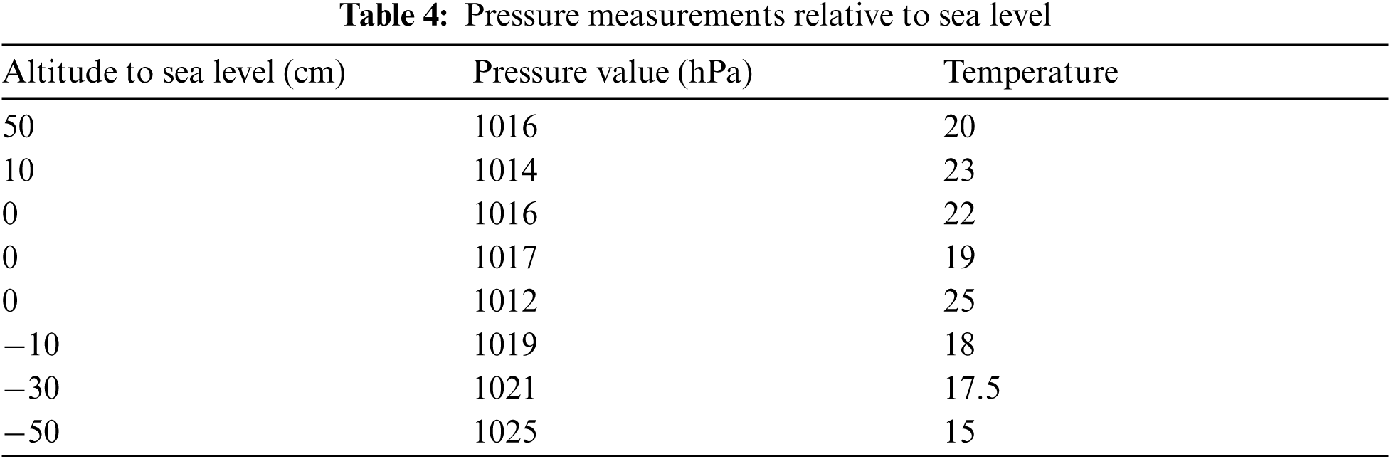
According to the values obtained, the atmospheric pressure at sea level for the Marmaris region is measured between 1010–1018 hPa depending on the changes in air temperature. An atmospheric pressure change occurs every 10 meters under the sea. However, in MOB situation, the person sinks 50–100 cm into the water depending on his weight, or in a life jacket he sinks up to 100 cm. The underwater pressure value is between 50–100 cm and it rises above 1025 hPa. The pressure value from the pressure sensor is constantly checked. When a value of 1025 hPa and above is detected, a MOB can be considered.
As a result of combining and packaging the data obtained from the sensors, it is transferred with RF modules. Data packets contain a maximum of 31 characters. When each character is evaluated as 8 bits, i.e., 1 byte, the size of our data packet will be 248 bits. The Data Rate value of the RF modules used is 8 Kbps and 8000 bits per second can be transferred.
Although this paper is mainly for the detection of MOB in sea vehicles, its usage area is quite expandable. By using wireless sensor networks, the communication area can be expanded by establishing different network topologies. When the RF communication is made with modules using the Xbee protocol, special sensor networks can be created by establishing a network topology, at the same time within 40 km distances. This paper is based on the decision of the fall event by calculating the pressure and the height to sea level and ensures that it is quickly detected by the receiving station at short distances. It offers solutions to the problems of who, when, and where fell into the sea. The methods used are designed to produce the fastest solution with the lowest budget in terms of cost-effectiveness.
The tests are carried out on the ship in the real environment, the person who fell was detected successfully, the warning systems were activated and the rescue activities could be started immediately. Incoming data packets in the first GPS come distortions that occur in the value of reason in the first working mode stemmed from those which flows. Initially, the floating elements receive the signal from the falling person on the priority from the GPS. As soon as the floating elements receive the signal from the man fell into the sea, stop the engine. Radio stations broadcast by stating that the man fell overboard notified the position itself exposed to other floating elements. Afterward, it should be ensured that rescue activities in accordance with the regulations for preventing collisions at sea should be initiated. Hence the man is detected, identified, and rescue within a very short time and less hardware cost.
Acknowledgement: The authors thank their families and colleagues for their continued support.
Funding Statement: The authors received no specific funding for this study.
Conflicts of Interest: The authors declare that they have no conflicts of interest to report regarding the present study.
1. S. A. Buschman, “United States Coast Guard,” U.S. FY Performance Report, 2020. [Google Scholar]
2. D. Hunter, Thomas and F. D. Hunter, “Autonomous man overboard rescue equipment (AMORE),” Worcester Polytechnic Institute, E-project no, pp. 042513–010600, 2013. [Google Scholar]
3. B. H. Sheu, T. C. Yang, T. M. Yang, C. I. Huang and W. P. Chen, “Real-time alarm, dynamic GPS tracking and monitoring system for man overboard,” Sensors and Materials, vol. 32, no. 1, pp. 197–221, 2020. [Google Scholar]
4. Hussain, S. Mehboob, A. Wahid, M. A. Shah, A. Akhunzada et al., “Seven pillars to achieve energy efficiency in high-performance computing data centers,” Recent Trends and Advances in Wireless and IoT-Enabled Networks, Springer, pp. 93–105, 2019. [Google Scholar]
5. F. Javed, S. Khan, A. Khan, A. Javed, R. Tariq et al., “On precise path planning algorithm in wireless sensor network,” International Journal of Distributed Sensor Networks, vol. 14, no. 7, pp. 1–12, 2018. [Google Scholar]
6. S. K. Tayyaba, A. Akhunzada, N. U. Amin, M. A. Shah, F. Khan et al., “NPRA: Novel policy framework for resource allocation in 5G software defined networks,” EAI Endorsed Transactions on Mobile Communications and Applications, vol. 4, no. 13, pp. 1–7, 2018. [Google Scholar]
7. S. Ullah, R. Ullah, A. Khan, H. A. Khalid, Q. Zhang et al., “Optical multi-wavelength source for single feeder fiber using suppressed carrier in high capacity LR-WDM-PON,” IEEE Access, vol. 6, pp. 70674–70684, 2018. [Google Scholar]
8. S. Razzaq, A. Wahid, F. Khan, N. U. Amin, M. A. Shah et al., “Scheduling algorithms for high-performance computing: An application perspective of fog computing,” in Recent Trends and Advances in Wireless and IoT-Enabled Networks, Springer, Cham, pp. 107–117, 2019. [Google Scholar]
9. F. Khan, A. W. Khan, S. Khan, I. Qasim and A. Habib, “An algorithmic approach for core election in mobile ad-hoc network,” Journal of Internet Technology, vol. 20, no. 4, pp. 1099–1111, 2019. [Google Scholar]
10. A. Rashid, F. Khan, T. Gul, S. Khan and F. K. Khalil, “Improving energy conservation in wireless sensor networks using energy harvesting system,” International Journal of Advanced Computer Science and Applications, vol. 9, no. 1, pp. 354–361, 2018. [Google Scholar]
11. F. Khan, A. W. Khan, S. Khan, I. Qasim and A. Habib, “A secure core-assisted multicast routing protocol in mobile ad-hoc network,” Journal of Internet Technology, vol. 21, no. 2, pp. 375–383, 2020. [Google Scholar]
12. I. Kostavelis, E. Boukas, L. Nalpantidis and A. Gasteratos, “Path tracing on polar depth maps for robot navigation,” in Int. Conf. on Cellular Automata, Springer, Berlin, Heidelberg, pp. 395–404, 2012. [Google Scholar]
13. I. Kostavelis, A. Gasteratos, E. Boukas and L. Nalpantidis, “Learning the terrain and planning a collision-free trajectory for indoor post-disaster environments,” in IEEE Int. Symp. on Safety, Security, and Rescue Robotics, TX, USA, pp. 1–6, 2012. [Google Scholar]
14. A. A. Amanatiadis, S. A. Chatzichristofis, K. Charalampous, L. Doitsidis, E. B. Kosmatopoulos et al., “A multi-objective exploration strategy for mobile robots under operational constraints,” IEEE Access, vol. 1, pp. 691–702, 2013. [Google Scholar]
15. A. V. Feraru, R. E. Alexandra, Andersen and E. Boukas, “Towards an autonomous UAV-based system to assist search and rescue operations in man overboard incidents,” in IEEE Int. Symp. on Safety, Security, and Rescue Robotics, IEEE. Abu Dhabi, United Arab Emirates, pp. 57–64, 2020. [Google Scholar]
16. E. N. Agroudy, G. Georgiades, N. Joram and F. Ellinger, “RSSI overboard localization system for safe evacuation of large passenger's ships, in IEEE 13th Conf. on Ph.D. Research in Microelectronics and Electronics, Giardini Naxos Taormina, Italy, pp. 177–180, 2017. [Google Scholar]
17. U. Devamoglu, I. Duman, E. Saygili and O. Y. Celiktas, “Development of an integrated optical sensor for determination of β-hydroxybutyrate within the microplatform,” Applied Biochemistry and Biotechnology, vol. 193, pp. 2759–2768, 2021. [Google Scholar]
18. J. P. Queralta, J. Raitoharju, T. N. Gia, N. Passalis and T. Westerlund, “Towards multi-uav systems supporting maritime search and rescue with lightweight ai and edge computing,” Cornell University, vol. 1, pp. 1–6, 2020. [Google Scholar]
19. Y. Li, K. L. Chung, S. Xie, Y. Yang, M. Wang et al., “An improved design of automatic-identification-system-based man overboard device: A multidisciplinary product,” IEEE Access, vol. 6, pp. 25220–25229, 2018. [Google Scholar]
20. Z. Jian, Z. Liang, Z. Li-nan and L. Nan, “The design and research of intelligent search and rescue device based on sonar detection and marine battery, in IEEE Int. Conf. on Computer Network, Electronic and Automation, Xi'an, China, pp. 383–387, 2017. [Google Scholar]
21. J. Lenz, V. Pelosi, M. Taisch, E. MacDonald and T. Wuest “Data-driven context awareness of smart products in discrete smart manufacturing systems,” Procedia Manufacturing, vol. 52, pp. 38–43, 2020. [Google Scholar]
22. L. J. Chen, Y. H. Ho, H. C. Lee, H. C. Wu, H. M. Liu et al., “An open framework for participatory PM2. 5 monitoring in smart cities,” IEEE Access, vol. 5, pp. 14441–14454, 2017. [Google Scholar]
23. https://www.arduino.cc/en/Main/ArduinoBoardUnoSMD. [Google Scholar]
 | This work is licensed under a Creative Commons Attribution 4.0 International License, which permits unrestricted use, distribution, and reproduction in any medium, provided the original work is properly cited. |