DOI:10.32604/cmc.2022.022034
| Computers, Materials & Continua DOI:10.32604/cmc.2022.022034 | |
| Article |
An Efficient Machine Learning Based Precoding Algorithm for Millimeter-Wave Massive MIMO
1Department of Electrical Engineering, University of Engineering and Technology Peshawar, Pakistan
2Department of Mechanical Engineering, College of Engineering, Taif University, Taif, 21944, Saudi Arabia
3School of Software, Hallym University, Chuncheon, 24252, Korea
*Corresponding Author: Wonjong Noh. Email: wonjong.noh@hallym.ac.kr
Received: 25 July 2021; Accepted: 16 November 2021
Abstract: Millimeter wave communication works in the 30–300 GHz frequency range, and can obtain a very high bandwidth, which greatly improves the transmission rate of the communication system and becomes one of the key technologies of fifth-generation (5G). The smaller wavelength of the millimeter wave makes it possible to assemble a large number of antennas in a small aperture. The resulting array gain can compensate for the path loss of the millimeter wave. Utilizing this feature, the millimeter wave massive multiple-input multiple-output (MIMO) system uses a large antenna array at the base station. It enables the transmission of multiple data streams, making the system have a higher data transmission rate. In the millimeter wave massive MIMO system, the precoding technology uses the state information of the channel to adjust the transmission strategy at the transmitting end, and the receiving end performs equalization, so that users can better obtain the antenna multiplexing gain and improve the system capacity. This paper proposes an efficient algorithm based on machine learning (ML) for effective system performance in mmwave massive MIMO systems. The main idea is to optimize the adaptive connection structure to maximize the received signal power of each user and correlate the RF chain and base station antenna. Simulation results show that, the proposed algorithm effectively improved the system performance in terms of spectral efficiency and complexity as compared with existing algorithms.
Keywords: MIMO; phased array; precoding scheme; machine learning optimization
In the past ten years, the rapid development of various business systems such as the Internet of Things (IoT) and the Internet of Vehicles (IoV), as well as the advancement of wireless equipment manufacturing processes, have promoted the development and deployment of 5G mobile communication systems with high-speed, large connections and low latency. In general, the improvement of spectrum efficiency is achieved through network densification of micro-cell millimeter wave and massive MIMO technology [1]. The current low-frequency spectrum resources can no longer meet the people‚s needs for high-rate data transmission in people‚s lives. The development of wireless communication technology has forced researchers to include the millimeter wave frequency band into the scope of research. The millimeter wave frequency is distributed in the range of 30 to 300 GHz, and its ample bandwidth has become a hot spot in the academic and industrial circles. However, millimeter waves are severely absorbed by the atmosphere and rain in the process of space transmission, and the limited number of propagation paths, resulting in their short effective propagation distance, which is very suitable for micro-cell communication with small coverage and high data transmission rate. It provides sufficient array gain to form a needle beam to reduce interference, which is regarded as one of the key technologies of 5G [2]. When a large number of antennas are deployed at the millimeter wave transmitting end, all-digital precoding needs to be equipped with a dedicated radio frequency chain for each transmitting antenna, and a radio frequency chain with the number of antennas (composed of digital-to-analog converters, mixers, etc.) which has high cost and unacceptable energy consumption. Therefore, the research and design of low-dimensional baseband digital precoders and high-dimensional radio frequency analog precoders instead of all-digital precoders has aroused great interest. In a single-user communication system, there are ways to improve the spectrum efficiency by minimizing the Euclidean distance between hyrbid analog and digital precoding and fully-digital precoding [3‐6], and also through a joint transmitter analog precoder and receiver analog research on the maximized spectral efficiency of the combiner [7–9]. In multi-user communication systems, the hybrid precoding with a fully connected structure has also been studied [10–14]. For example, reference [15] directly uses the phase of the channel conjugate transpose as an analog precoder, and then uses the zero forcing (ZF) technique to design the baseband digital precoder. Reference [16] proposed a two-stage hybrid precoding and designed analog precoding in which the phases of all digital precoding obtained by maximum ratio transmission (MRT) and ZF precoding were extracted respectively, and then combined with channel moments. The equivalent matrix obtained by the matrix eliminates inter-user interference through ZF to obtain the baseband digital precoding. However, these hybrid precoding based on the fully connected structure require the use of more RF chains and high-precision phase devices, resulting in expensive hardware costs and power consumption proportional to accuracy, hindering the hybrid precoding structure in the base station and mobile end millimeter wave cellular network systems with strict size and power restrictions in the deployment.
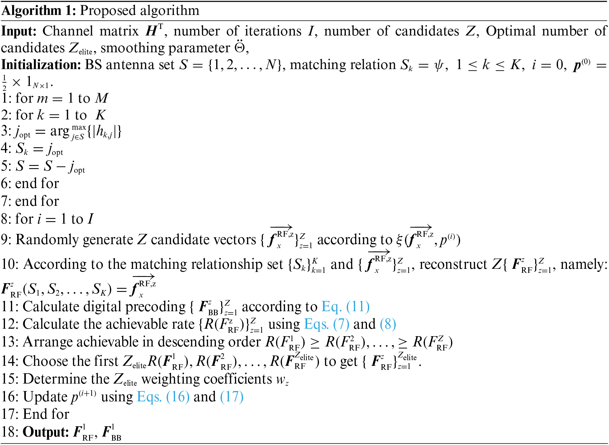
In order to reduce the number and precision of the hardware used, further research on hybrid precoding of partial connection structures has been carried out [17,18]. Reference [19] first proposed the hybrid precoding of switch and inverter based on machine learning adaptive cross entropy. The authors in [20–22] applied machine learning adaptive cross entropy to the hybrid precoding of lens array switch structure, and further analyzed the impact of important parameters based on the sum rate and energy efficiency of the hybrid precoding of the switch and inverter structure. Reference [23] proposes a precoding with an adaptive connection structure, which can better achieve beam gain, but still requires a higher-precision phase shifter (at least 6-bit accuracy) to achieve close to the optimal fully-digital precoding and lower precision such as 1-bit quantized adaptive connection structure is achievable and rate performance is severely reduced. In order to solve the problem of poor accessibility a rate performance of the 1-bit quantized phase shifter of the adaptive connection structure, this paper proposes a 1-bit quantized phase shift based on machine learning adaptive cross-entropy hybrid precoding. The adaptive connection structure that obtains the matching relationship between the RF chain and the base station antenna by maximizing the user's received signal power is more flexible than the fixed sub-connection. According to the probability distribution, the analog precoder is randomly generated, and the classic ZF precoding is used to obtain the corresponding digital precoder. The analog precoder is adaptively weighted according to the reach and rate. Then, the probability distribution of the simulated precoding is updated by reducing the cross entropy and adding a constant smoothing parameter, and repeating this way, a hybrid precoder with almost optimal performance and rate is finally obtained. Numerical simulations are performed to evaluate the effectiveness of the proposed scheme.
As shown in Fig. 1, consider the massive MIMO system of multi-user downlink, the base station deploys N antennas,
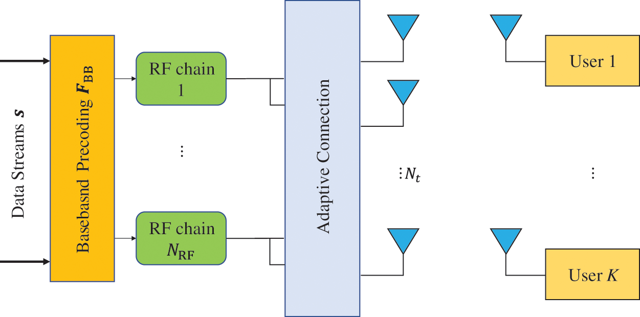
Figure 1: Proposed system model
The signal received by K users can be expressed as
Among them,
Among them, N is the number of antennas of the base station ULA antenna.
Here,
The analog precoding of the traditional low-precision phase shifter partial connection structure often fails to achieve the array gain of the millimeter wave large-dimensional antenna. Therefore, this article simulates the precoder adaptive connection and deploy adaptive connection network instead of fixed sub-connection switch and reverse vectorizer (equivalent to a phase shifter with 1-bit quantization). The same as the fixed sub-connection structure, the adaptive connection only requires N number of 1-bit quantized phase shifters,
Due to the special structure of the adaptive connection and the normal mode constraint of the elements in the analog precoder, the corresponding analog precoding
Indicates the connection relationship between all radio frequency chains and all antennas of the base station. Assuming that
The designed analog precoding
where
It can be seen that Eq. (7) is a non-convex optimization problem under the constraints of power constraints and adaptive connection structure. To maximize the total reachability and rate, that is, to maximize the SINR of the symbols received by each user, the
There are only M non-zero elements in
The constraint
Performing Eq. (10) once can match the
In the ACN-MLACE algorithm, since the phase shifter is quantized by 1 bit, the non-convex optimization problem of Eq. (7) has been transformed into a combinatorial optimization problem. How to obtain the
By initializing the probability distribution parameter
Put power constraints on it:
After that, the achievable sum rate
Here, the
There is also
Substituting Eq. (14) into Eq. (13), and then Eq. (13) finds the first derivative of its j-th probability element
Setting Eq. (15) equal to zero, the j-th element of the next probability distribution can be obtained
In order to ensure that the adaptive cross entropy optimization converges to the optimal solution to avoid local convergence, a constant smoothing parameter Ӫ can be further added between the current probability distribution and the next probability distribution.
Here
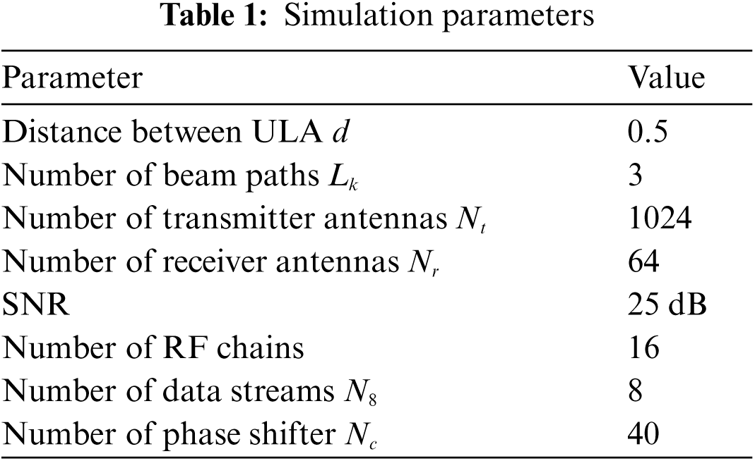
This section provides the simulation results and analysis. The proposed machine learning based precoding algorithm is compared with fully digital precoding, hybrid precoding of adaptive connection structure, and the conventional OMP precoding of structure. The combined precoding has the same lower hardware complexity and eliminates the
4.1 Achievable Sum Rate Comparison with Different Number of RF Chains and Data Streams with Fixed Antennas
Fig. 2 compares the achievable sum rate of the proposed algorithm, fully digital, and other algorithms vs. SNR for system configuration when the number of RF chains
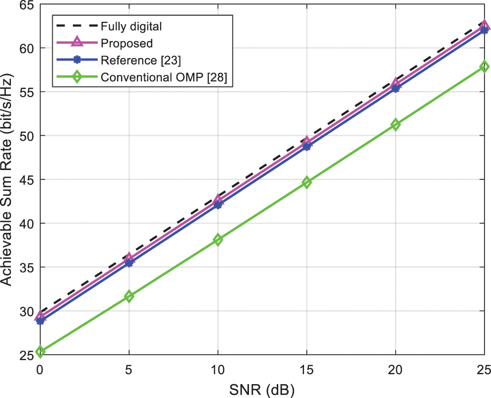
Figure 2: Comparison of achievable sum rate of algorithms vs. SNR when
Fig. 3 illustrates the achievable sum rate of the proposed algorithm, fully digital, and other algorithms vs. SNR for system configuration when the number of RF chains
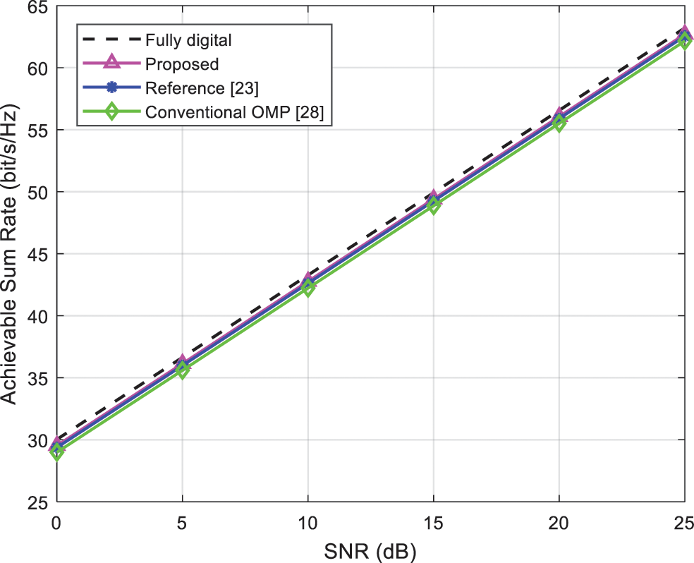
Figure 3: Comparison of achievable sum rate of algorithms vs. SNR when
4.2 Achievable Sum Rate Comparison with Different Number of Antennas with Fixed Number of RF Chains and Data Streams
Fig. 4 compares the achievable sum rate of the algorithms versus SNR when the number of transmitter antennas
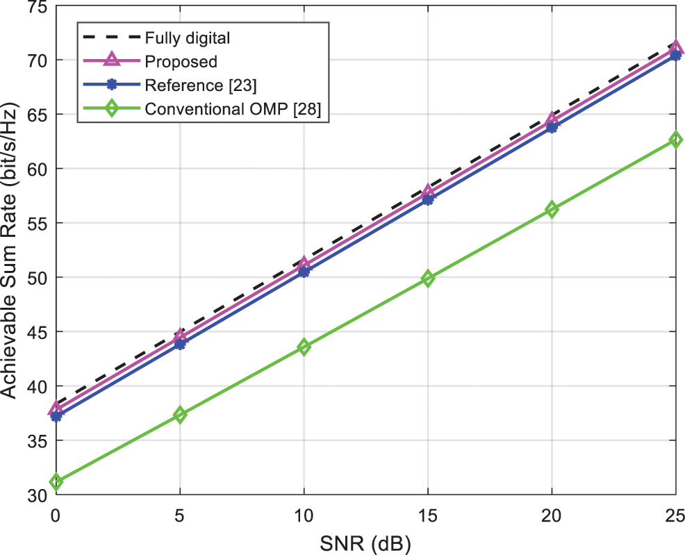
Figure 4: Comparison of achievable sum rate of algorithms vs. SNR when
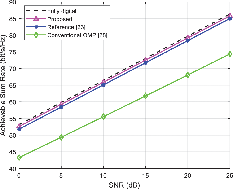
Figure 5: Comparison of achievable sum rate of algorithms vs. SNR when
Fig. 6 compares complexity of the algorithms with increasing number of antennas at the transmitters and
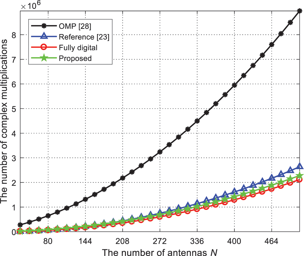
Figure 6: Complexity comparison of the algorithms vs. number of antennas
This paper proposes an adaptive connection network hybrid precoding with 1-bit quantization, and applies the adaptive algorithm based on machine learning to the adaptive connection structure hybrid precoding, which improves the 1-bit quantization phase shift of the adaptive connection structure. Under the same low hardware complexity, the proposed solution has a higher computational complexity than the switch and inverter hybrid precoding based on the fixed sub-connection of machine learning and the hybrid precoding based on the adaptive connection structure and achievable rate performance. Recently, highly efficient deep learning methods have been applied to hybrid precoding, and precoding with lower computational complexity and better spectral efficiency is worthy of further research.
Acknowledgement: Taif University Researchers Supporting Project Number (TURSP-2020/260), Taif University, Taif, Saudi Arabia.
Funding Statement: The authors received no specific funding for this study.
Conflicts of Interest: The authors declare that they have no conflicts of interest to report regarding the present study.
1. S. A. Busari, K. M. S. Huq, S. Mumtaz, L. Dai and J. Rodriguez, “Millimeter-wave massive MIMO communication for future wireless systems: A survey,” IEEE Communications Surveys & Tutorials, vol. 20, no. 2, pp. 836–869, 2018. [Google Scholar]
2. A. N. Uwaechia and N. M. Mahyuddin, “A comprehensive survey on millimeter wave communications for fifth-generation wireless networks: Feasibility and challenges,” IEEE Access, vol. 8, pp. 62367–62414, 2020. [Google Scholar]
3. A. Silva, S. Teodoro, R. Dinis and A. Gameiro, “Iterative frequency-domain detection for IA-precoded MC-cDMA systems,” IEEE Transactions on Communications, vol. 62, no. 4, pp. 1240–1248, 2014. [Google Scholar]
4. A. Silva, J. Assuncai, R. Dinis and A. Gameiro, “Performance evaluation of IB-dFE based strategies for SC-fDMA systems,” EURASIP Journal of Wireless Communications and Networking, vol. 13, pp. 1–10, 2013. [Google Scholar]
5. D. Castanheira, A. Silva, R. Dinis and A. Gameiro, “Efficient transmitter and receiver designs for SC-fDMA based heterogeneous networks,” IEEE Transactions on Communications, vol. 63, no. 7, pp. 2500–2510, 2015. [Google Scholar]
6. D. Castanheira, A. Silva and A. Gameiro, “Set optimization for efficient interference alignment in heterogeneous networks,” IEEE Transactions on Wireless Communications, vol. 13, no. 10, pp. 5648–5660, 2014. [Google Scholar]
7. O. E. Ayach, S. Rajagopal, S. Abu-Surra, Z. Pi and R. W. Heath, “Spatially sparse precoding in millimeter wave MIMO systems,” IEEE Transactions on Wireless Communications, vol. 13, no. 3, pp. 1499–1513, 2014. [Google Scholar]
8. D. Castanheira, S. Teodoro, R. Simoes, A. Silva and A. Gameiro, “Multi-user linear equalizer and precoder scheme for hybrid sub-connected wideband systems,” Electronics, vol. 8, no. 4, pp. 1–16, 2019. [Google Scholar]
9. Y. Wang and W. Zou, “Hybrid digital and analog precoding algorithm for millimeter wave MIMO systems,” in IEEE Wireless Communications and Networking Conf. (WCNC), Morocco, pp. 1–6, 2019. [Google Scholar]
10. W. Ni, X. Dong and W. Lu, “Near-optimal hybrid processing for massive MIMO systems via matrix decomposition,” IEEE Transactions on Signal Processing, vol. 65, no. 15, pp. 3922–3933, 2017. [Google Scholar]
11. Z. Wang, M. Li, Q. Liu and A. L. Swindlehurst, “Hybrid precoder and combiner design with low-resolution phase shifters in mmwave MIMO systems,” IEEE Journal of Selected Topics in Signal Processing, vol. 12, no. 2, pp. 256–269, 2018. [Google Scholar]
12. R. Zhang, W. Zhou, Y. Wang and M. Cui, “Hysbrid precoder and combiner design with finite resolution PSs for mmWave MIMO systems,” China Communications, vol. 16, no. 2, pp. 95–104, 2019. [Google Scholar]
13. F. Dong, W. Wang and Z. Wei, “Low-complexity hybrid precoding for multi-user mmwave systems with low-resolution phase shifters,” IEEE Transactions on Vehicular Technology, vol. 68, no. 10, pp. 9774–9784, 2019. [Google Scholar]
14. L. Liang, W. Xu and X. Dong, “Low-complexity hybrid precoding in massive multiuser MIMO systems,” IEEE Wireless Communications Letters, vol. 3, no. 6, pp. 653–656, 2014. [Google Scholar]
15. W. Zhang, Z. Wei and J. Wu, “UAV beam alignment for highly mobile millimeter wave communications,” IEEE Transactions on Vehicular Technology, vol. 69, no. 8, pp. 8577–8585, 2020. [Google Scholar]
16. Y. Ren, Y. Wang and G. Xu, “Two-stage hybrid precoding for massive MIMO systems,” in IEEE 22nd Int. Conf. on Telecommunications (ICT), Australia, pp. 294–297, 2015. [Google Scholar]
17. R. M. Rial, C. Rusu, A. Alkhateeb, N. G. Prelcic and R. W. Heath, “Channel estimation and hybrid combining for mmwave: Phase shifters or switches?,” in Information Theory and Applications Workshop, USA, pp. 90–97, 2015. [Google Scholar]
18. T. Mir, M. Z. Siddiqi, U. Mir, R. Mackenzie and M. Hao, “Machine learning inspired hybrid precoding for wideband millimeter-wave massive MIMO systems,” IEEE Access, vol. 7, pp. 62852–62864, 2019. [Google Scholar]
19. X. Gao, L. Dai, Y. Sun, S. Han and I. C. Lin, “Machine learning inspired energy-efficient hybrid precoding for mmwave massive MIMO systems,” in IEEE Int. Conf. on Communications (ICC), Paris, France, pp. 1–6, 2017. [Google Scholar]
20. H. Huang, Y. Song, J. Yang, G. Gui and F. Adachi, “Deep-learning based millimeter-wave massive MIMO for hybrid precoding,” IEEE Transactions on Vehicular Technology, vol. 68, no. 3, pp. 3027–3032, 2019. [Google Scholar]
21. T. Ding, Y. Zhao, L. Li, D. Hu and L. Zhang, “Hybrid precoding for beamspace MIMO systems with Sub-connected switches: A machine learning approach,” IEEE Access, vol. 7, pp. 143273–143281, 2019. [Google Scholar]
22. M. Tian, J. Zhang, Y. Zhou, L. Yuan, J. Yang et al., “Switch and inverter based hybrid precoding algorithm for mmwave massive MIMO systems: Analysis on sum-rate and energy-efficiency,” IEEE Access, vol. 7, pp. 49448–49455, 2019. [Google Scholar]
23. X. Zhu, Z. Wang and L. Dai, “Adaptive hybrid precoding for multiuser massive MIMO,” IEEE Communications Letters, vol. 20, no. 4, pp. 776–779, 2016. [Google Scholar]
24. L. Y. Deng, “The cross-entropy method: A unified approach to combinational optimization, monte-carlo simulation, and machine learning,” Technometrics, vol. 48, no. 1, pp. 147–148, 2012. [Google Scholar]
25. A. Costa, O. D. Jones and D. Kroess, “Convergence properties of the cross-entropy method for discrete optimization,” Operation Research Letters, vol. 35, no. 5, pp. 573–580, 2007. [Google Scholar]
26. Z. Wu and M. Kolonko, “Asymptotic properties of a generalized cross-entropy optimization algorithm,” IEEE Transactions on Evolutionary Computation, vol. 18, no. 5, pp. 658–673, 2014. [Google Scholar]
27. A. M. Elbir and A. K. Papazafeiropoulos, “Hybrid precoding for multiuser millimeter wave massive MIMO systems: A deep learning approach,” IEEE Transactions on Vehicular Technology, vol. 69, no. 1, pp. 552–563, 2020. [Google Scholar]
28. T. S. Rappaport, S. Sun, R. Mayzus, H. Zhao, Y. Azar et al., “Millimeter wave mobile communication for 5G cellular: It will work!,” IEEE Access, vol. 1, pp. 335–349, 2013. [Google Scholar]
 | This work is licensed under a Creative Commons Attribution 4.0 International License, which permits unrestricted use, distribution, and reproduction in any medium, provided the original work is properly cited. |