DOI:10.32604/cmc.2022.020091
| Computers, Materials & Continua DOI:10.32604/cmc.2022.020091 | |
| Article |
New 5G Kaiser-Based Windowing to Reduce Out of Band Emission
1Faculty of Electrical and Electronic Engineering, Universiti Tun Hussein Onn Malaysia, Batu Pahat, 86400, Johor, Malaysia
2School of Engineering, Arts, Science and Technology, University of Suffolk, IP4 1QJ, UK
3College of Computer Science and Information Technology, University of Anbar, Anbar, 31001, Iraq
4Electrical Engineering and Computer Science Department, University of Tennessee, Knoxville, TN, 37901, USA
*Corresponding Author: Laith Al-Jobouri. Email: L.Al-Jobouri@uos.ac.uk
Received: 08 May 2021; Accepted: 21 June 2021
Abstract: OFDM based waveforms are considered as the main part of the latest cellular communications standard (namely 5G). Many inherited problems from the OFDM-Based LTE are still under investigation. Getting rid of the out of band emissions is one of these problems. Ensuring low out of band emission (OOBE) is deemed as one of the most critical challenges to support development of future technologies such as 6G and beyond. Universal Filtered Multi Carrier (UFMC) has been considered as one of the candidate waveforms for the 5G communications due to its robustness against Inter Carrier Interference (ICI) and the Inter Symbol Interference (ISI). It is also a preferred option because it is the most appropriate for low latency scenarios. In this paper, a novel approach is proposed that makes use of modified Kaiser-Bessel filter-based pulse windowing instead of standard Dolph-Chebyshev filter for UFMC based waveform. The aim of proposing the new approach is to enable the reduction of spectral leakage into nearby sub-bands. A comprehensive study for the modified Kaiser-Bessel filters is performed and the results are presented in terms of several Key Performance Indicators (KPIs). Based on the results of the simulation, the UFMC Kaiser-Hankel window demonstrated lower sidebands and better power spectral density, when compared with the traditional Orthogonal frequency-division multiplexing (OFDM) and UFMC as well as the normal UFMC Kaiser window. In addition, the real test for the kaiser window with 5G waveform is lower OOBE than conventional 5G waveform (CP-OFDM and UFMC). The OOBE reduction of 31% of the Kaiser vs. the Dolph-Chebyshev filter, 68% of Kaiser Hankel over the Dolph-Chebyshev, and 20% of Kaiser Hankel over Kaiser filter have been reported in this paper. The Power Spectral Density has been improved accordingly.
Keywords: 5G; Kaiser-Bessel filter; OFDM; UFMC; waveform
There is an increasing demand for bandwidth by the new services and applications like virtual reality (VR), Augmented Reality (AR), ultra High Definition (HD) Video transmission and 3-Dimensions (3D) games. For this reason, researchers are putting in more efforts towards the development of superior technologies for 5G and beyond wireless communication systems. Phase-1 of (5G) is already achieved through the 3GPP Release-15 [1] and its deployment is already going on rapidly around the world. Presently, the efficiency of the OFDM technique has resulted in its extensive use in wireless communications and several new communication systems. Nevertheless, the OFDM is accompanied by some limitations such as ICI and high Peak to Average Power Ratio (PAPR). The ISI occurs in OFDM, if the delay in channel distribution is higher than the Cyclic Prefix (CP) length [2]. Therefore, new techniques for 5G communication systems have been introduced to address the aforementioned limitations. An example of such techniques is the UFMC, which is a waveform technique used in the cellular world of 5G [3]. With this waveform, a number of subcarriers are grouped into sub-bands, such that the cyclic prefix is removed and the out-of-band emissions diminishes. Presently, the use of Dolph-Chebyshev filters alongside other filter optimization techniques are employed in the implementation of the UFMC [4]. It has been observed that spectrum leakage occurs as a result of the flatness of the side-lobe fall rate of Dolph-Chebyshev filter, which causes out-of-band emissions. To this end, an attempt was made to address the problem by proposing the use of Bohman filter, which allows the realization of the (−24 dB/octave) sidelobe fall rate as compared to (0 dB/octave) using Dolph-Chebyshev filter [5]. With the existing solutions for the side-lobe suppression, sometimes spectral efficiency is lost or the performance of Bit Error Rate (BER) degrades [3]. These are regarded as the limitations of such solutions available in the literature.
Another problem associated with the state-of-the-art solutions is higher PAPR, which is an inherent feature of the OFDM based waveforms. This implies that the benefits of the sidelobe suppression are deceptive in the sense that after the spectral side-lobes pass the high peak power signals through the high-power amplifiers (HPA), they re-grow. In signals that are progressively modulated, huge changes in signals can lead to wider modulation sidebands or spectral re-growth; this is referred to as in-band distortions. For signals to be properly received at the receivers, adequate power is used to transmit the signal by all the radio communication transmitters using HPAs. The HPAs are often located close to the region of saturation so that they can achieve high levels of efficiency, but this causes the introduction of out-of-band spectral regrowth [6]. Another cause of huge change in signals, is a rapid sidelobe rate reduction, and this in turn causes the introduction of in-band distortions by the HPAs, thereby indirectly resulting in higher PAPR [7]. The problem of spectral regrowth is also caused by the Bohman filter due to rapid decline in sidelobe rate of (−24 dB/octave), and this in turn indirectly causes higher PAPR. Thus, it is important to find ways through which this problem of PAPR can be solved without causing an increase in out-of-band emissions as discussed in [8,9].
The main contributions of this study can be summarized as:
• Suggesting windowing techniques for increasing the spectral efficiency of the signal in 5G and 6G waveform.
• Proposing a new 5G waveform window method by using Kaiser Hankel window to increase the spectral efficiency of the 5G signal.
• Two variants of 5G waveform can be identified therein, by pairing either CP-OFDM or UFMC with either windowing or filtering at the modulator. Both CP-OFDM and UFMC are covered as special cases; they can be described as filtered CP-OFDM and filtered UFMC, respectively.
The rest of the paper is organised to provide a brief review of the related work in Section 2. The UFMC architecture waveform and architectures of 5G are briefly explained in Section 3. The proposed windowing model is explained in Section 4, where as the window transfer design is shown in Section 5. Simulation results are discussed in Section 6, whereas the experimental results are shown in Section 7. Finally, the conclusions and future work are presented in Section 8.
A lot of work has been done to improve the 5G waveforms and reduce the out of band emissions (OOBE) and many of these recent works have been surveyed in [3]. Generally, we can divide these techniques into three types: the techniques represented by Frequency domain, by precoding matrices, and by symbol mapping [10–22]. Adaptive symbol transition (AST) [10] is considered one of the time domain techniques where they solve the problem of OOBE by inserting between two-time blocks, but they suffer from spectrum efficiency loss and data-dependent design [10]. Many filtering techniques are used where some filters are inserted in the time domain (as we will see shortly) but many of them are inefficient in terms of the extension of the symbol which causes spectrum efficiency loss [11]. Another time domain technique includes using windowing where some window function applied in time domain [13,14] but they suffer the same limitations like the filtering techniques. The other type of techniques are the ones represented by the precoding matrices [12,15–18]. In [12], the authors suggest using Guard Subcarriers (GS) where they reserve subcarriers on the edges with zero input. Despite being a good solution, it still suffers from less spectral efficiency. Carrier Cancellation (CC) in [15] is the same as [12] except that its principle is to reserve a subcarrier on the edges with non-zero input and it also suffers from spectrum efficiency loss and data-dependent design. Subcarrier weighting (SW) in [16] is also considered as a precoding matrix technique to improve the OFDM and 5G Waveforms where different subcarriers assigned with different coefficients and it has data dependant design issue [16]. A precoding matrix with different purposes for different approaches is used in [17,18] and suffers from loss in spectral efficiency.
Some Symbol mapping techniques include [19–22]. Multiple choice sequence (MCS) is suggested in [19] where they use multipath streams for selection and have large overhead that causes the spectral efficiency to drop. Constellation Expansion (CE) on the other hand, can be used to improve the OOBE performance but it suffers from the need to enlarge the transmit power and reduce the (BER) performance [20]. N-Continuous OFDM structure and out-of-band (OOB) reduction methods that use multipath channels were suggested in [21,22] where continuous signals and derivatives of signals are used. The only limitation in such design is the iteration decoder that adds large overhead to the system [23–27].
UFMC is a technique that involves the filtration of sub-carriers prior to transmission and reception so that the ISI and ICI can be eliminated. UFMC is a modulation technique that can be considered as a generalized Filter Bank Multi-Carrier technique (FBMC) [24–29] and filtered OFDM. More so, it is a multicarrier modulation technique with orthogonal sub-carriers that enhance the mitigation of the problem of orthogonality loss at the side of the receiver. In FBMC, each subcarrier is filtered, whereas in OFDM filtering is applied in a single shot to the whole multicarrier band [30,31]. There are several advantages which the FBMC possesses, including lower ICI, in case of jitter or frequency offsets [32]. However, the use of filter banks in FBMC causes the computational complexity of the signal to escalate [32]. In filtered OFDM, the total band is filtered. Hence, the filter has a bandwidth that is larger than that of FBMC, and a length that is lesser than that of FBMC. The filtration in UFMC subsets is applied on the entire band, rather than total band or single sub carriers [3,32].
Fig. 1 below shows the general structure of the UFMC transmitter with B sub-bands. The UFMC transmitter in our work is designed as mentioned in [33]. UFMC ith sub-module, where
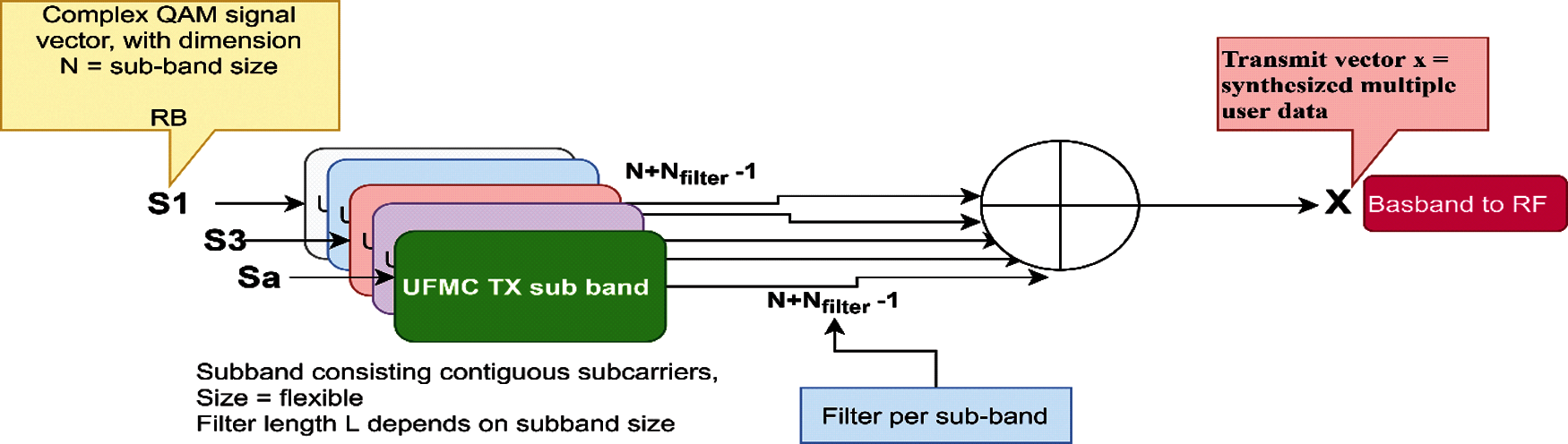
Figure 1: General UFMC transmitter structure
Fig. 1 shows that the synthesis of transmit vector X involves the combination of single sub-band signals. In downlink (DL), the transported data is delivered to multiple users on single sub-modules over the all available frequency bands, whereas in uplink (UL), the user uses the assigned frequency portion. The construction of a single sub-band signal is illustrated in Fig. 2.
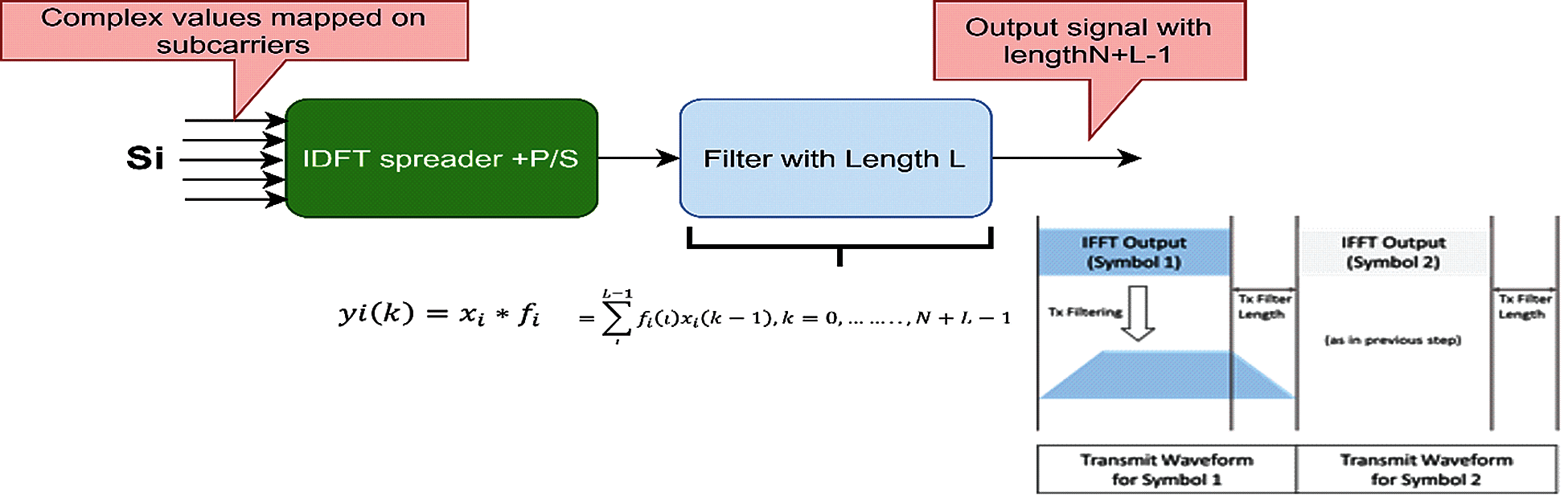
Figure 2: UFMC transmitter sub module
The use of Inverse Discrete Fourier Transform (IDFT) spreader leads to the change of the Ni complex QAM symbol to time domain and then subband filtering is carried out. For a given multicarrier symbol, the time-domain transmit vector is the superposition of the sub band wise filtered components as given in Eq. (1):
where Vi indicates dimension N times, Si denotes the significant columns of the Inverse Fast Fourier Transform (IFFT) matrix as per the position of sub-band; Fi is a Toeplitz matrix whose dimension is (N + Nfilter−1) time N and it consists of the Finite Impulse Response (FIR) that enables the convolution. The rewritten signal, without the summation is defined as in Eqs. (2)–(4):
With this type of wise piling of filter matrices enabled, an IDFT matrix is generated and all the data symbols are combined into a single column. This results into:
Tab. 1 provides a list of the designed parameters required. Here, B is dependent on the UFMC transmitter spectral settings. In an event that the application of the system is made to the fragmented spectrum, the selection of B should be done based on the available number of spectral sub-bands. Alternatively, for the streamlining of the whole system, and regulation of spectral characteristics at a granular level, the single sub-band can be divided into minute chunks of same range in each sub-band, and these particular spectral chunks are called as Physical Resource Blocks (PRB), as in the LTE [34–37]. There are different options available for the selection of the filter characteristics depending on the window selection and the controllability characteristics of a filter with regards to attenuation of side lobe and main lobe width that determines its selection. The values for each of these parameters used in our experiments will be mentioned in the simulation results section.
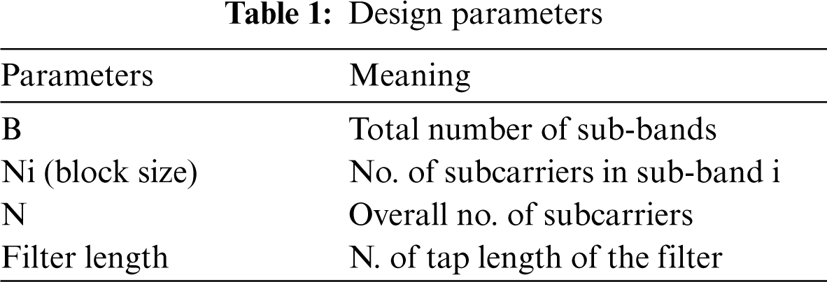
Fig. 3 shows the UFMC receiver block diagram. In UFMC signal reception, processing is done on the elements for simplicity, which deals with blocks like channel estimation/equalization, error correction. Based on Fig. 3 and Eq. (6), Y is the received signal vector that has passed through the channel, with Toeplitz structure by convolution matrix H, including the noise n:
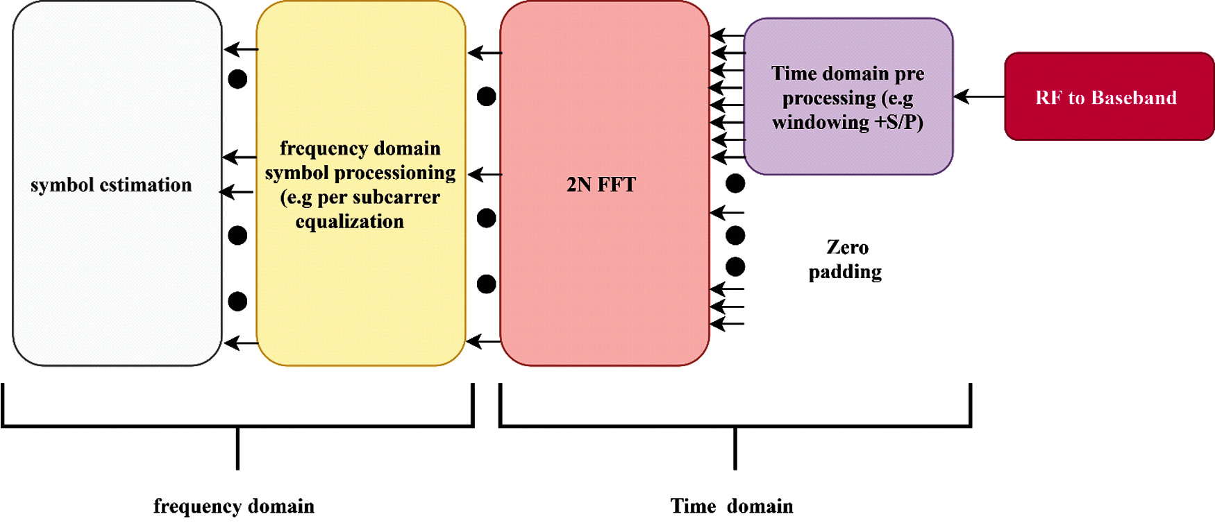
Figure 3: UFMC receiver block diagram
The output symbol vectors are transmitted by each Rx sub-module of UFMC to the respective sub-bands along with alterations. In Up-Link (UL), data is transmitted using the Rx sub-modules, so that the whole frequency range can be covered, while in Down Link (DL) the receiver serves as a component of the user device. Active single sub modules or the PRBs are the carriers of data, and they also control messages relevant to an assigned user. There is a wide range of methods that can be used in designing UFMC, and in the case of an ideal linear receiver under an AWGN channel, consideration is given to Zero Forcing filter (ZF) and Minimum Mean Square Error (MMSE) and they can be given as in Eqs. (7) and (8):
where, denotes the Moore-Penrose-Inverse of a matrix, the Hermitian transpose is denoted by Eq. (8), is the noise variance and represents the identity matrix. The operation basically combines the inverse filtering and DFT sequentially. Due to the fact that the UFMC needs two times the FFT size for decoding, the computational complexity is doubled at the receiver. Nevertheless, recent advancement in processors allows the use of multi cores, which in turn prevents latency and computational complexity.
4 Proposed UFMC-Kaiser Bassel Window Model
In order to address the limitations of the Dolph-Chebyshev, some researchers have used other alternatives such as the Bohman Filter [5,36]. In the Dolph-Chebyshev window, FIR-coefficients are applied, and they are parameterized based on the side-lobe attenuation [4]. This side lobe attenuation for any sort of main lobe width is maximized by the Dolph-Chebyshev. The popular Chebyshev polynomials that were first introduced by Nilchian et al. [37] are the constituents of the Dolph-Chebyshev function, and they are used in solving the design problem of optimizing the directional characteristics of a radio antenna. The optimal Dolph-Chebyshev window transform is expressed as given in the following Eq. (9):
where:
Here, the compounding window times samples W(n) are obtained by performing a DFT on the samples W(n), which are scaled for unity peak amplitude. The parameter denotes the log of the ratio of main lobe level to side lobe level. Therefore, a value of equal to 3.0 represents side lobes 3.0 decades down from the main lobe, or side lobes 60.0 dB below the main lobe. The sign of successive transform samples is alternated by the-I, thereby reflecting the shifted origin in the time domain. And denotes the side-lobe attenuation's length. The parameter represents the logarithmic ratio of main lobe level to side-lobe level, and the Dolph-Chebyshev window can be controlled when the parameter is changed. The characteristics in frequency domain and time domain for ideal settings with filter length is shown in Fig. 4 with side-lobe attenuation of 40 and 60 dB.
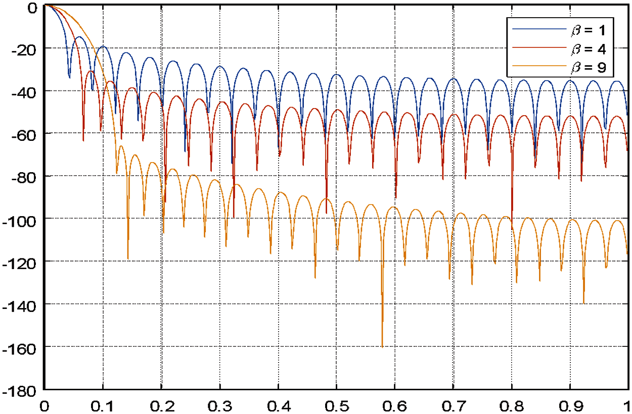
Figure 4: Kaiser window control the OOBE with increase beta values
The use of Kaiser-Bessel window and FIR filter is employed in the current study so as to enable the control of spectral leakage, and to solve the problem of Spectral concentration. In addition, the use of Hankel function is employed in order to gain more control of OOBE. The Discrete Prolate Spheroidal Sequence (DPSS) window based upon Bessel functions are popularly referred to as the Kaiser window (or Kaiser-Bessel window), and are compared with Dolph-Chebyshev window.
In the case of a sample with N points, the following Eq. (11) defines the Kaiser Windowing function w with parameter alpha. The Eqs. (11) and (12) below is used in computing the coefficients of a Kaiser window:
where
Based on Fig. 5, Kaiser-Bessel window performs better than the Dolph-Chebyshev in the frequency domain. From Fig. 5, the Fourier transform's side-lobe attenuation parameter is affected by the input in the Kaiser-Bessel window. By means of the β parameter, the exchange of window between the main lobe width and side-lobe level is continuously controlled due to the kaiser window using modified the discrete prolate spheroidal or Slepian sequences derived from the following time-frequency concentration problem. When the values are larger with lower side-lobe levels, a wider main lobe is provided, while lesser side-lobes lead to minimize channel crosstalk. The figure below shows that the Kaiser with Hankel demonstrated better performance than that of the Basell function. The values for the Kaiser-Bessel window as well as the side-lobe attenuation for the kaiser window filter is chosen to be 1, 4, and 9, because they were found to be the best value by an iterative process.
On the other hand, Bessel function shown in Fig. 4, is considered one of a class of the unique functions associated with the hypergeometric functions that arise as solutions of Bessel's equation. Standard solutions are known as the Bessel functions of the first and second kinds, Jn(z) and Yn(z), respectively, the modified Bessel functions of the first and second kinds, in z and Kn(z), respectively, and the Hankel functions, Hn(1)(z) and Hn(2)(z), also known as the Bessel functions of the third kind as shown in the Fig. 10. The Hankel function is also considered as one of a class of special functions that are related to the hypergeometric functions that arise as solutions of Bessel's equation; also known as Bessel functions of the third kind. They are defined by:
The Fourier transform of the Kaiser Hankel window Wk(t) from [38] is modified to be as in Eq. (16). Here, t is the time for the continuous signal. The use of Hankel with Kaiser enhances the suitability of the control and OOBE with the system as illustrated in Fig. 10. Also, for exp., the windowing method's impact on the different communication systems prioritizes by decreasing the number of windows tapes the difficulty and latency can be decreased. Therefore, once the OOBE is that, it would be simple to coexist and improve the PSD and trigger Release 15 and 16 specifications in the 3GPP.
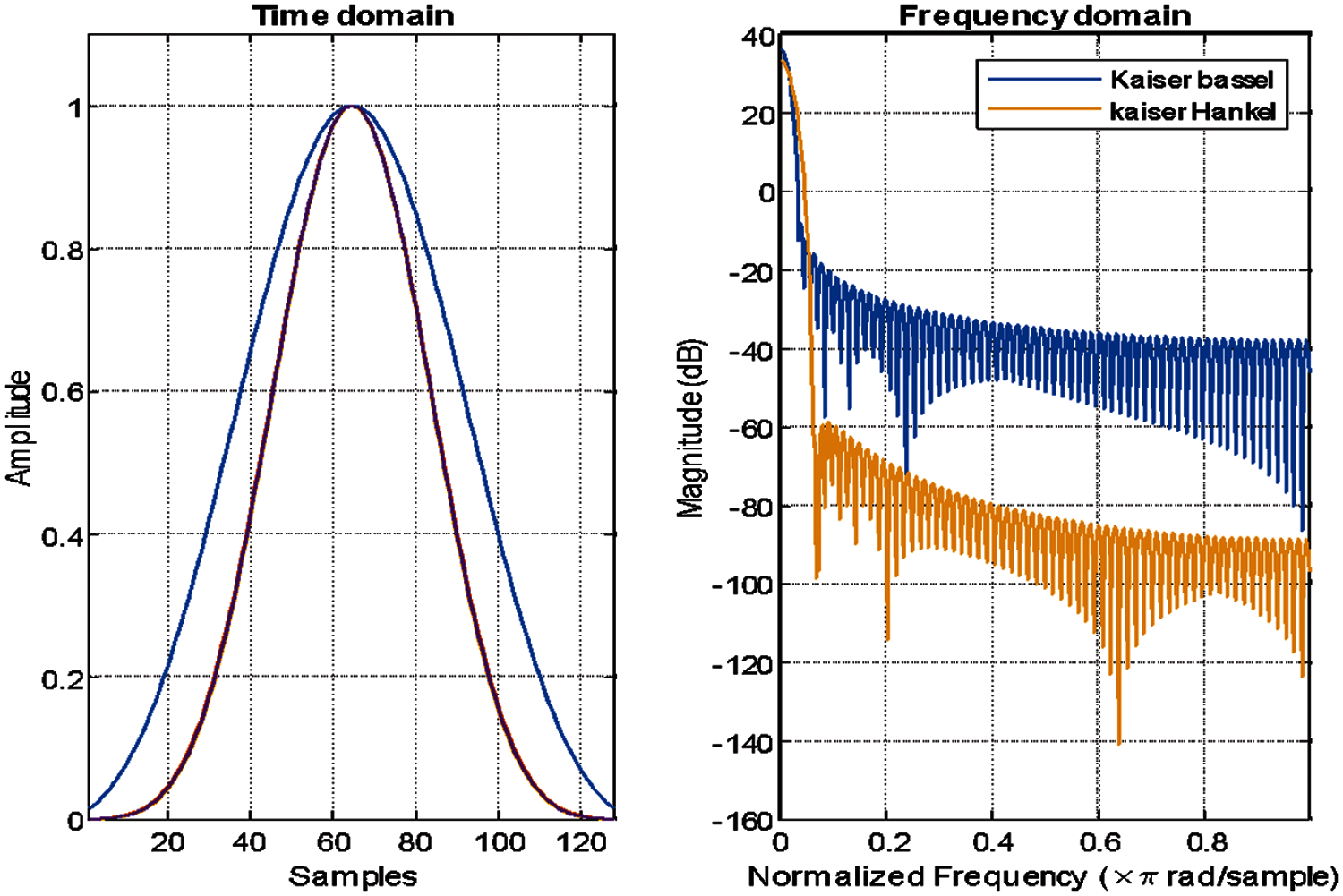
Figure 5: Kaiser-Bessel filter and Kaiser Hankel characteristics in time domain and frequency domain (=2.7, filter length: 20)
The sequence shown in Fig. 10 below is followed in this study. The initial stage involves the use of the MATLAB program to assess the performance of the Dolph-Chebyshev window with a UFMC 5G waveform. With UFMC, a better localization is provided within the frequency domain, and it also provides robustness against time frequency offsets compared to CP-OFDM. In addition, in comparison to sub-carrier-wise filtering, the shorter filter lengths demonstrate better suitability low-latency applications. However, the OOBE suppression of the shorter filters is limited. The second step involves the simulation of UFMC with Kaiser window in the same parameter that is used with The Dolph-Chebyshev window-UFMC as well as the Kaiser Hankel-UFMC system. All the tests for the system were done under the main KPI (PSD, BER, ACPR, complexity and PAPR).
The use of MATLAB software was employed in the simulation of the UFMC system. The software was used alongside both Dolph-Chebyshev filters and Kaiser-Bessel windows. Tab. 2 below contains the basic input parameters that were used in simulating the system. There is a linear correlation between the length of filter and the ratio of the number of sub-carriers to the no. of sub-bands, and the filter peak-to-bottom gain-ratio (PBGR) in one sub-band as mentioned in [39–42]. The assumption in this study is that the non-frequency selectivity across the sub-carriers implies that PBGR is assumed to be zero. So, the filter length is defined as ratio of total number of sub-carriers to UFMC block size, which in this case is 16 (or 256/16).
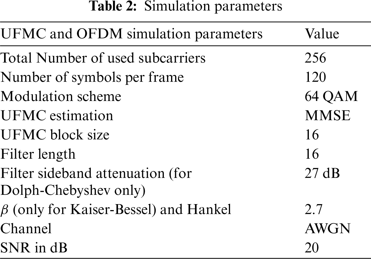
Fig. 6 shows the UFMC filter characteristics that have been simulated in time domain for both the Dolph-Chebyshev filter and the Kaiser-Bessel filter, alongside Kaiser-Hankel filter with rectangular filter of OFDM. The filter's impulse responses are indicative of the narrow nature of the UFMC filter pass band, which is narrower than the OFDM filter. This implies that in the UFMC technique, there is better utilization of the spectrum, especially for the fragmented spectrum applications. Fig. 6 shows the UFMC filter characteristics that have been filtered in frequency domain for both Dolph-Chebyshev filter and Kaiser-Bessel filter. In comparison to the Dolph-Chebyshev filter which offers (0 dB/octave), asymptotic roll-off of (6 dB/octave) is provided by the Kaiser-Bessel window. Fig. 6 show that the UFMC filter sideband attenuation with Kaiser-Hankel outperforms both the OFDM and Kaiser Bessel of the UFMC (Dolph-Chebyshev).
6.2 Power Spectral Density (PSD) Analysis
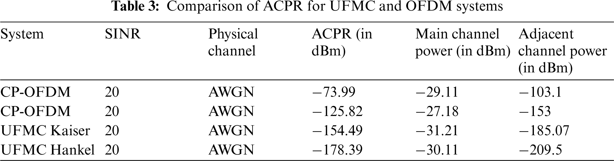
Fig. 7, shows the PSD analysis for UFMC with Kaiser-Bessel, Dolph-Chebyshev, and Kaiser-Hankel filters and OFDM systems with AWGN. During the simulations, the use of AWGN with SNR = 30 dB and MMSE estimation are employed at the receiver. As can be seen in Fig. 7, the result of the Adjacent Channel Power Ratio (ACPR) of the original CP-OFDM signal starts at −73.99 dBm, whereas the ACPR of the CP-OFDM signal using the Dolph-Chebyshev windowing is 125.82 dBm, thereby the improvement in the PSD performance for the CP-OFDM Dolph-Chebysheva is 51.83 dBm as mention in the Tab. 3. Similarly, the presents of the PSD shapes of the UFMC with Kaiser-Bessel windowing signal is better performance reduction compare with Dolph-Chebyshev and the enhancement in the PSD performance is −28.69 dBm. The superior PSD shapes of the UFMC with Kaiser-Hankel windowing compare with Kaiser-Bessel windowing and Dolph-Chebyshev, the achievement reduction of the OOBE under KPI ACPR is 23.9, 52.75 dBm respectively. This advantage of Kaiser-Hankel windowing is because the Kaiser-Hankel windowing suppresses the OOBE leakage and have a good time localization low discontinuity of the signal.
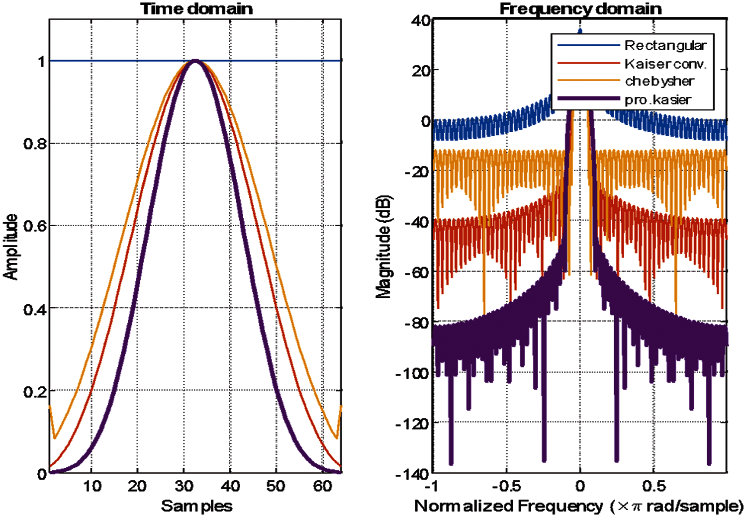
Figure 6: Time-frequency domain-UFMC with windows, kaiser conventional, chebyshev and proposed kaiser and rectangular CP-OFDM
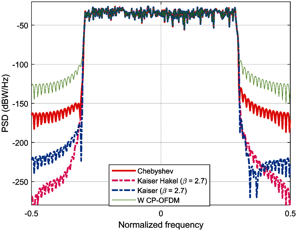
Figure 7: PSD analysis of UFMC-Kaiser, Dolph-Chebyshev, hankel and OFDM with AWGN SNR = 30 dB
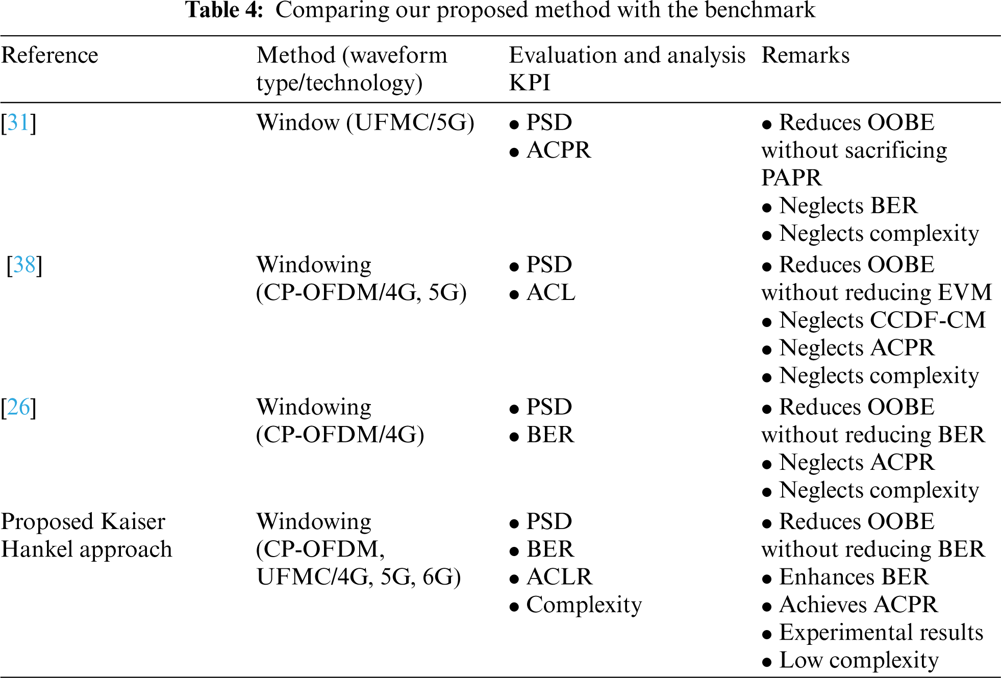
Tab. 4 shows that the Kaiser Hakel windowing waveform has been applied to the F-OFDM and UFMC to reduce the OOBE of this waveform. Subsequently, the UFMC waveform has not been proposed and evaluated under Kaiser Hankel windowing. Hence, this study indicates that the Kaiser Hankel windowing proposed can be used to reduce without an increase the complexity of the system and without degradation in BER.
With regards to BER performance, Fig. 8 presents the performance of the 64-QAM based Kaiser, Chebyshev, hankel UFMC signal. Based on Fig. 8, the BER performance demonstrated by the conventional CP-OFDM shows that it requires more power, whereas, improved BER was demonstrated by Chebyshev, Kaiser, and Kaiser–Hankel UFMC signals. However, when B = 2.7, the BER of the Kaiser improved slightly. This results from the fact that the subbands in the CP-OFDM are not protected from each other's interference.
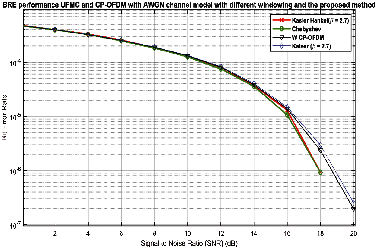
Figure 8: BER performance evaluation of 64QAM UFMC based Chebyshev, Kaiser, Kaiser–Hankel windows compared with the traditional 64QAM CP–OFDM
The criteria of the 5G network is that it will be computationally fast, in order to expand the lifespan of low-power devices. The computational complexity is explored and contrasted to OFDM with different windowing waveform choices, such as UFMC. A crucial dimension of computational complexity depends on several actual multiplications per burst for each windowing waveform. The most apparent result from the study is that two things should be influenced as the complexity is reduced; low latency communications and low energy usage of both the transmitter and the receiver, which is an integral 5G requirement. The UFMC waveform can be parameterized to two extremes: to minimize the out-of-band radiation, one continuous CP-OFDM signal is routed with one filter at one end. According to Eq. (17), the complexity of the CP-OFDM is calculate depend on the number of FFT/IFFT that uses in the system and represented
where the
where Lw is the length of window, to be fair in the comparison between the different windowing with waveform according to the complexity, windowing length depends on the windowing order, meaning that L is the windowing length and the windowing order is one less than the length (L − 1). When increasing the order of the window means that an increase in the length of the window as a result increases the complexity of the system. According to Tab. 2 the simulation parameters, the complexity of the CP-OFDM less than the UFMC. Moreover, the Hankel_UFMC is less complex than the Kaiser and conventional UFMC If we take into account the value of OOBE reduction. When we need a UFMC waveform that achieves the same OOBE performance, the Hankel UFMC, should increase the value of Chvechiveshy filter order if used the conventional UFMC mean that increases the complexity of the system and increases the value of the beta with Kaiser windowing [43].
In this section, we explain the real test for the conventional CP-OFDM and UFMC using kaiser windowing by using Tektronix tools and NI devices. Arbitrary Waveforms were generated using the AWG7122C signal generator by using conventional CP-OFDM with Raised cosine pulse shaping for the channel one and using kaiser windowing for channel 2. Real Time spectrum analyzer 6106A was used to analyze and show the OOBE by frequency mask trigger and Time DPX for the range (9 kHz–6.2 GHz/40 MHz). For the NI tool, USRP-2921 devices and SDR nodes were used, these devices work in 2.4–2.5 GHz and 4.9–5.9 GHz frequency bands and with the use of USRP 210.
In our waveform studies, we first create a simulation environment by using MATLAB with Tektronix tools (adding MATLAB file in Arbitrary Waveform Generators AWG7122C to change the windowing type) as a simulation tool and compute numerical performance results. For OFDM and UFMC, we followed the same methodology and observed power spectral density graphs to analyze sidelobe suppression performance. Fig. 9 shows a sidelobe performance of CP-OFDM before used kaiser window. These results show the large improvement in the spectral confinement performance that can be achieved by both CP-OFDM and UFMC and that help to succeed the Dynamic time domain coexistence between 4G LTE and 5G is feasible as shown in the Fig. 10. In addition, more suitable for coexistence for flexible Reframing.
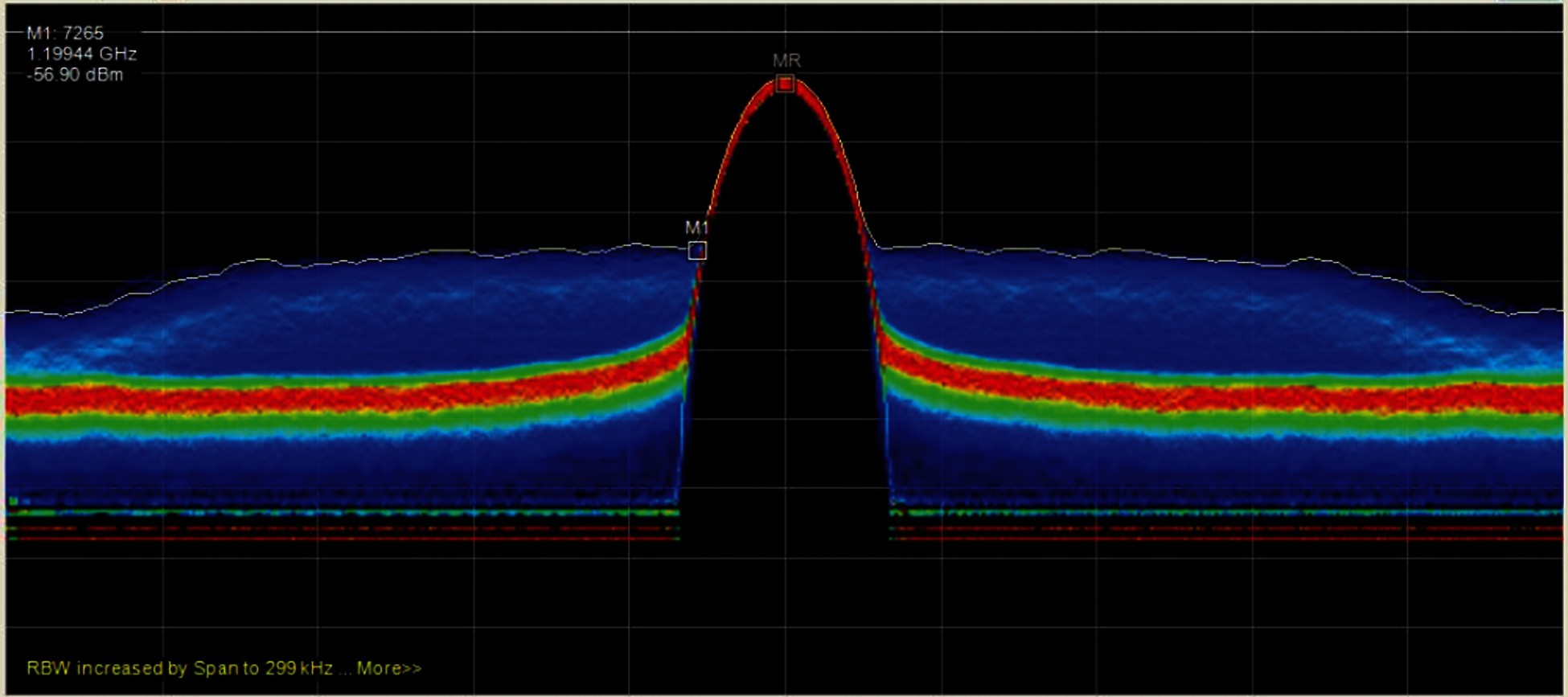
Figure 9: A sidelobe performance of CP-OFDM before used kaiser window
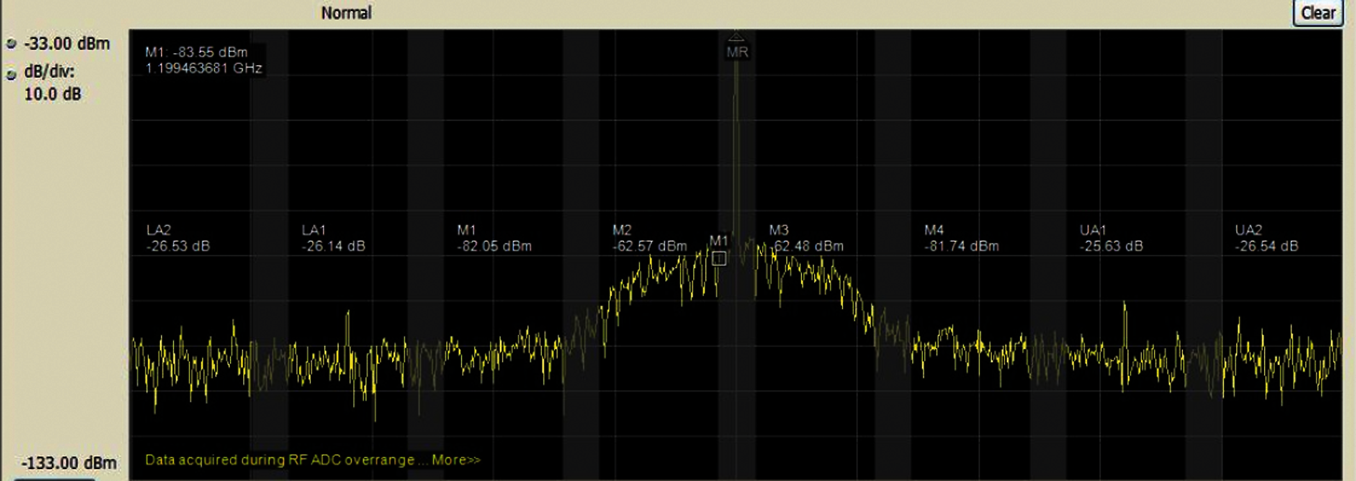
Figure 10: The RRC CP-OFDM windowing spectrum
The Kaiser windowing CP-OFDM shows that with the spectrally confined waveform, the spectrum utilization in 10 MHz carrier bandwidth can be increased significantly, from 90% in CP-OFDM to 98% as shown in Fig. 11. The tests for real windowing with 5G waveform show that with the spectrally confined waveform, the spectrum utilization can be increased significantly by reducing the OOBE. In addition, it could use the coexistence with the incumbent system like 4G without interference specifically when using the 5G waveform non-standalone as shown in the Fig. 11. The limitations of this study should test the proposed windowing with different numerology and channel modes.
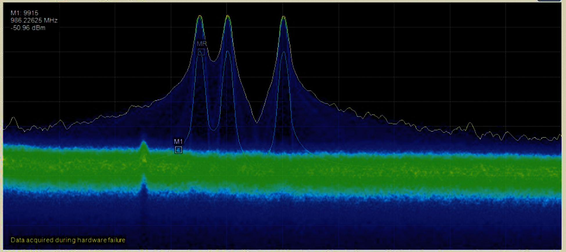
Figure 11: 4G and 5G green coexistence
In this study, several filters have been discussed and their performance has been evaluated in reducing the out of band emissions in the 5G cellular networks. Several Key Performance Indicators (KPI) were taken in consideration and the results show that the UFMC with Kaiser-Hankel window can provide better side-lobe suppression compared to UFMC based on a normal Kaiser and Dolph-Chebyshev window. It can also be concluded that the UFMC Kaiser-Bessel and UFMC Kaiser-Hankel have similar PAPR characteristics. In addition, conventional UFMC Dolph-Chebyshev shows 0.5 dB high PAPR to the OFDM system. The PAPR of the OFDM system is better than that of the conventional UFMC Dolph-Chebyshev, UFMC Kaiser-Bessel and UFMC Kaiser-Hankel due to the complexity of windowing. The BER in the UFMC Kaiser-Bessel and UFMC Kaiser-Hankel is better than UFMC Dolph-Chebyshev and CP-OFDM. The realistic results show the large improvement in the spectral confinement performance that can be achieved by both CP-OFDM and UFMC by using Kaiser window and that helps to succeed the dynamic time domain coexistence between 4G, 5G and 6G is feasible. It is interesting to note that in all four KPI (OOBE, PSD, CM, and ACPR) cases of this study, depends mainly on the type windowing that used with the waveform as well as the coexistence scenario with the incumbent system. In addition, the suggested waveform is more suitable for coexistence for flexible Reframing. Future work can be performed on UFMC with various 5G scenarios and reduce the complexity while reducing the value of the PAPR problem. Moreover, can be performed on UFMC in the uplink with different numerology.
Funding Statement: This work was supported in full by School of Engineering, Arts, Science and Technology, University of Suffolk, UK. The authors would like to thank the School of Engineering, Arts, Science and Technology, University of Suffolk, UK for the generous financial support
Conflicts of Interest: The authors declare that they have no conflicts of interest to report regarding the present study.
1. A. Hoglund, P. V. Dung, T. Tuomas, O. Liberg, S. Yutao et al., “3GPP release 15 early data transmission,” IEEE Communications Standards Magazine, vol. 2, no. 2, pp. 90–96, 2018. [Google Scholar]
2. E. Hamiti and F. Sallahu, “Spectrum comparison between gfdm, ofdm and gfdm behavior in a noise and fading channel,” International Journal of Electrical and Computer Engineering Systems, vol. 6, no. 2, pp. 39–43, 2015. [Google Scholar]
3. A. Hammoodi, L. Audah and M. A. Taher, “Green coexistence for 5 g waveform candidates: A review,” IEEE Access, vol. 7, pp. 10103–10126, 2019. [Google Scholar]
4. X. Wang, T. Wild, F. Schaich and A. F. d. Santos, “Universal filtered multi-carrier with leakage-based filter optimization,” in European Wireless 20th European Wireless Conf. (EWCastelldefel Barcelona, Spain, pp. 1–5, 2014. [Google Scholar]
5. M. Mukherjee, L. Shu, V. Kumar, P. Kumar and R. Matam, “Reduced out-of-band radiation-based filter optimization for ufmc systems in 5 g,” in Int. Wireless Communications and Mobile Computing Conf. (IWCMCDubrovnik,Croatia, pp. 1150–1155, 2015. [Google Scholar]
6. S. Lv, J. Zhao, L. Yang and Q. Li, “Genetic algorithm based bilayer pts scheme for peak-to-average power ratio reduction of fbmc/oqam signal,” IEEE Access, vol. 8, pp. 17945–17955, 2020. [Google Scholar]
7. S. Mohammady, R. Farrell, D. Malone and J. Dooley, “Performance investigation of peak shrinking and interpolating the papr reduction technique for lte-advanced and 5 g signals,” Information, vol. 11, no. 1, pp. 20, 2020. [Google Scholar]
8. B. Peng, X. Wang and S. T. Brink, “On receive window design for uf-ofdm signals over multipath channels,” IEEE Communications Letters, vol. 24, no. 10, pp. 2349–2352, 2020. [Google Scholar]
9. A. I. Zaki, A. A. Hendy, W. K. Badawi and E. F. Badran, “Joint papr reduction and sidelobe suppression in nc-ofdm based cognitive radio using wavelet packet and sc techniques,” Physical Communication, vol. 35, pp. 100695, 2019. [Google Scholar]
10. M. Temiz, A. Emad and W. B. Mohammed, “Optimized precoders for massive mimo ofdm dual radar-communication systems,” IEEE Transactions on Communications, vol. 10, pp. 1.1, 2021. [Google Scholar]
11. D. Noguet, G. Matthieu and B. Vincent, “Advances in opportunistic radio technologies for tvws,” EURASIP Journal on Wireless Communications and Networking, vol. 1, no. 170, pp. 87–99, 2011. [Google Scholar]
12. T. Weiss, H. Joerg, A. Krohn and F. K. Jondral, “Mutual interference in ofdm-based spectrum pooling systems,” in IEEE 59th Vehicular Technology Conf. (VTC2004-SpringLimerick, Ireland, vol. 4, no. 04CH37514, 2004. [Google Scholar]
13. E. Saadany, S. Mahmoud, F. S. Ahmed and A. Mohamed, “Revisiting active cancellation carriers for shaping the spectrum of OFDM-based cognitive radios,” in IEEE Sarnoff Symposium, Princeton, NJ, USA, pp. 1–5, 2009. [Google Scholar]
14. A. Sahin and A. Huseyin, “Edge windowing for ofdm based systems,” IEEE Communications Letters, vol. 11, no. 15, 2011. [Google Scholar]
15. S. Brandes, C. Ivan and S. Michael, “Reduction of out-of-band radiation in ofdm systems by insertion of cancellation carriers,” IEEE Communications Letters, vol. 10, no. 6, pp. 1208–1211, 2006. [Google Scholar]
16. I. Cosovic, B. Sinja and S. Michael, “Subcarrier weighting: A method for sidelobe suppression in ofdm systems,” IEEE Communications Letters, vol. 10, no. 6, pp. 686–695, 2006. [Google Scholar]
17. S. B. Slimane, “Reducing the peak-to-average power ratio of ofdm signals through precoding,” IEEE Transactions on Vehicular Technology, vol. 56, no. 2, pp. 686–695, 2007. [Google Scholar]
18. M. Zhang and W. Zhongpeng. “Joint improved nyquist pulse shaping and clipping for papr reduction of ofdm signals,” in IEEE 17th Int. Conf. on Wireless Communications, Networking and Mobile Computing (WiCOMWuhan, China, pp. 1–4, 2011. [Google Scholar]
19. I. Cosovic and M. Tiziano. “Suppression of sidelobes in ofdm systems by multiple-choice sequences,” European Transactions on Telecommunications, vol. 17, no. 6, pp. 623–630, 2006. [Google Scholar]
20. R. K. Saha, “Spectrum allocation and reuse in 5 g new radio on licensed and unlicensed millimeter-wave bands in indoor environments,” Mobile Information Systems, vol. 2021, pp. 5538820, 2021. [Google Scholar]
21. L. Dan, Z. Chiheng, Y. Jie, W. Peibo and F. Bin, “Improved N-continuous ofdm using adaptive power allocation,” in IEEE 8th Annual Computing and Communication Workshop and Conf. (CCWCLas Vegas, USA, 2018. [Google Scholar]
22. E. Gövenkaya, S. Alphan and A. Hüseyin, “N-continuous ofdm with cp alignment,” in MILCOM 2015-2015 IEEE Military Communications Conf., Tampa, FL, USA, pp. 1656–1660, 2015. [Google Scholar]
23. A. K. Podder, A. Al Bukhari, S. Islam, S., Mia, M. A. Mohammed et al., “Iot based smart agrotech system for verification of urban farming parameters,” Microprocessors and Microsystems, vol. 82, pp. 104025, 2021. [Google Scholar]
24. S. Kumar, K. Cengiz, S. Vimal and A. Suresh, “Energy efficient resource migration based load balance mechanism for high traffic applications IoT,” Wireless Personal Communications, vol. 8, no. 33, pp. 1–19, 2021. [Google Scholar]
25. IGI Global. B. Farhang, “Ofdm versus filter bank multicarrier,” IEEE Signal Processing Magazine, vol. 28, no. 3, pp. 92–112, 2011. [Google Scholar]
26. S. N. Atluri and S. Shen, Orthogonal Waveforms and Filter Banks for Future Communication Systems. 1st ed., CentraleSupélec, Rennes, France: Academic Press, vol. 1, pp. 157–195, 2017. [Google Scholar]
27. H. Lin and P. Siohan, “An advanced multi-carrier modulation for future radio systems,” in IEEE Int. Conf. on Acoustics, Speech and Signal Processing (ICASSP), Florence, Italy, pp. 8097–8101, 2014. [Google Scholar]
28. M. Ibrahim, A. F. Demir and H. Arslan, “Time–frequency warped waveforms,” IEEE Communications Letters, vol. 23, no. 1, pp. 36–39, 2018. [Google Scholar]
29. D. Kong, D. Qu and T. Jiang, “Time domain channel estimation for oqam-ofdm systems: Algorithms and performance bounds,” IEEE Transactions on Signal Processing, vol. 62, no. 2, pp. 322–330, 2013. [Google Scholar]
30. W. Cui, D. Qu, T. Jiang and B. B. Farhang, “Coded auxiliary pilots for channel estimation in fbmc-oqam systems,” IEEE Transactions on Vehicular Technology, vol. 65, no. 5, pp. 2936–2946, 2015. [Google Scholar]
31. G. Tuna and K. Cengiz, “Telematics and mobile internet: Current situation and 5G networks,” Principles and Applications of Narrowband Internet of Things (NBIoT), vol. 1, no. 3, pp. 373–396, 2021. [Google Scholar]
32. V. Vakilian, T. Wild, F. Schaich, S. T. Brink, J. Frigon et al., “Universal-filtered multi-carrier technique for wireless systems beyond lte,” in IEEE Globecom Workshops (GC WkshpsAtlanta, GA, USA, pp. 223–228, 2013. [Google Scholar]
33. M. Kasmi, S. Mhatli, F. Bahloul, I. Dayoub and K. Oh, “Performance analysis of ufmc waveform in graded index fiber for 5G communications and beyond,” Optics Communications, vol. 454, pp. 124360, 2020. [Google Scholar]
34. R. Knopp, F. Kaltenberger, C. Vitiello and M. Luise, “Universal filtered multicarrier for machine type communications in 5G,” in Processing Eurecom. Conf. Network Communication, (EUCNCAthens, Greece, pp. 27–30, 2016. [Google Scholar]
35. J. Wen, J. Hua, W. Lu, Y. Zhang, D. Wang et al., “Design of waveform shaping filter in the ufmc system,” IEEE Access, vol. 6, pp. 32300–32309, 2018. [Google Scholar]
36. C. L. Dolph, “A current distribution for broadside arrays which optimizes the relationship between beam width and side-lobe level,” IEEE Proceedings of the IRE, vol. 34, no. 6, pp. 335–348, 1946. [Google Scholar]
37. M. Nilchian and M. Masih “Optimized kaiser–bessel window functions for computed tomography,” IEEE Transactions on Image Processing, vol. 24, no. 11, pp. 3826–3833, 2015. [Google Scholar]
38. V. Kumar, M. Mukherjee and J. Lloret, “A hardware-efficient and reconfigurable ufmc transmitter architecture with its fpga prototype,” IEEE Embedded Systems Letters, vol. 12, no. 4, pp. 109–112, 2019. [Google Scholar]
39. Y. A. Ramli, K. N. Mustapha, A. Mostafa, N. S. Shah, N. S. M. Shah et al., “Reducing papr with low complexity for 4 g and 5 g waveform designs,” IEEE Access, vol. 7, pp. 97673–97688, 2019. [Google Scholar]
40. T. Yunzheng, “A survey: Several technologies of non-orthogonal transmission for 5 g,” China Communications, vol. 12, no. 10, pp. 1–15, 2015. [Google Scholar]
41. A. Nauman, M. A. Jamshed, R. Ali, K. Cengiz and S. W. Kim, “Reinforcement learning-enabled Intelligent Device-to-Device (I-D2D) communication in Narrowband Internet of Things (NB-IoT),” in Computer Communications, Korea, vol. 176, pp. 13–22, 2021. [Google Scholar]
42. E. Güvenkaya, A. Şahin, E. Bala, R. Yang and H. Arslan, “A windowing technique for optimal time-frequency concentration and acl rejection in ofdm-based systems,” IEEE Transactions on Communications, vol. 63, no. 12, pp. 4977–4989, 2015. [Google Scholar]
43. A. Hammoodi, L. Audah, M. A. Taher, M. A. Mohammed, M. S. Aljumaily et al., “A. novel universal windowing multicarrier waveform for 5 g systems,” Computers, Materials & Continua, vol. 67, no. 2, pp. 1523–1536, 2021. [Google Scholar]
 | This work is licensed under a Creative Commons Attribution 4.0 International License, which permits unrestricted use, distribution, and reproduction in any medium, provided the original work is properly cited. |