DOI:10.32604/cmc.2022.022214
| Computers, Materials & Continua DOI:10.32604/cmc.2022.022214 | |
| Article |
Partially Overlapping Channel Assignment Using Bonded and Non-Bonded Channels in IEEE 802.11n WLAN
1Graduate School of Natural Science and Technology, Okayama University, Okayama, 700-8530, Japan
2Computer Science and Engineering, Jatiya Kabi Kazi Nazrul Islam University, Mymensingh, 2224, Bangladesh
*Corresponding Author: Fatema Akhter. Email: fatema@s.okayama-u.ac.jp
Received: 31 July 2021; Accepted: 06 September 2021
Abstract: Nowadays, wireless local area network (WLAN) has become prevalent Internet access due to its low-cost gadgets, flexible coverage and hassle-free simple wireless installation. WLAN facilitates wireless Internet services to users with mobile devices like smart phones, tablets, and laptops through deployment of multiple access points (APs) in a network field. Every AP operates on a frequency band called channel. Popular wireless standard such as IEEE 802.11n has a limited number of channels where frequency spectrum of adjacent channels overlaps partially with each other. In a crowded environment, users may experience poor Internet services due to channel collision i.e., interference from surrounding APs that affects the performance of the WLAN system. Therefore, it becomes a challenge to maintain expected performance in a crowded environment. A mathematical model of throughput considering interferences from surrounding APs can play an important role to set up a WLAN system properly. While set up, assignment of channels considering interference can maximize network performance. In this paper, we investigate the signal propagation of APs under interference of partially overlapping channels for both bonded and non-bonded channels. Then, a throughput estimation model is proposed using difference of operating channels and received signal strength indicator (RSSI). Then, a channel assignment algorithm is introduced using proposed throughput estimation model. Finally, the efficiency of the proposal is verified by numerical experiments using simulator. The results show that the proposal selects the best channel combination of bonded and non-bonded channels that maximize the performance.
Keywords: Wireless local area network; partially overlapping channel; throughput estimation model; channel assignment algorithm
Wireless local area network (WLAN) provides ubiquitous and flexible wireless Internet service to users at low cost. In a WLAN framework, users can move freely without losing connections while communicating through Internet. Recent advancements in wireless technology have brought an assortment of inexpensive gadgets for Internet access. Hence, WLAN has become increasingly popular today as low-cost Internet access among versatile users with handy gadgets [1–3]. WLANs are commonly deployed in places like homes, schools, offices, hotels, railway stations, airports and shopping malls [3,4]. Access points (APs) are often installed in a spontaneous manner which can cause wide spread of APs in a small network field. In such a dense network environment, coverage areas of APs can overlap each other where they may use same channel of frequency signal. This could result in poor network performance due to interference among APs. Therefore, the channels of these APs ought to be set up appropriately to avoid interference so as to enhance network performance.
In IEEE 802.11 standard, WLANs operate in two unlicensed frequency spectrum bands: the 2.4 GHz Industrial, Scientific, and Medical band (ISM) and the 5 GHz Unlicensed National Information Infrastructure band (U-NII) [5,6]. The IEEE 802.11 WLAN standard characterizes a fixed number of channels for use by APs and their users. A channel is specified a bandwidth of 22 MHz width and is separated by 5 MHz from center frequency of its adjacent channel. Such channel is referred to as 20 MHz channel and conventionally knows as non-bonded channel. The signal falls within about 11 MHz of each side of the center frequency. Therefore, signal on any channel partially overlaps with several adjacent channels. Conventionally, they are referred to as partially overlapping channels (POCs). Typically, IEEE 802.11n standard supports 13 channels where only 3 channels are free from overlapping one another and referred to as orthogonal channels (OCs) [5,7]. The increasing demand of high performance resulted in channel bonding mechanism, where two adjacent 20 MHz channels are combined together to form one 40 MHz channel [8,9] known as bonded channel. Bonded channels offer higher data transmission. However, this reduces the number of channels both POCs and OCs. Fig. 1 illustrates available channels in 2.4 GHz spectrum for IEEE 802.11n standard.

Figure 1: Available channels in IEEE 802.11n for 2.4 GHz band
Several researches are conducted to derive interference models among operating APs and reduce interference by allocating OCs and POCs properly. In [10], authors proposed a network interference model based on signal-to-interference-plus-noise ratio (SINR). A direct relationship between maximizing system throughput and minimizing total interference is derived for POCs. Then, a channel assignment algorithm is proposed to minimize the total interference in network. The algorithm is a simple greedy one that fails often to find optimal solutions. In [11], authors proposed a channel allocation method using an interference model where APs are operating in point coordination function (PCF) mode. Only orthogonal channels are adopted for allocation. An interference probability function is introduced based on interference relationship among hosts. However, the authors avoided degree of interference in the proposed model. In [12], authors proposed an interference model based on two key features of IEEE 802.11n i.e., channel bonding and frame aggregation mechanism. A distributed channel allocation method for multi-rate 802.11n network is proposed considering estimated throughput of each client in network system. In [13–15], authors proposed similar distributed channel allocation method based on the interfering relation among clients in the network. The algorithms pay higher cost to exchange information among hosts. In [16,17], authors proposed a joint channel allocation and power control method to reduce interference problem. However, competition among APs and load distributions are not considered to eliminate interference completely.
While conventional channel assignment algorithms are designed to optimize communication performances by reducing interference only for 20 MHz channel [2,18,19], in this work, we propose an interference model for both 20 and 40 MHz channels in IEEE 802.11n WLAN system and a channel assignment algorithm under POCs using proposed interference model. The proposed interference model utilizes overlapping degree of 20 MHz channels studied in [20] and extends it for 40 MHz channels. In addition, a link speed estimation model using received signal strength indicator (RSSI) is developed for both 20 and 40 MHz channels. Then, we formulate a hierarchical optimization problem for channel assignment algorithm that reduces total interference among APs in a network with an aim to maximize network performance. We named the proposed algorithm POCABnB (partially overlapping channel assignment using bonded and non-bonded channels). One bit communication time of APs is considered for the communication performance metric in this work as it is crucial for many applications maintaining fairness criterion to guarantee a minimum throughput to every user in a WLAN system.
The proposed channel assignment algorithm builds a weighted inference graph from network topology where an edge represents existence of interference and weight value represents degree of interference between connected APs. An exhaustive channel assignment can ensure optimal network performance. However, such procedure has exponential time complexity. Therefore, we utilized a greedy method to derive an initial solution for channel assignment. Then, the solution is improved iteratively using simulated annealing algorithm. After assignment of channels, load on different channels may become imbalance that can affect communication performance. Therefore, we average load on channels by changing associations of some users to APs. Finally, the proposal is evaluated by simulations under different network environments. In short, the contributions of this study are listed below:
① A channel interference model using both 20 and 40 MHz channel width for IEEE 802.11n protocol.
② A channel assignment algorithm under POCs using proposed channel interference model for WLAN system.
③ Evaluation of proposed channel assignment algorithm using simulation under different network topologies.
The rest of this paper is organized as follows: the proposed interference model for IEEE 802.11n protocol, link speed estimation model for 20 and 40 MHz channel and optimization problem formulation for proposed channel assignment algorithm are introduced in Section 2. Proposed channel assignment algorithm and channel load balancing methods are described in Section 3. Experimental results to demonstrate the effectiveness of the proposed channel assignment algorithm are presented in Section 4. Finally, Section 5 concludes this paper with some future works.
This work considers infrastructure network of IEEE 802.11n which is illustrated in Fig. 2. In this work, we denote the node as a host and an AP, and the link as a connection between two nodes. A host is associated with an AP which provides the largest RSSI and the link can have an optimal physical data rate according to the channel condition. The inputs of channel assignment algorithm are the network infrastructure including the list of nodes along with node type e.g., AP and host, coordinates of nodes, the link speed estimation equation and a threshold for speed of each link. This link speed threshold is utilized to describe coverage and maintain certain performance for each host. In a WLAN system, all hosts have to compete for wireless channel to transmit data. Due to scarcity of channels, it is impossible to assign non-interfered channels to each AP to serve its associated hosts especially in a high density network. Data transmission is frequently affected by interfering hosts from neighboring APs when operating channels overlap which leads to poor performance. An interference model is proposed to adjust link speed due to interference for proper assignment of channel. Proposed interference model will be described later in Section 2.1. Additionally, an empirical model for link speed using RSSI is introduced through practical measurement and based on observations on actual network environments. In Section 2.3, we describe measurement campaign and present an approximate link speed model for 802.11n based on measurement results. Before proceeding, we summarize the notations used in this study in Tab. 1.

Figure 2: Illustration of a WLAN system deployment

Within the scope of this work, we focus on channel assignment algorithm using POCs in the context of both 20 and 40 MHz channels. A 40 MHz channel is a combination of two adjacent 20 MHz channels. The list of bonded channels is demonstrated in Tab. 2. The degree of interference among channels has been widely studied where only few of them reported on bonded channels. This work considers degree of interference among channels for both bonded and non-bonded channels.

The estimation of the degree of interference between two channels is a difficult task. For 20 MHz channel, there has been a popular study for measurement of overlapping degree in [20] which is summarized in Tab. 3. Where Δc represents the difference between two channels and

In this work, we utilized this overlapping degree to derive interference model for proposed channel assignment algorithm. If
When two APs are interfered each other, the communication is delayed due to collision which results in higher communication time. The definition of communication time will be expounded later in Section 2.2. The transmission distance between devices has a direct impact on interference which gets stronger, the closer the interfered sources. To model such phenomenon, in this work, we consider an inverse linear relationship between degree of interference and distance. It has been observed that for the target link, the interference from the interfering link increases communication time as the rate adaptation mechanism lowers transmission rate resulting throughput drop. The degree of throughput drop is proportionate to inverse of the distance between the devices. Suppose,
where d is the distance of interfered AP i.e.,
2.2 Hierarchical Minimization of Interference
Let,
The channel assignment algorithm minimizes overall interference
where
where
where
To ensure a minimum throughput to every host in the network, we consider a threshold
2.3 Link Speed Measurement of IEEE 802.11n
The speed of a link is affected by many factors like transmission power, distance between devices, modulation and coding schemes (MCS) i.e., modulation type and coding rate, channel interference, and even the receiver design [22–24]. This makes the theoretical computation of link speed is difficult. Therefore, this work considers an alternative approach that conducts extensive measurements to establish a formula for link speed by applying the regression analysis. The formula takes RSSI as single input based on measurements and provides respective link speed using sigmoid function [25]. The formula is extended to support distance as input which utilizes log-distance path loss model [26,27] to derive RSSI. This RSSI is then converted to link speed. Theoretical parameters such as transmission power and MCS are fully characterized in commercial devices, thus, the link speed is solely dependent on adopted devices and physical distance between devices under same network environment. This empirical model for link speed estimation greatly simplifies the optimization complexity.
One commercial AP and two personal computers (PCs) are adopted in this measurement experiment. The configuration of devices is listed in Tab. 4. The experiment was conducted under 32°C and the relative humidity was around 82%. A Wi-Fi channel-scanner [28] was utilized to inspect frequency band activity in 2.4 GHz and avoid unnecessary interference in experiment. TCP traffics were generated using iperf [29] for 180 s. We set TCP window size 477 Kbytes and buffer size 8 Kbytes. Figs. 3 and 4 show link speed and RSSI measurement results for physical distance ranging from 0 to 100 m respectively. We have observed that the RSSI of bonded and non-bonded channels were not synchronized in some cases. This error may be caused by the fluctuation of RSS at measurements.
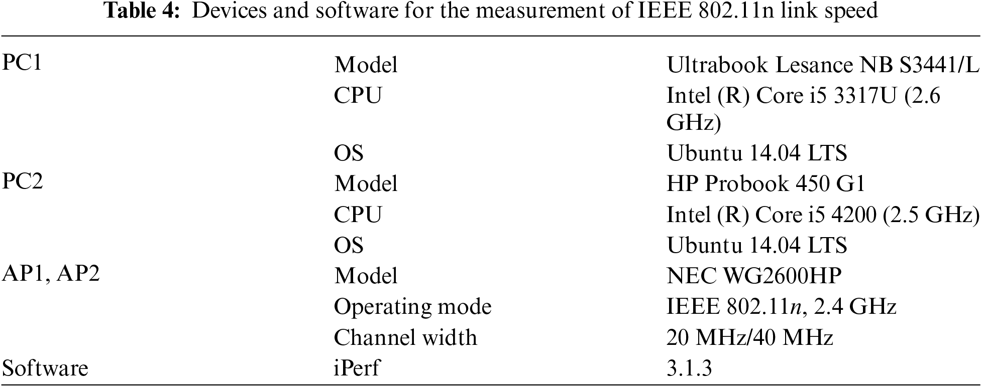

Figure 3: IEEE 802.11n link speed measurement results for 20 and 40 MHz channels
Both link speed and RSSI drastically drops sharply with the increase of transmission distance. Such stair-like changes in link speed and RSSI are caused by changes of MCS. The relationship between RSSI and link speed in measurement results is analyzed to yield estimated link speed,
where
where

Figure 4: IEEE 802.11n RSSI measurement results for 20 and 40 MHz channels

Figure 5: Link speed estimation from the measured RSSI for 20 MHz channel

Figure 6: Link speed estimation from the measured RSSI for 40 MHz channel
3 Proposed Channel Assignment Algorithm
In this section, we propose channel assignment algorithm to solve hierarchical optimization problem defined in Eq. (7) with an aim to minimize total interference in network. As depicted in Fig. 7, the proposed algorithm comprises four phases namely preprocessing, initial solution generation, iterative improvement and balancing load on channels. The preprocessing phase constructs an interference graph from the set of APs in network. Then, list of interfered APs for each AP is generated and an initial solution is developed using a greedy approach. The solution is iteratively improved using simulated annealing algorithm. Finally, load on each channel is averaged to improve network performance. In the following subsections, we respectively describe each phase of implementation.

Figure 7: Flow chart of proposed channel assignment algorithm
3.1 Channel Assignment Algorithm Step1: Preprocessing
In this section, we model an interference graph from set of APs and interference among them. Let,
Step 1: Preprocessing
① Calculate link speed of any pair AP and host in network. Link speed,
② Calculate communication time for every AP in network. The communication time
③ Generate list of interfered APs for each AP. The list of interfered APs,
a) Initialize
b) For each
3.2 Channel Assignment Algorithm Step 2: Initial Solution Generation
In the second step, an initial solution is generated. A straight forward method is to test all possibilities of channel assignment to every AP in the network. For m number of APs and k number of channels, there will be
Step 2: Initial Solution Generation
① Calculate interfered communication time
② Select a channel
③ Repeat this greedy selection for channel until each AP is allocated a channel that minimizes current interfered communication time.
④ Calculate total cost
3.3 Channel Assignment Algorithm Step 3: Iterative Improvement
In this step, initial solution generated in previous step is improved iteratively using simulated annealing (SA) algorithm. Greedy method for channel selection makes a locally optimal choice aiming to minimize overall interference. However, this does not yield an optimal solution. Therefore, herein, we utilize probabilistic technique of SA to approximate minimal interference. SA starts with the initial solution, selects an AP and a channel with random choice, and examines the changes in total interference. We keep the new selection if it reduces the total interference. Otherwise, we generate a random value between
Step 3: Iterative Improvement
① Select initial solution in the previous step as the current solution,
② Select one AP and one new channel as an alternative channel assignment. Calculate cost function with new channel,
③ Calculate
④ Otherwise, generate a pseudo-random value,
a) IF:
b) ELSE: keep previous channel assignment and
3.4 Channel Assignment Step 4: Balancing Load on Channels
In this step, we aim to balance load on operating channels. After allocation of channels to APs, some APs may become congested and some APs may not. Therefore, balancing of loads on channels is necessary to decrease network traffic and utilize channel capacity more efficiently. For this purpose, it is required to compute network load based on channels. Then, the load of channels can be balanced by changing associations of hosts in intersection of APs to low crowded AP. Thus, network performance achieved in previous step is further improved by applying procedure of averaging load on channels. The detail of the procedure is given below:
Step 4: Balancing Load on Channels
① Select an AP say
② Select a host say
The host is under coverage of another AP operating on a different channel other than
Link speed,
③ Select an AP say
④ Calculate cost function in Eq. (7) considering
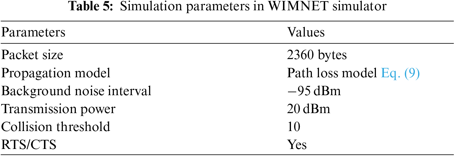
In this section, the efficiency of the proposal is verified using WIMNET simulator [30]. First, the accuracy of the throughput estimation is evaluated using proposed interference model. Then, the proposed channel assignment algorithm is evaluated under different network environments by using WIMNET simulator. The simulation is conducted on a platform of Intel (R) Core (TM) i5-4200 CPU
4.1 Evaluation of Proposed Interference Model
The proposed interference model is utilized in channel assignment algorithm where link speed is estimated considering interference of neighbor APs using the proposed interference. Therefore, the accuracy of the interference model is needed to verify before using in channel assignment algorithm. To verify the efficiency, we conduct a measurement campaign to collect actual link speed for different channel differences of an AP and its interfered APs at different physical distances. We considered 1 and 50 m physical distances for this work. Then, we compare the estimated link speed using proposed interference model with the actual link speed. The comparison results are shown in Figs. 8 and 9 non-bonded and bonded channels respectively. The estimated link speed using proposed interference model and measured link speed of the same link are shown in
4.2 Evaluation of Proposed Interference Model
First, we consider a random topology as depicted in Fig. 10 where 12 APs and 60 hosts are distributed in a 250 m
Next, we consider a regular network topology, as depicted in Fig. 11. The regular topology models 3rd floor of engineering building-3 in Okayama University, Japan. There are 6 rooms with 2 different room sizes: 7 m
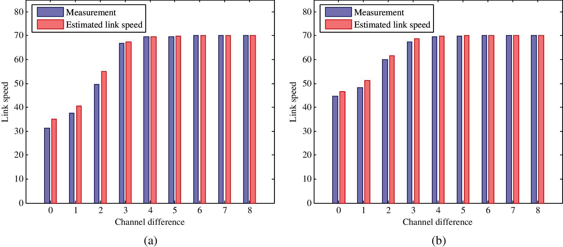
Figure 8: Measurement and estimated link speed of 20 MHz channel for different channel difference. (a) AP-AP distance is 1 m (b) AP-AP distance is 50 m

Figure 9: Measurement and estimated link speed of 40 MHz channel for different channel difference. (a) AP-AP distance is 1 m (b) AP-AP distance is 50 m
Now, to evaluate proposed channel assignment algorithm, we compare network throughputs obtained by random assignment of channels, greedy channel assignment and proposed algorithm assignment. Here, the random channel assignment experiment is repeated

Figure 10: Random topology with 12 APs and 60 hosts

Figure 11: Regular topology with 9 APs and 60 hosts
The throughput for combination of bonded and non-bonded channels is expected to be better for flexibility of selection of partial overlapping channels. The numerical results in Fig. 12 demonstrate that the proposed algorithm can successfully assign channels in both topologies to reduce interference compared to random and greedy assignment. The network throughput is comparatively higher in random topology than that of regular topology. This is because, the regular topology is denser than random topology and all the APs are within the coverage of each other. Nonetheless, even in such extreme dense network environment, proposed algorithm works well in assigning channels to improve network performance by reducing overall network interference.

Figure 12: Comparison results of random and regular topologies among random, greedy and proposed channel assignment algorithms
In this work, we study interference of channels to improve network performance by reducing interference. We propose an interference model for IEEE 802.11n protocol under partially overlapping channels. The proposed model addresses interference of both non-bonded channel and bonded channel. We formulate a hierarchical optimization problem of channel assignment for minimization of total interference in the network. It has been found that reducing the network interference is almost proportional to increasing overall performance of the network. Then, a channel assignment algorithm of partially overlapping channels is introduced using proposed channel interference model in WLAN system. The experimental results showed that the proposed channel assignment algorithm successfully selects the best channel combination and optimizes the network performance. We believe that proposed interference model and algorithm open a new door for installation of WLAN system that specially benefits large-scale network where numerous APs are deployed. The proposal is verified by numerical experiments using WIMNET simulator under several network topologies. In future, we will consider other performance metrics e.g., transmission power, jitter for further improvement of proposed algorithm and dynamic channel width selection in order to improve network performance.
Acknowledgement: Authors would like to thank those who contributed to accomplish this work and provide us with valuable comments.
Funding Statement: The authors received no specific funding for this study.
Conflicts of Interest: The authors declare that they have no conflict of interest to report regarding the present study.
1. S. Manzoor, Z. Chen, Y. Gao, X. Hei and W. Cheng, “Towards QoSaware load balancing for high density software defined Wi-Fi networks,” IEEE Access, vol. 8, pp. 117623–117638, 2020. [Google Scholar]
2. H. S. Oh, D. G. Jeong and W. S. Jeon, “Joint radio resource management of channel-assignment and user-association for load balancing in dense WLAN environment,” IEEE Access, vol. 8, pp. 69615–69628, 2020. [Google Scholar]
3. S. Kim, K. Lee, Y. Kim, J. Shin, S. Shin et al., “Dynamic control for on-demand interference-managed WLAN infrastructures,” IEEE/ACM Transactions on Networking, vol. 28, no. 1, pp. 84–97, 2019. [Google Scholar]
4. R. Karmakar, S. Chattopadhyay and S. Chakraborty, “Novel AP association and fair channel access in high throughput WLAN for energy efficiency,” Ad Hoc Networks, vol. 103, pp. 1–18, 2020. [Google Scholar]
5. M. S. A. Mamun, N. Funabiki, K. S. Lwin, M. E. Islam and W. C. Kao, “A channel assignment extension of active access-point configuration algorithm for elastic WLAN system and its implementation using raspberry Pi,” International Journal of Networking and Computing, vol. 7, no. 2, pp. 248–270, 2017. [Google Scholar]
6. C. C. Gómez, I. M. Maestre, J. M. G. Guzman and S. S. Sanz, “A coral reefs optimization algorithm with substrate layer for robust Wi-Fi channel assignment,” Soft Computing, vol. 23, pp. 12621–12640, 2019. [Google Scholar]
7. A. Ali and F. A. Khan, “Condition and location-aware channel switching scheme for multi-hop multi-band WLANs,” Computer Networks, vol. 168, pp. 1–12, 2020. [Google Scholar]
8. L. Deek, E. G. Villegas, E. Belding, S. Lee and K. Almeroth, “Intelligent channel bonding in 802.11n WLANs,” IEEE Transactions on Mobile Computing, vol. 13, no. 6, pp. 1242–1255, 2013. [Google Scholar]
9. A. Faridi, B. Bellalta and A. Checco, “Analysis of dynamic channel bonding in dense networks of WLANs,” IEEE Transactions on Mobile Computing, vol. 16, no. 8, pp. 2118–2131, 2016. [Google Scholar]
10. K. Zhou, X. Jia, Y. Chang and X. Tang, “Partially overlapping channel assignment for WLANs using SINR interference model,” International Journal of Communication Systems, vol. 27, no. 11, pp. 3082–3095, 2014. [Google Scholar]
11. J. Lei, J. Jiang and F. Shang, “Channel assignment mechanism for multiple APs cochannel deployment in high density WLANs,” Wireless Communications and Mobile Computing, vol. 2018, pp. 1–11, 2018. [Google Scholar]
12. D. Gong, M. Zhao and Y. Yang, “Channel assignment in multi-rate 802.11n WLANs,” in Wireless Communications and Networking Conference, Shanghai, China, pp. 392–397, 2013. [Google Scholar]
13. B. Kaufmann, F. Baccelli, A. Chaintreau, V. Mhatre, K. Papagiannaki et al., “Measurement-based self organization of interfering 802.11 wireless access networks,” in Int. Conf. on Computer Communications, Anchorage, AK, USA, pp. 1451–1459, 2007. [Google Scholar]
14. C. C. Hsu, Y. A. Liang, J. L. G. Gomez, C. F. Chou and C. J. Lin, “Distributed flexible channel assignment in WLANs,” in Wireless Communications and Networking Conference, Shanghai, China, pp. 493–498, 2013. [Google Scholar]
15. H. Zhang, H. Ji and W. Ge, “Channel assignment with fairness for multi-AP WLAN based on distributed coordination,” in Wireless Communications and Networking Conference, Cancun, Mexico, pp. 392–397, 2011. [Google Scholar]
16. D. Xu, Z. Feng, Y. Li and P. Zhang, “Fair channel allocation and power control for uplink and downlink cognitive radio networks,” in IEEE GLOBECOM Workshops, Houston, TX, USA, pp. 591–596, 2011. [Google Scholar]
17. Y. Wu, Y. Sun, Y. Ji, J. Mao and Y. Liu, “A joint channel allocation and power control scheme for interference mitigation in high density WLANs,” in Int. Conf. on Communication Technology, Guilin, China, pp. 98–103, 2013. [Google Scholar]
18. I. Dolinska, M. Jakubowski, A. Masiukiewicz, G. Rzkadkowski and K. Piórczynski, “A minimum-spanning-tree-inspired algorithm for channel assignment in 802.11 networks,” International Journal of Electronics and Telecommunications, vol. 62, no. 4, pp. 379–388, 2016. [Google Scholar]
19. A. Farsi, N. Achir and K. Boussetta, “WLAN planning: Separate and joint optimization of both access point placement and channel assignment,” Annals of Telecommunications, vol. 70, pp. 263–274, 2015. [Google Scholar]
20. M. Burton, Channel Overlap Calculations for 80211b Networks. White Paper, London, UK: Cirond Networks Inc., 2002. [Google Scholar]
21. A. Aditya, J. Glenn, S. Srinivasan and S. Peter, “Self-management in chaotic wireless deployments,” in Int. Conf. on Mobile Computing and Networking, New York, USA, pp. 185–199, 2005. [Google Scholar]
22. T. D. Chiueh, P. Y. Tsai and I. W. Lai, “Baseband Receiver Design for Wireless MIMO-OFDM Communications,” 2nd ed., Singapore: Wiley-IEEE Press, 2012. [Google Scholar]
23. M. S. A. Mamun, M. E. Islam and N. Funabiki, “An active access-point configuration algorithm for elastic wireless local-area network system using heterogeneous devices,” International Journal of Networking and Computing, vol. 6, no. 2, pp. 395–419, 2016. [Google Scholar]
24. K. S. Lwin, N. Funabiki, C. Taniguchi, K. K. Zaw, M. S. A. Mamun et al., “A minimax approach for access point setup optimization in IEEE 802.11n wireless networks,” International Journal of Networking and Computing, vol. 7, no. 2, pp. 187–207, 2017. [Google Scholar]
25. M. Humphrys, “Continuous output-the sigmoid function,” Accessed: Jul. 20, 2021. [Online]. Available: https://www.computing.dcu.ie,/~humphrys/Notes/Neural/sigmoid.html. [Google Scholar]
26. T. S. Rappaport, Wireless Communications: Principles and Practice. vol. 2, New Jersey: Prentice hall PTR, 1996. [Google Scholar]
27. D. B. Faria, “Modeling Signal Attenuation in IEEE 802.11 Wireless LANs,” Technical Report, TR-KP06-0118, California, USA: Stanford University, 2005. [Google Scholar]
28. WiFi Channel Scanner, Accessed: Jul. 20, 2021. [Online]. Available: http://www.wifichannelscanner.com/. [Google Scholar]
29. “iPerf-the ultimate speed test tool for TCP, UDP and SCTP,” Accessed: Jul. 20, 2021. [Online]. Available: https://iperf.fr/. [Google Scholar]
30. N. Funabiki, “Wireless mesh networks,” London, UK: InTechOpen Publisher, 2011. Accessed: Jul. 20, 2021. [Online]. Available: https://www.intechopen.com/books/wireless-mesh-networks. [Google Scholar]
 | This work is licensed under a Creative Commons Attribution 4.0 International License, which permits unrestricted use, distribution, and reproduction in any medium, provided the original work is properly cited. |