DOI:10.32604/cmc.2022.023033
| Computers, Materials & Continua DOI:10.32604/cmc.2022.023033 | |
| Article |
The Roll Stability Analysis of Semi-Trailer Based on the Wheel Force
1Collage of Instrumental Science and Engineering, Southeast University, Nanjing, 210096, China
2North Carolina State University, Raleigh, 27695, USA
*Corresponding Author: Dong Wang. Email: kingeast16@seu.edu.cn
Received: 26 August 2021; Accepted: 27 September 2021
Abstract: It is different for the liquid tank semi-trailer to keep roll stability during turning or emergency voidance, and that may cause serious accidents. Although the scholars did lots of research about the roll stability of liquid tank semi-trailer in theory by calculating and simulation, how to make an effective early warning of rollover is still unsolved in practice. The reasons include the complex driving condition and the difficulty of the vehicle parameter obtaining. The feasible method used currently is evaluating the roll stability of a liquid tank semi-trailer by the lateral acceleration or the attitude of the vehicle. Unfortunately, the lateral acceleration is more useful for sideslip rather than rollover, and the attitude is a kind of posterior way, which means it is hard to take measures to cope with the rollover accident when the attitude exceeds the safety threshold. Considering the movement of the vehicle is totally caused by the wheel force, the rollover could also be predicted by the changing of the wheel force. Therefore, in this paper, we developed a method to analyze the roll stability by the vertical wheel force. A thorough experiment environment is established, and the effectiveness of the proposed method is verified in real driving conditions.
Keywords: Roll stability; wheel force; liquid tank semi-trailer; real driving conditions
The liquid tank semi-trailer has become the main carrier for liquid chemical products transportation, because of the large transportation capacity and low transportation costs [1,2]. And it also brings serious safety risks for the road traffic. The report shows that the accident probability caused by the liquid tank semi-trailer accounts for about 80% of all dangerous goods transportation.
Like the ordinary heavy-duty semi-trailers, the liquid tank semi-trailer has a high center of gravity, a large load, a narrower track relative to the height of the vehicle, and a coupling effect between the tractor and the trailer [3]. All these factors lead to a quite low roll stability limit for the liquid tank semi-trailer. The literature shows nearly one-third accidents of heavy semi-trailers are rollover [4–6].
What’s worse is that the liquid in the tank has no definite shape and is fluid during driving [7,8]. That makes the trailer system is always in an unstable state and has the characteristics of low rollover threshold. In the actual transportation process, due to the limitation of vehicle axle load on the road transportation, the different density of liquid cargo, the restriction of thermal expansion, and contraction cause the liquid to not fill the entire tank, which means the trailer is essentially in partially filled condition [9,10]. In this situation, the liquid sloshing in the tank of the trailer has an obvious coupling effect with the dynamics of the whole vehicle [11]. Therefore, compared with ordinary heavy-duty semi-trailers, the roll stability of liquid tank semi-trailer is more difficult to be guaranteed, especially under driving conditions such as emergency braking, high-speed lane change or obstacle avoidance [12].
Therefore, to intervene the vehicle effectively before a rollover accident occurs, it is necessary to evaluate the roll stability of the liquid tank semi-trailer during driving by the vehicle dynamic parameters sensing. The rest of this study is organized as follows. Section 2 analyzes the dynamic model in the rollover processing and the proposed evaluation standard. Section 3 describes the design details of the vertical wheel force acquisition equipment, which is indeed a specially manufactured wheel force sensor. Section 4 introduces the test equipment for the actual vehicle experiment, including the distribution of the sensors and the protective equipment, and the experiment results of the real liquid tank semi-trailer are also shown in this section. At last, Section 5 concludes the paper.
2 Roll Dynamics Model and the Evaluation Standard of Roll Stability
The roll dynamics model is essential to study the vehicle roll phenomenon. Considering that the roll of the trailer part is the main form of the vehicle roll, and the rear axle of the trailer is the dangerous point of the vehicle roll instability, the rear axle of the trailer is selected to establish the roll dynamics model in this paper, as shown in Fig. 1 [13], and the model could be also described by (1).
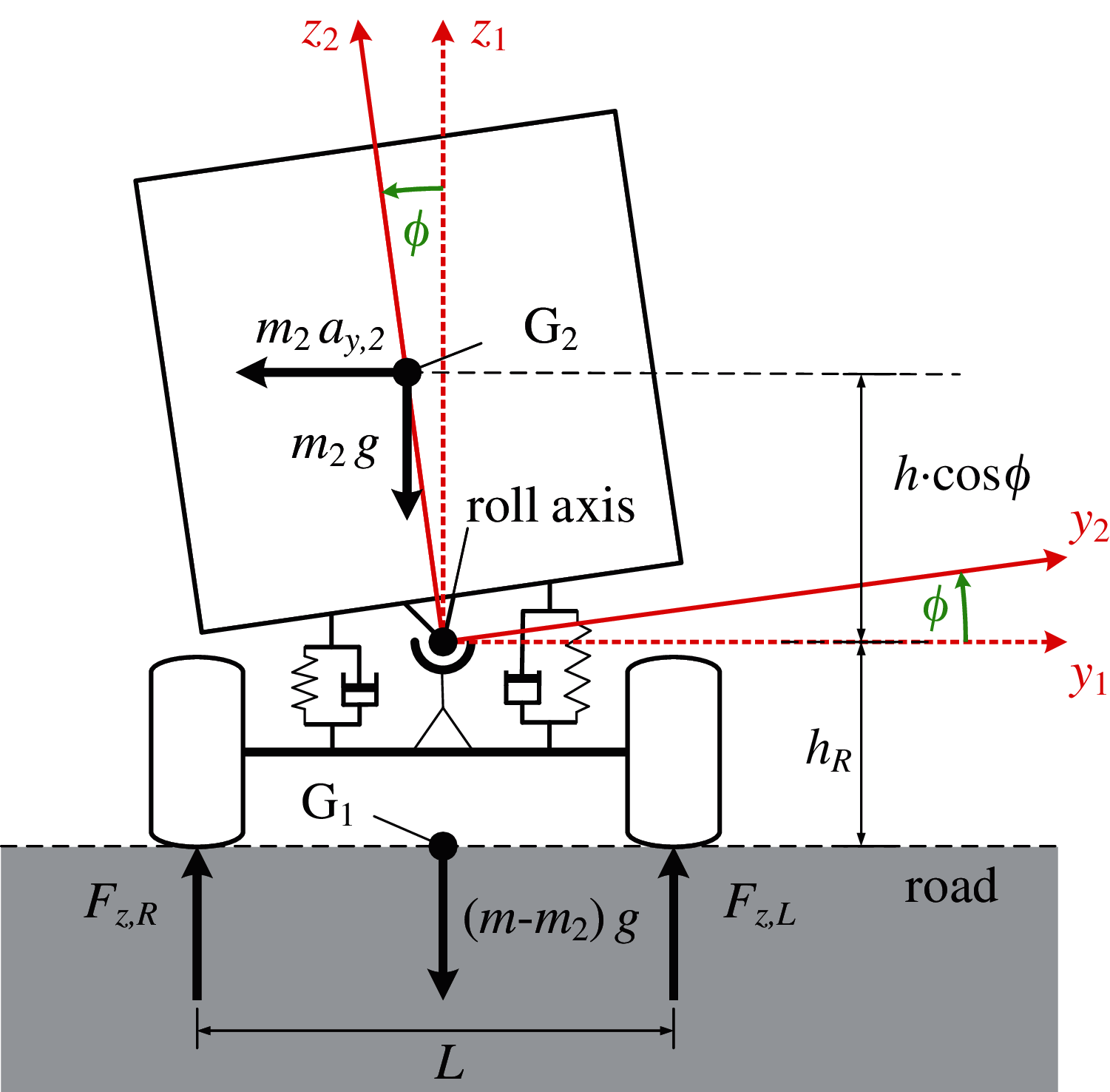
Figure 1: Roll dynamics model
The states in (1) are the roll angle
2.2 Criterion of Roll Stability
During the driving of the vehicle, even if there is a center of gravity deviation or lateral acceleration, as long as the road surface can provide sufficient support to balance the roll torque generated by the above situation, the vehicle will not roll over. A large number of simulations and experiments show that rollover accidents usually occur when the balance torque provided by the road surface is insufficient. Therefore, the rollover coefficient
Where
Because the vertical wheel forces are hard to be obtained in real time, they are often estimated by using the roll dynamics model shown in Fig. 1. And at this time, Eq. (2) could be written in the form of (2). Where
Furthermore, Assuming
Unfortunately, for the liquid tank semi-trailer, the liquid in the tank might shake during the driving condition, which causes the position of the center of gravity of the tank to change. That means the parameter
3 Design of the Wheel Force Sensor
The wheel force sensor could measure various forces between the wheel and the road and of course, it has to be installed on the wheel itself. Since the wheel is rotating during driving, there is a difference between the sensing coordinate and the calculating coordinate of the wheel force. To deal with this problem, two coordinates are defined, respectively in Fig. 2.
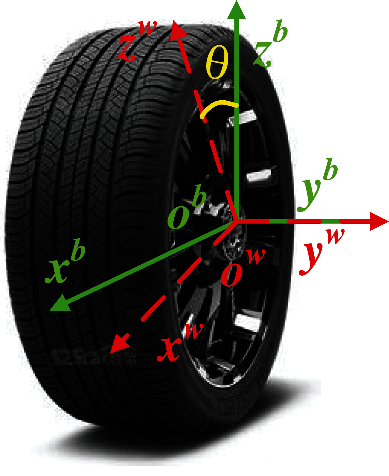
Figure 2: Definition of the coordinates
In Fig. 2, the vehicle body coordinate {obxbybzb} (wheel force calculating coordinate) is relatively stationary with the body of the trailer with ob on the centre of the wheel, obzb perpendicular to the ground, obxb to the front of the trailer body, and obyb to the side. In addition, the origin of the wheel coordinate {owxwywzw} (wheel force sensing coordinate) coincides with that of {obxbybzb}, and is fixed on the wheel.
It is worth to note that these two coordinates completely coincide at the beginning, then as the wheel rotates, the coordinate {owxwywzw} rotates around the obxb axis relative to {obxbybzb}. At this time, the conversion relationship between two coordinates could be described in (5).
In the scene that this paper is concerned about, the measurement of vertical force is essential [16]. However, due to the rotation of the wheel, the vertical and longitudinal forces are coupled with each other in the sensing process, and it can be seen from (5) that the relationship between the measured wheel forces in the wheel coordinate {owxwywzw} and the actual wheel forces in the wheel coordinate {obxbybzb} obeys (6). Where
In order to sense both vertical and longitudinal wheel forces, a spoke elastic body is designed as in Fig. 3 [17]. The inner ring of the elastic body is connected to the axle of the trailer, and the outer ring is connected to the wheel. When the wheel is under force, the eight strain beams located between the inner and the outer ring will be slightly deformed, and these deformations can be converted into electrical signals by the bridge composed of resistance strain gauges [18].
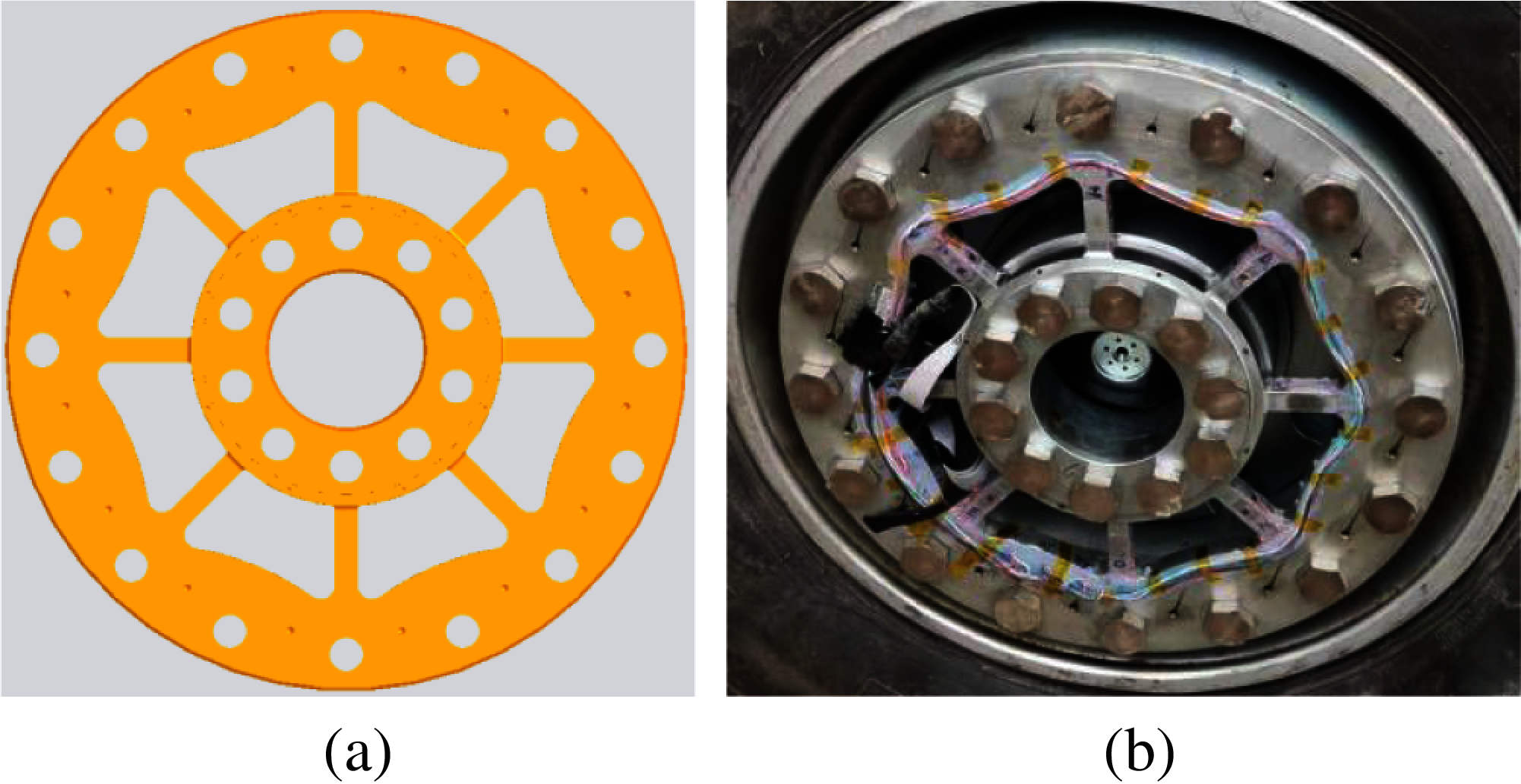
Figure 3: Elastic body: (a) Design diagram; (b) Physical photo
The division of strain gauges on the strain beams is shown in Fig. 4 [19]. Specifically, the strain gauges, which are used to sense
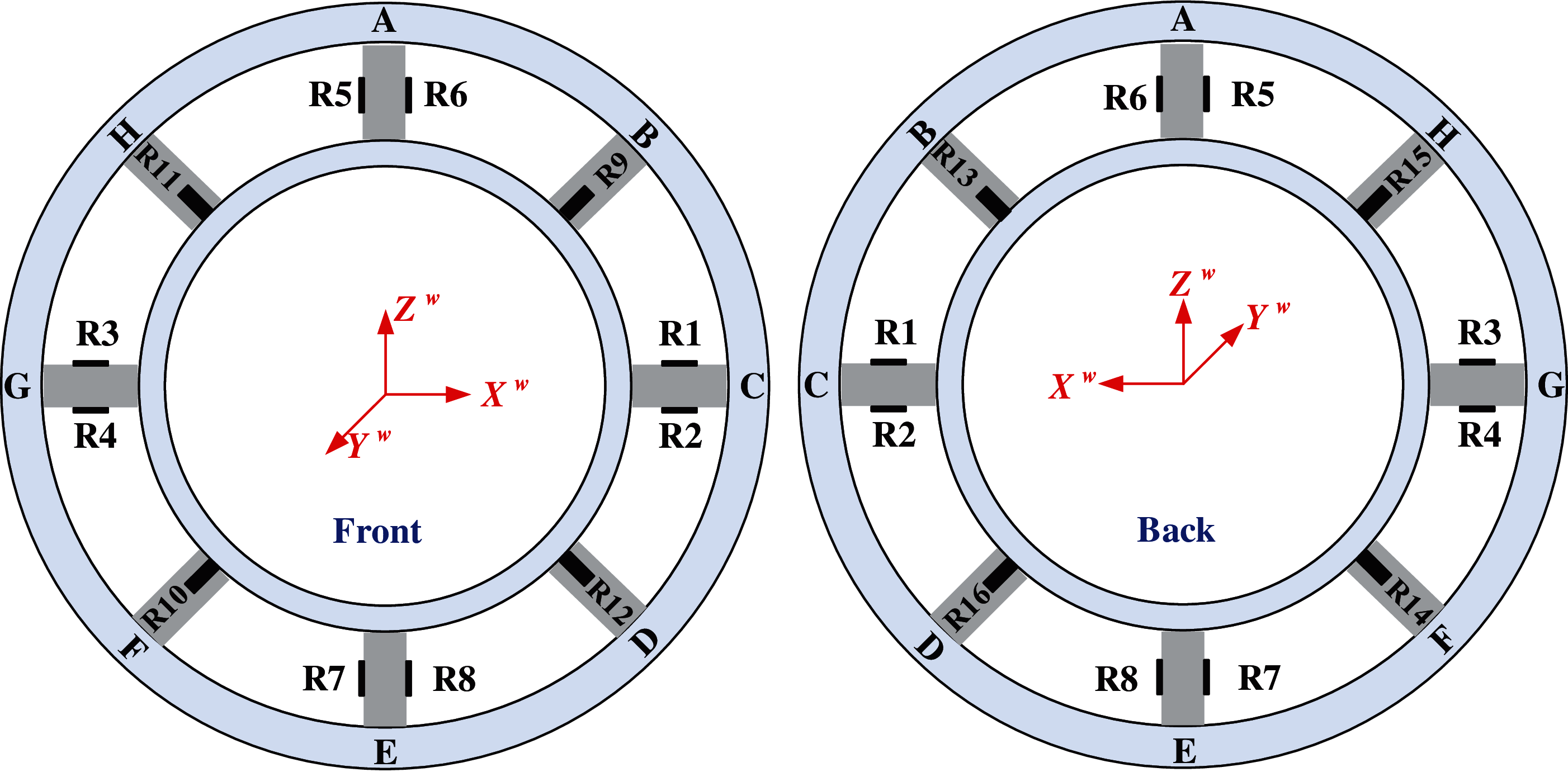
Figure 4: Division of strain gauges
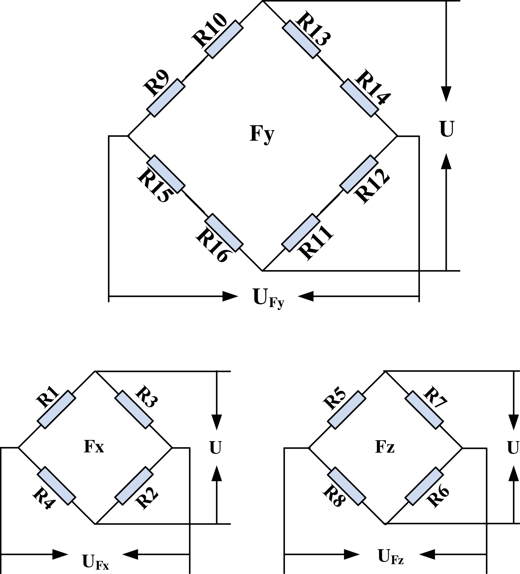
Figure 5: Differential bridge
Fig. 6 shows the complete wheel force sensor assembly [22]. The elastic body (④) connects the axle and the rim (②) by the inner and outer ring flanges (① and ③), and in order not to interfere with the axle head, the special flanges are relatively long. The elastic body and the strain gauges on it are protected by the metal cover (⑤) to keep the water and dust away. The encoder and the signal acquisition circuit are located in the circuit box (⑥). The fastener (⑦) is used to fix one end of the encoder to the trailer body, so that the output of the encoder could directly reflect the rotation angle of the wheel.
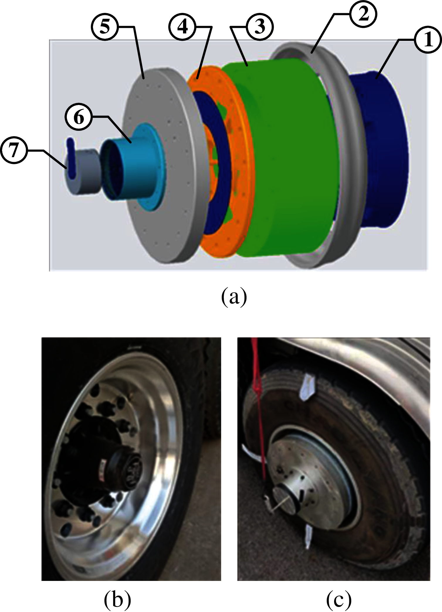
Figure 6: Wheel force sensor assembly: (a) Exploded view of the wheel force sensor assembly; (b) Axle head; (c) Physical photo
The wheel force information collected by the wheel force sensor will be wirelessly transmitted to the processing terminal on the trailer via Bluetooth, and decoupling calculations will be performed to obtain the actual wheel force. As in Figs. 7 and 8, the raw data obtained directly by the wheel force sensor shows an oscillating waveform due to the rotation of the wheel, and the oscillation amplitudes of
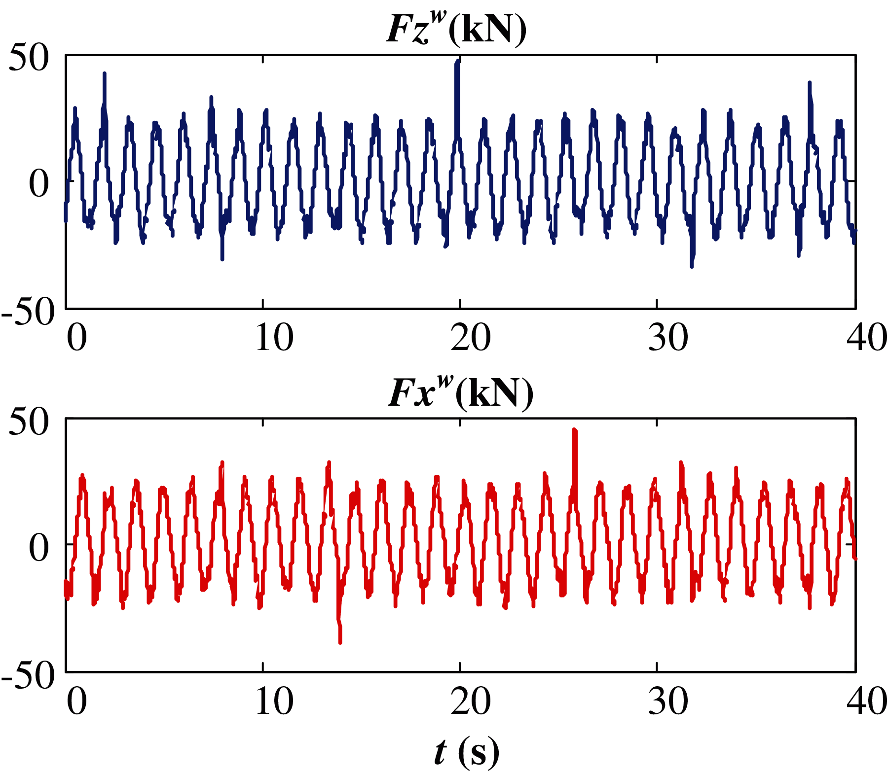
Figure 7: Raw wheel forces in the wheel coordinate
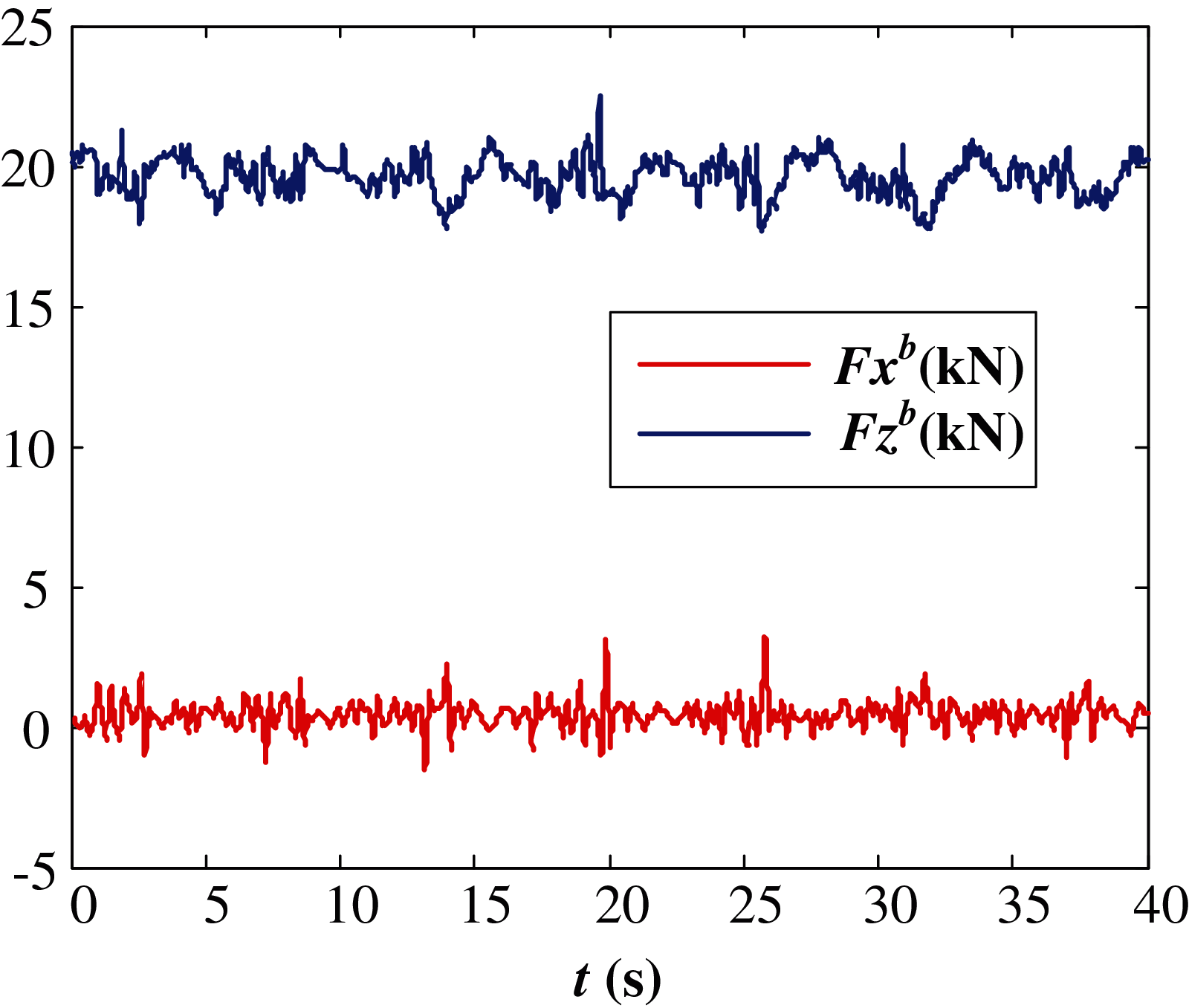
Figure 8: Decoupling wheel forces in the trailer body coordinate
In order to test the actual effect of the trailer rollover stability analysis method used in this paper, on the premise of ensuring the safety of personnel, a liquid tank semi-trailer is modified according to the method shown in Fig. 9.
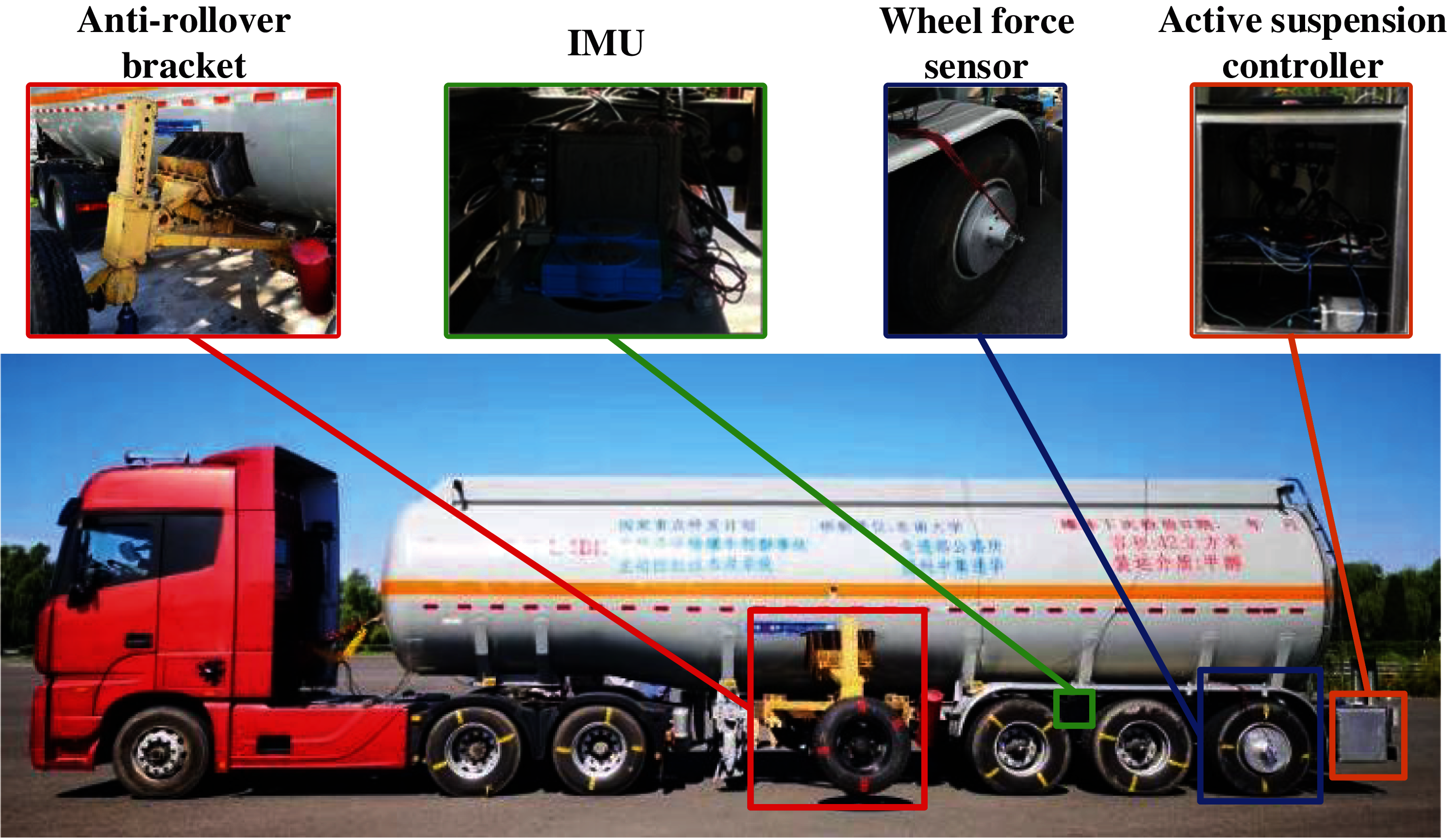
Figure 9: Liquid tank semi-trailer for experiment
First of all, an anti-rollover bracket is fixed on both sides of the tank. This bracket could provide effective support when the trailer is about to roll over, thereby avoiding accidents and ensuring the safety of the driver. Then the active suspension is equipped to adjust the pressure of the hydraulic lever, so that the trailer can regain its balance when a roll is about to occur. This active suspension can reduce the risk of rolling effectively, and its control signal could also be used to verify the analysis results of rollover stability based on wheel force. At last, two sets of sensors are installed to obtain the driving information of the semi-trailer. One is the high-precision inertial measurement unit (IMU), and the other is the wheel force sensor. The IMU is put on the middle of the trailer and is used to sense the three-axis acceleration and angular velocity. The Wheel force sensors are installed on the last axle of the trailer to measure the longitudinal and vertical wheel forces on the left and right sides, since the research shows that the last axle is where the rollover often occurs.
4.2.1 Half-Load Steady State Rotation Test
The half-load steady state rotation test, which is widely used in the roll stability analysis, is carried out to compare the three stability criteria of wheel force, lateral acceleration, and roll angle. To ensure safety, the professional vehicle test site and experienced drivers are selected to carry out the dangerous test. The trailer trajectory of the test which consists of three intact left and right turns, is shown in the Fig. 10.
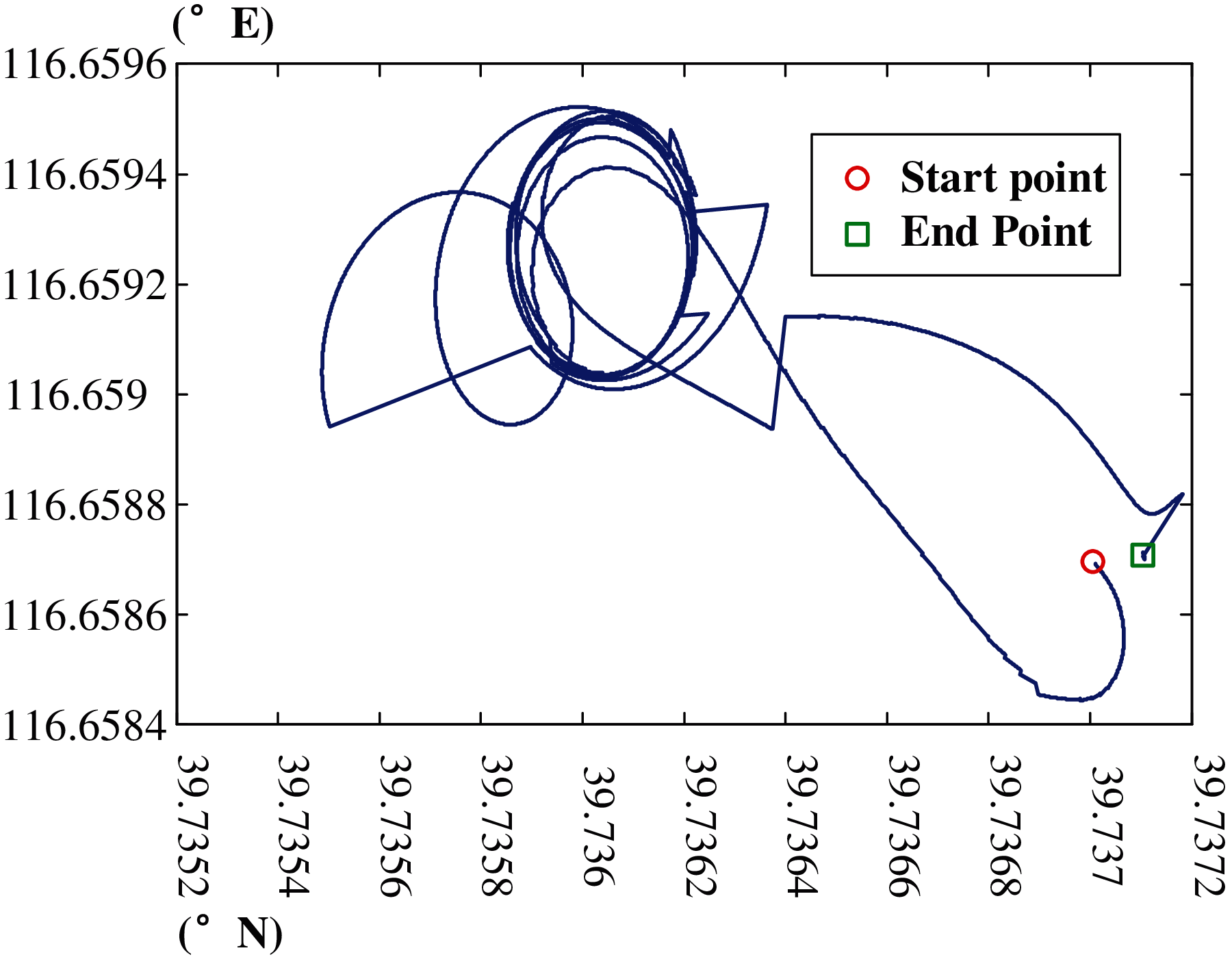
Figure 10: Trajectory of the half-load steady state rotation test
The wheel forces and vehicle speed in the half-load steady state rotation test are shown in Fig. 11. It can be clearly seen from the figure that the trend of wheel force is basically the same as the trailer speed. When the trailer is driving in a straight line, the vertical forces on the left and right wheel are almost the same, since the trailer is in balance. However, when the trailer begins to turn, the pressure increases in the turning direction and decreases in the opposite. Thus, the vertical forces on both sides change reversely.
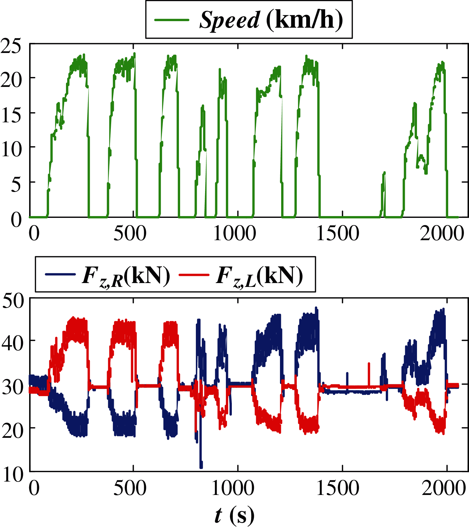
Figure 11: Data of the half-load steady state rotation test
The comparison of the three roll stability criteria including wheel force, lateral acceleration, and roll angle are in Fig. 12. What can be noticed is that the three criteria have the same general trends but different details. In the zoomed-in figure, it could be found that when the trailer has a rollover risk, the first thing that is sensitive to this change is
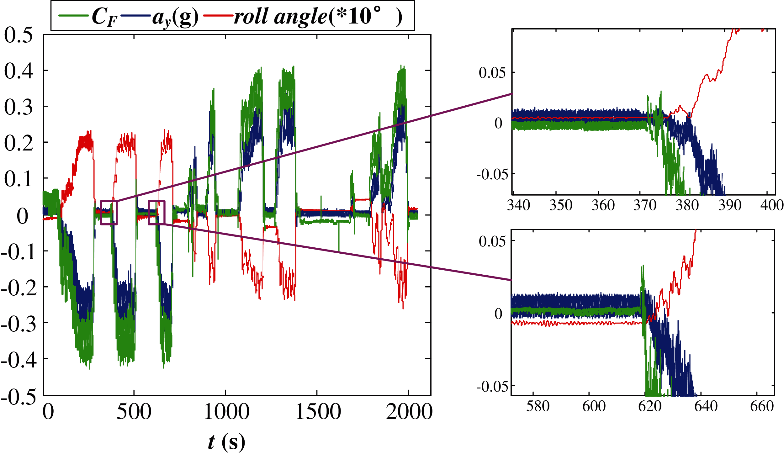
Figure 12: Comparison of the three roll stability criteria in half-load steady state rotation test
The steering brake test is highly dangerous since the speed of the trailer is higher, and the brake pedal needs to be depressed while turning [23]. The changing of the speed and the situation of the EBS signal of the active suspension (20 means on and 0 means off) in the steering brake test is shown in Fig. 13. It is obviously that there are three severe decelerations in this test, and the decrease speed are 1.32 m/s2 (around the 50th second, decreased by 11.4 km/h in 2.4 s), 1.50 m/s2 (around the 150th second, decreased by 11.9 km/h in 2.2 s) and 1.49 m/s2 (around the 275th second, decreased by 12.9 km/h in 2.4 s) respectively. These three decelerations have all triggered the active suspension controller. Furthermore, Fig.14 shows that the response sensitivity of the
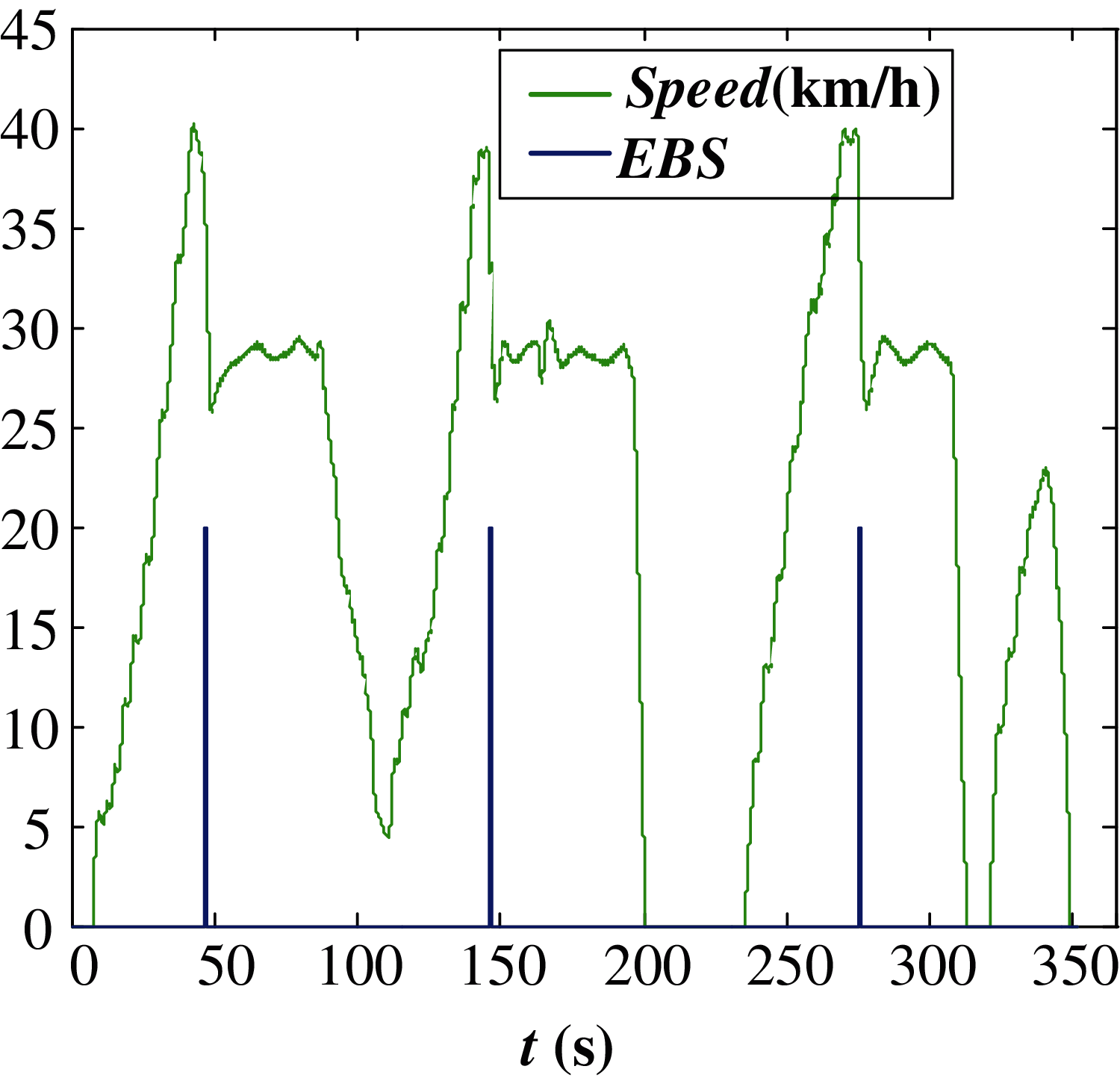
Figure 13: Data of the steering brake test
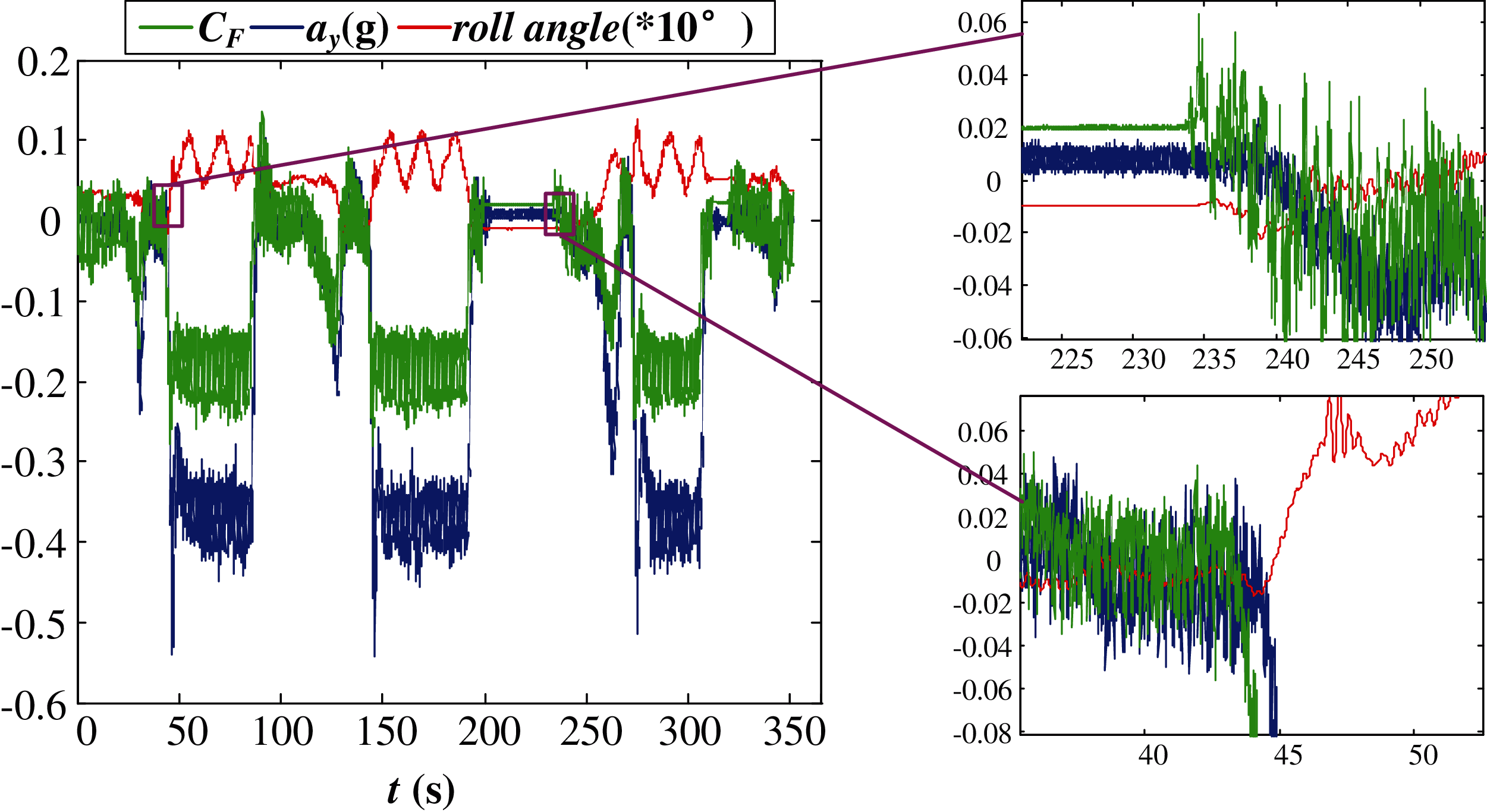
Figure 14: Comparison of the three roll stability criteria in steering brake test
The rollover stability analysis is crucial for the liquid tank semi-trailer to guarantee the safety of the driver and the equipment. Compare with the lateral acceleration and roll angle, the rollover coefficient
Acknowledgement: This work was supported by the Suzhou Key industrial technology innovation project SYG202031.
Funding Statement: This work was supported by the Suzhou Key industrial technology innovation project SYG202031.
Conflicts of Interest: The authors declare that they have no conflicts of interest to report regarding the present study.
1. Y. Q. Sun, C. Cole and M. Spiryagin, “Monitoring vertical wheel-rail contact forces based on freight wagon inverse modelling,” Advances in Mechanical Engineering, vol. 7, no. 5, pp. 1–11, 2015. [Google Scholar]
2. G. Xia, M. Zhao, X. Tang, S. Wang and L. Zhao, “Linear reversing control of semi-trailer trains based on hitch angle stable and feasible domain,” Control Engineering Practice, vol. 104, no. 1, pp. 104625, 2020. [Google Scholar]
3. S. Q. Zhang, H. Sun, Y. F. Zhang and Y. Liu, “Analyze and control on the flexible body of tractor semi-trailer rollover,” in Int.Conf. on Mechanics Design, Manufacturing and Automation (MDMSuzhou, ChinaHINA, pp. 607–611, 2017. [Google Scholar]
4. C. Cheng and D. Cebon, “Improving roll stability of articulated heavy vehicles using active semi-trailer steering,” Vehicle System Dynamics, vol. 46, no. sup1, pp. 373–388, 2008. [Google Scholar]
5. D. Han, B. Shen, W. Zhou, X. Zhang and Q. Li, “The study of tanker semi-trailer’s steering stability on the fluid-structure interaction,” Procedia Environmental Sciences, vol. 12, no. 2, pp. 1082–1088, 2009. [Google Scholar]
6. Z. Zhao, M. Feng, G. Peng, J. Liu and Y. Tao, “Simulation and analysis on rollover stability of heavy semi-trailer train based on Trucksim,” in 3rd Int. Conf. on Intelligent Green Building and Smart Grid, Yilan, Taiwan, China, Natl Ilan Univ, pp. 1–4, 2018. [Google Scholar]
7. J. Semetko, I. Janosko and P. Pernis, “Increase of driving pulls of the tractor by trailer,” in 31st Int. Symp. on Agricultural Engineering, Opatija, Croatia, pp. 59–64, 2003. [Google Scholar]
8. S. Zhou, S. Zhang, G. Zhao and C. Tang, “Lateral stability control of car-trailer combination based on 4WS,” in 2010 Int. Conf. on Measuring Technology and Mechatronics Automation, Changsha, China, vol. 2, pp. 576–579, 2010. [Google Scholar]
9. W. Sun, X. Zhang, S. Shi and X. He, “Vehicle classification approach based on the combined texture and shape features with a compressive DL,” IET Intelligent Transport Systems, vol. 13, no. 7, pp. 1069–1077, 2019. [Google Scholar]
10. X. Wang and Q. Wang, “Application of dynamic programming algorithm based on model predictive control in hybrid electric vehicle control strategy,” Journal of Internet of Things, vol. 2, no. 2, pp. 81–87, 2020. [Google Scholar]
11. D. Wu, Y. Liu, Z. Xu and W. Shang, “Design and development of unmanned surface vehicle for meteorological monitoring,” Intelligent Automation & Soft Computing, vol. 26, no. 5, pp. 1123–1138, 2020. [Google Scholar]
12. H. Wang, Q. Xue, T. Cui, Y. Li and H. Zeng, “Cold start problem of vehicle model recognition under cross-scenario based on transfer learning,” Computers Materials & Continua, vol. 63, no. 1, pp. 337–351, 2020. [Google Scholar]
13. D. Odenthal, T. Bünte and J. Ackermann, “Nonlinear steering and braking control for vehicle rollover avoidance,” in 1999 European Control Conf., Karlsruhe, Germany, pp. 598–603, 1999. [Google Scholar]
14. J. Wang, T. Zhang, B. Jin and S. Wu, “A novel sins/iusbl integration navigation strategy for underwater vehicles,” Journal of Cyber Security, vol. 1, no. 1, pp. 1–10, 2019. [Google Scholar]
15. L. Zhu, Y. Wang, L. Wang and Z. Wu, “Stability analysis of transfer alignment filter based on the m theory,” Computers Materials & Continua, vol. 59, no. 3, pp. 1015–1026, 2019. [Google Scholar]
16. X. Zhang, X. Yu, W. Sun and A. Song, “An optimized model for the local compression deformation of soft tissue,” KSII Transactions on Internet and Information Systems, vol. 14, no. 2, pp. 671–686, 2020. [Google Scholar]
17. M. Kieninger, A. Rupp and K. Rueffer, “A new wheel force transducer for the investigation of loads on rail bound vehicles in the urban traffic,” Materialprufung, vol. 50, no. 1–2, pp. 42–50, 2008. [Google Scholar]
18. X. Zhang, H. Wu, W. Sun, A. Song and S. K. Jha, “A fast and accurate vascular tissue simulation model based on point primitive method,” Intelligent Automation and Soft Computing, vol. 27, no. 3, pp. 873–889, 2021. [Google Scholar]
19. D. Wang, S. Chen, X. Li, W. Zhang and H. Jin, “Research on rotational angle measurement for the smart wheel force sensor,” Sensors, vol. 20, no. 4, pp. 1037, 2020. [Google Scholar]
20. D. Fujiwara, T. Oshima and K. Iizuka, “Measuring the normal stress distribution acting on a locked-wheel of push-pull locomotion rovers via a wheel sensor system,” Sensors (Switzerland), vol. 20, no. 16, pp. 1–22, 2020. [Google Scholar]
21. D. D. Falco, G. D. Massa, S. Pagano and S. Strano, “Wheel force transducer for shimmy investigation,” Lateral, vol. 2218, pp. 1207–1212, 2015. [Google Scholar]
22. D. Wang, G. Lin, W. Zhang and T. Jiang, “Angle error compensation in wheel force transducer,” Measurement, vol. 77, no. 2, pp. 203–212, 2016. [Google Scholar]
23. A. M. C. Odhams, R. L. Roebuck, B. A. Jujnovich and D. Cebon, “Active steering of a tractor-semi-trailer,” Proceedings of the Institution of Mechanical Engineers, Part D: Journal of Automobile Engineering, vol. 225, no. 7, pp. 847–869, 2011. [Google Scholar]
 | This work is licensed under a Creative Commons Attribution 4.0 International License, which permits unrestricted use, distribution, and reproduction in any medium, provided the original work is properly cited. |