DOI:10.32604/cmc.2022.022289
| Computers, Materials & Continua DOI:10.32604/cmc.2022.022289 | |
| Article |
Gain Enhancement of Dielectric Resonator Antenna Using Electromagnetic Bandgap Structure
1Department of Medical Equipment Technology, College of Applied Medical Sciences, Majmaah University, 11952, Almajmaah, Saudi Arabia
2Microwave Electronics Research Laboratory, Department of Physics, Faculty of Mathematical, Physical and Natural Sciences of Tunis, Tunis El Manar University, Tunis, 2092, Tunisia
*Corresponding Author: Amor Smida. Email: a.smida@mu.edu.sa
Received: 03 August 2021; Accepted: 04 September 2021
Abstract: High gain antennas are highly desirable for long-range wireless communication systems. In this paper, a compact, low profile, and high gain dielectric resonator antenna is proposed, fabricated, experimentally tested, and verified. The proposed antenna system has a cylindrical dielectric resonator antenna with a height of 9 mm and a radius of 6.35 mm as a radiating element. The proposed dielectric resonator antenna is sourced with a slot while the slot is excited with a rectangular microstrip transmission line. The microstrip transmission line is designed for a 50 Ω impedance to provide maximum power to the slot. As a result, the proposed antenna operates at 5.15 GHz with a 10-dB absolute bandwidth of 430 MHz (4.98 – 5.41 GHz). It is important to mention that the gain of the dielectric resonator antenna is enhanced by the introduction of an electromagnetic bandgap (EBG) structure. In fact, EBG units are placed below the antenna, which enhances the realized peak gain from 5.32 dBi to 8.36 dBi at 5.15 GHz. More specifically, a gain enhancement of 3.04 dB is observed with the introduction of the EBG array. This antenna has several good features such as high gain, compact size, large bandwidth, and lower losses which make it a suitable choice for long-range wireless communication systems.
Keywords: High gain antennas; dielectric resonator antenna; metamaterial; high gain; efficiency; bandwidth; resonant frequency
In the recent era, dielectric resonator antennas have gained much appreciation due to their promising characteristics such as lower losses, light-weight, high-quality factors, and effectiveness [1–3]. However, dielectric resonator antennas mostly have lower gains which cannot fulfill the modern wireless communication requirements. Therefore, it is always desirable to design a dielectric resonator antennas-based system with higher gain values over a large frequency band [4–6].
In addition, the 3D geometry of dielectric resonator antennas supports many choices for exciting them. More specifically, many modes inside the dielectric resonator antennas can be excited by choosing a proper excitation model and method. It supports many excitations methods such as slot feeding, microstrip feeding, parasitic element feeding, probe feeding, and many more. In contrast, the microstrip technology-based components, such as antennas, filters, diplexers and so many more suffer from higher losses, copper geometry and skin effect, narrow bandwidth, lower quality factor, and lower efficiencies [7,8]. In literature, many high-performance dielectric resonator antennas have been designed, fabricated, and experimentally tested. In [9], a cylindrical dielectric resonator is reported. The reported antenna has cylindrical geometry and operates at 5.25 GHz with a bandwidth of 340 MHz. This antenna is excited through a rectangular slot to excite the HEM11 mode inside it. Then, the initially constructed dielectric resonator antenna is modified to convert it into two different types of chemical sensors. In fact, cylindrical microwells are incorporated in the DRA to check different types of chemicals. The chemical detection is based on resonant frequencies. More specifically, each chemical has a different resonant frequency based on its permittivity and loss tangent value. The authors of [10] reported an integrated filter-antenna subsystem for modern radio-frequency (RF) front-ends. In fact, a single resonator-based microstrip filter is designed on an FR-4 substrate and then integrated with a cylindrical dielectric resonator antenna to construct an integrated filter-antenna subsystem. The reported subsystem has a realized peak gain of 1.52 dBi and radiation efficiency of 93% at the resonant frequency. In [11], a circular dielectric resonator antenna is designed for fifth-generation (5G) applications where the dielectric resonator is excited with a square slot and parasitic patches. The parasitic patches are excited in such a manner that they enable circular and linear polarization in the antenna. In fact, the reported antenna operates at three different states (1) mode 1: when all parasitic patches are deactivated the antenna operates at linear polarization, (2) mode 2: when two diagonal parasitic patches are activated, the antenna operates at left-handed circular polarization, and (3) mode 3: when rest of the diagonal parasitic patches are activated, the antenna operates at right-handed circular polarization. In all three cases, the impedance bandwidth is larger than 750 MHz, 3-dB axial ratio bandwidth is larger than 21.4%, gains are higher than 5.25 dBi, and radiation efficiencies are higher than 79.8%. The authors of [12] reported a dual-band antenna for wearable biomedical applications. The reported antenna operates at 2.45 GHz and 5.8 GHz where the resonance at 2.4 GHz is generated by an L-shaped slot and resonance at 5.8 GHz is generated by a cylindrical dielectric resonator antenna. In fact, the reported antenna is excited with a microstrip transmission line; it excites the fundamental TM10 mode in the L-shaped slot and HEM11 mode in the cylindrical dielectric resonator antenna. Finally, the antenna is embedded inside a rectangular biomedical device for testing purposes. Moreover, both bands of the reported antenna are independently controllable with acceptable gains of 2.01 dBi and 5.84 dBi, respectively. In [13], a dual-band cylindrical dielectric resonator antenna is reported at 4.4 GHz and 6.1 GHz with a 10-dB impedance bandwidth of 600 MHz and 500 MHz, respectively. In both bands, the dielectric resonator antenna resonates using HEM11 mode with peak realized gains of 4.9 dBi and 5.6 dBi. Initially, a conventional dielectric resonator antenna is reported and then adding circular copper strips on its top to operate at dual bands. As a result, the radiation efficiency of higher than 88% is obtained in both bands. Moreover, the radiation patterns in both bands are unidirectional with a front-to-back ratio (FTBR) of more than 10.08 dB. It is worth mentioning that the in-band performance of the above antennas is good; however, all of them suffer from lower gains, which make their applications difficult in modern wireless communication where larger coverage and high data rates are required.
As mentioned earlier that dielectric resonator antennas have good properties as compared to their counterpart microstrip technology. But dielectric resonator antenna suffers from lower gains values. Therefore, many approaches have been opted to tackle this problem of lower gains and to improve the gain of the antenna system. In fact, antenna gain is an important factor in considering antenna performance. It has a direct relationship with the channel capacity of the antenna which is very vital in long-range wireless communications. So far, several approaches have been applied to dielectric resonator antennas to enhance their performance in terms of realized peak gains. In [14], different layers of dielectric materials of unique and high permittivity are placed above one another and sourced with a common input. As a result of this configuration, the authors enabled 1.2 dB gain enhancement. In [15], two circular disk dielectric resonator antennas are used with some offset to achieve higher gain at the band of interest. The authors of [16] used stacked dielectric resonator antennas configuration to maximize the realized peak gain of the antenna. Moreover, an air gap between the patch and dielectric resonator antenna is maintained to further boost the realized peak gains at the resonant band. Similarly, the authors of [17,18] used short horns for gain enhancements, where short horns are surface-mounted. It is worth mentioning that these approaches achieve higher gains but also increases the size and cost of the wireless communication device. In addition, electromagnetic bandgap (EBG) structures are used to enhance antennas characteristics [19–22].
In this paper, the limitations of the aforementioned techniques are solved and a novel technique for gain improvement is proposed. In this paper, series of EBG structures are added below the dielectric resonator antenna to enhance gain and other radiation characteristics of the antenna. The major contributions of the proposed work are summarized as follows:
• To the best of the author's knowledge, this is the most compact dielectric resonator antenna, with improved peak realized gain, is proposed so far.
• Gain improvement of more than 3.04 dB is achieved using series of EBG below the dielectric resonator antenna.
This paper covers the initial description of the dielectric resonator antenna, theoretical analysis of the antenna, operational principles of the dielectric resonator antenna. In addition, simulated and measured results of the dielectric resonator with and without backing by EBG array structures are presented and discussed.
Fig. 1 illustrates the 3D view, top view, bottom view, and side view of the proposed dielectric resonator antenna. The dielectric resonator has cylindrical dimensions and is made of alumina material (dielectric constant = 9.8 and loss tangent = 0.0009). The cylindrical dielectric resonator has a radius of 6.35 mm and a height of 9 mm. This specific height and radius of the cylindrical dielectric resonator antenna are selected due to its commercial availability and cost-effectiveness. This dielectric resonator antenna block is placed on the FR-4 substrate. The FR-4 substrate has a thickness of 1.6 mm, a dielectric constant of 4.4, and a loss tangent of 0.019. The FR-4 substrate has a length of 40 mm, width of 40 mm, and height of 1.6 mm.
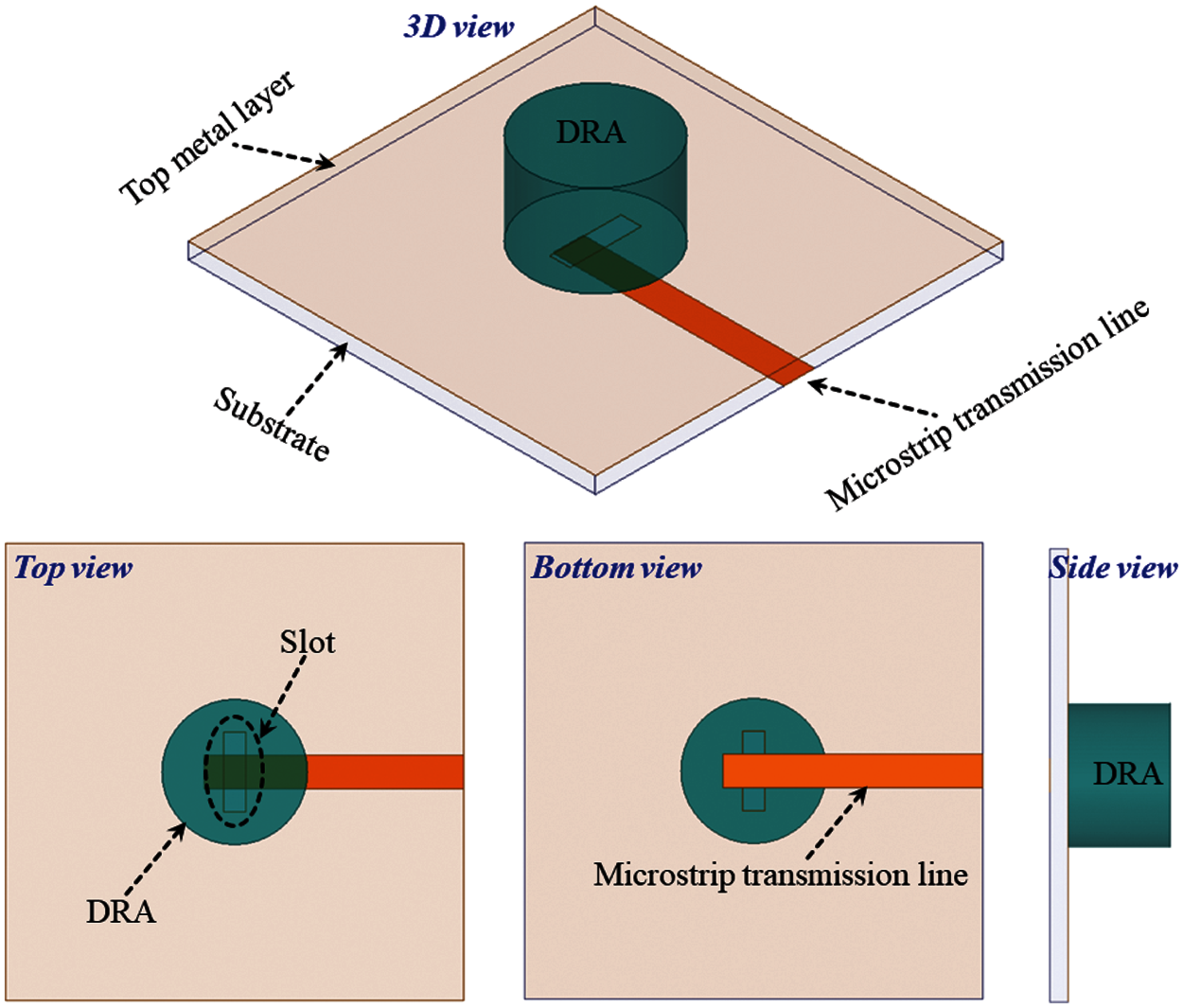
Figure 1: 3D view, top view, bottom view, and side view of the proposed dielectric resonator antenna (DRA: dielectric resonator antenna)
A full ground plane is designed on the top side of the FR-4 substrate and a microstrip transmission line is made on the bottom side of the substrate. Once the rectangular slot is etched on copper of the top side of the FR-4 substrate. The slot is located at the center of the FR-4 substrate with a length of 8 mm and a width of 1.8 mm. On the bottom side of the substrate, a rectangular microstrip transmission line is located which is 22 mm long and 3 mm wide. The length and width of the rectangular microstrip transmission line are selected to perfectly match the source for maximum power transfer. In fact, the source has an input impedance of 50Ω [23–25]. Therefore, the microstrip transmission line is also calculated for a 50Ω impedance to transfer maximum power. The following equations are used to determine the input impedance and width of the transmission line.
where W is the width of the transmission line, h is the thickness of the transmission line, and Z is the input impedance of the transmission line.
The design process of the proposed dielectric resonator antenna is started with performing eigenmode analysis. In fact, eigenmode analysis of the dielectric resonator antenna cylinder is performed in the absence of a source. This analysis is important in order to understand the location (frequencies) of different modes inside the cylindrical dielectric resonator antenna. While doing the analysis, for this specific dielectric resonator antenna, the first mode is found as HEM11 mode. As mentioned earlier that many excitation methods are applicable for exciting different modes in the dielectric resonator antennas. Out of all other methods, slot excitation is very easy to implement. In fact, slot excitation effectively excites the fundamental HEM11 mode inside the dielectric resonator antenna. In reality, a rectangular slot below the dielectric resonator antenna acts as a magnetic dipole. As a result, magnetic fields reside along the length of the slot. Therefore, the magnetic fields of the dielectric resonator also follow the same patterns. Fig. 2 shows the electric field and magnetic field distribution of the HEM11 mode of the dielectric resonator antenna at the resonant frequency of the antenna. It can be clearly seen that the magnetic fields are oriented in the direction of the length of the slot. This is because the magnetic dipole of the slot is tending them to orient in the same direction. It is well-known that electric fields are always perpendicular to the magnetic fields [26–28]. The same phenomenon is also found in this design.
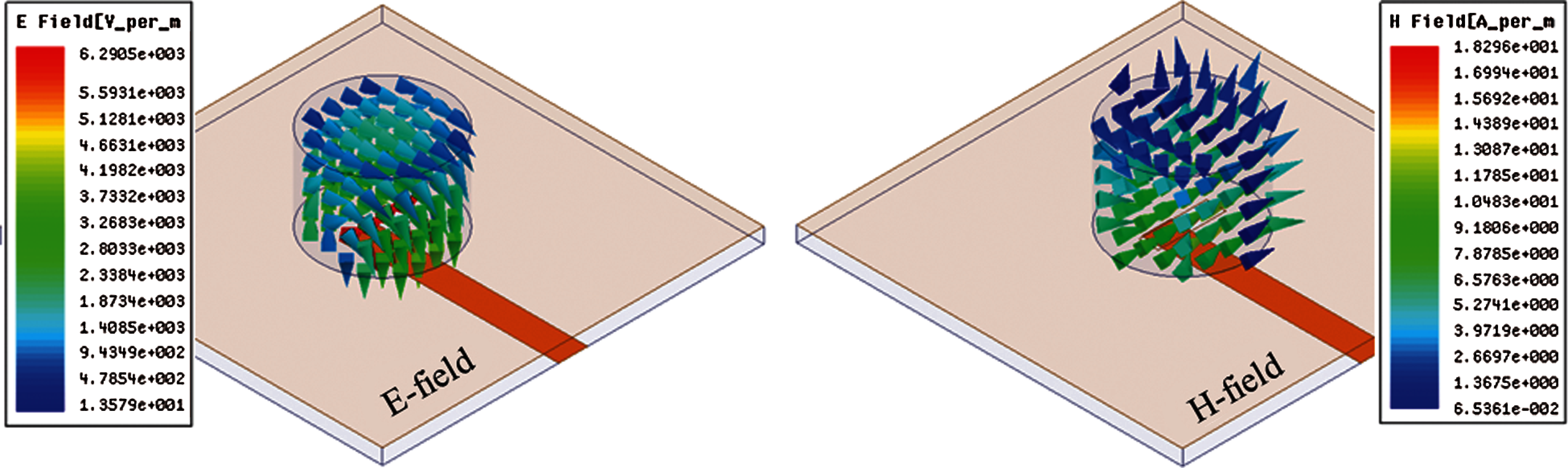
Figure 2: Electric and magnetic field distribution of the HEM11 mode of the dielectric resonator antenna at the resonant frequency
After calculating the microstrip transmission line's length and width, slot's length and width, the dimensions (radius and height) of the dielectric resonator antenna are calculated. In fact, the dimensions of the dielectric resonator antenna specify the operating frequency of the antenna. More specifically, by changing the diameter or height of the dielectric resonator disc, the resonant frequency of the system can be changed. The following equations are used to calculate the radius and height of the dielectric resonator antenna. It is worth mentioning that initially, the dimensions are calculated using the following equations but later on optimize for better impedance matching and impedance bandwidth.
and
where a wavenumber is identified with Ko, the radius of the cylindrical dielectric resonator antenna is expressed as R which is 6.35 mm in this scenario, speed of the light in a vacuum is denoted as c, the height of the cylindrical dielectric resonator antenna is denoted with H which is 9 mm in this case,
Once the resonant frequency is determined using (1) and (2). Then these relations are further expanded to get the height of the dielectric resonator antenna. After determining the radius, height, and resonant frequency of the cylindrical dielectric resonator antenna, further analysis is performed using High-Frequency Structure Simulator (HFSS) tool. Using HFSS, series of simulations are performed to enhance impedance matching, impedance bandwidth, and radiation properties. In fact, rectangular slot's length, rectangular slot's width, rectangular slot's position, microstrip transmission line width, and microstrip transmission line length are varied to achieve the expected results.
After achieving the desired results using HFSS, an equivalent lumped element circuit model is developed for the proposed antenna, as shown in Fig. 3. It can be observed that coupling between the source and slot is designed as an impedance transformer with an X1 ratio. Moreover, the rectangular slot is modeled as an RLC circuit. It is important to mention that slot does not radiate in this case but still is considered as a radiating element. Therefore, a slot is designed as an RLC circuit. Similarly, the cylindrical dielectric resonator antenna is a radiating element and thereby expressed as an RLC circuit. Furthermore, the coupling between the slot and dielectric resonator antenna is expressed as an impedance transformer with an impedance ratio of X2.
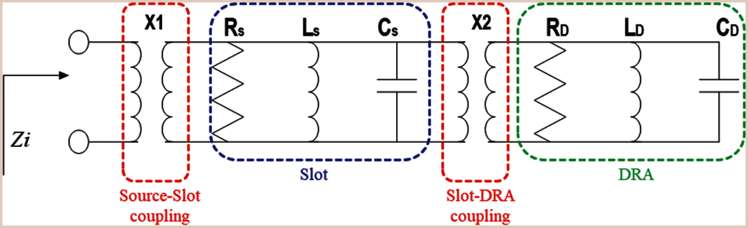
Figure 3: Lumped element equivalent circuit model of the proposed slot-excited cylindrical dielectric resonator antenna (DRA: dielectric resonator antenna)
In the equivalent circuit model, Zi is the input impedance from the source which is 50Ω in this case, X1 impedance transformer ratio which determines matching between the transmission line and rectangular slot, Rs is the resistance of the rectangular slot, Ls is the inductance of the rectangular slot, Cs is the capacitance of the rectangular slot, X2 is the impedance transformer ratio which expresses the slot and dielectric resonator coupling, RD is the resistance of the dielectric resonator antenna, LD is the inductance of the dielectric resonator antenna and CD is the capacitance of the dielectric resonator antenna.
The simulated and measured results of the antenna are discussed in this section. Fig. 4 illustrates the reflection coefficient of the dielectric resonator antenna when the antenna is sourced with 1 W of input power. The results of the reflection coefficient are important because several antenna parameters can be extracted from it such as (1) Resonant frequency of the antenna, which shows that at which frequency the antenna is more matched, (2) impedance matching which shows that how much power from source is transferred to load (the dielectric resonator antenna), (3) impedance bandwidth of the antenna which identifies the operational bandwidth of the antenna, and (4) lower and upper-frequency limits of the operational frequency. Based on Fig. 4, the following results are concluded:
• This antenna has a resonant frequency of 5.15 GHz.
• This antenna has a 10-dB operational bandwidth of 430 MHz.
• The lower operational frequency limit is 4.98 GHz and the higher operating frequency limit is 5.41 GHz.
• The impedance matching of the antenna is good between 4.98 GHz and 5.41 GHz.
• More than 90% of the available power is delivered to the load (antenna) from 4.98 GHz to 5.41 GHz.
• At 5.15 GHz, the reflection coefficient value is equal to −30 dB. At this frequency, almost 99% of the total power is delivered to the load.
• It can also be observed that the reflection coefficient curve has no dips (impedance matching) in the lower and higher frequency region which makes it resistant to any interferences.
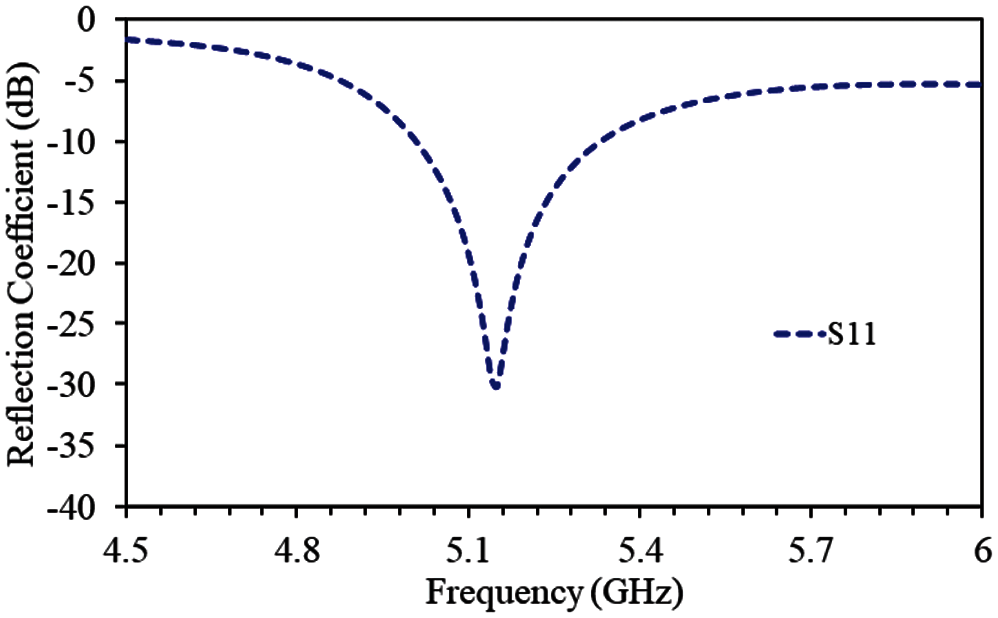
Figure 4: Reflection coefficient of the cylindrical dielectric resonator antenna without the introduction of EBG structure arrays
Gain is one of the important parameters to be considered in analyzing any system. In fact, the gain has a direct relationship with the antenna coverage and data rates. More specifically, the antenna coverage is higher for higher gains. Similarly, the antenna supports high data rates when its gain is higher. For the proposed antenna, the peak realized gain is 5.32 dBi at 5.15 GHz, as shown in Fig. 5.
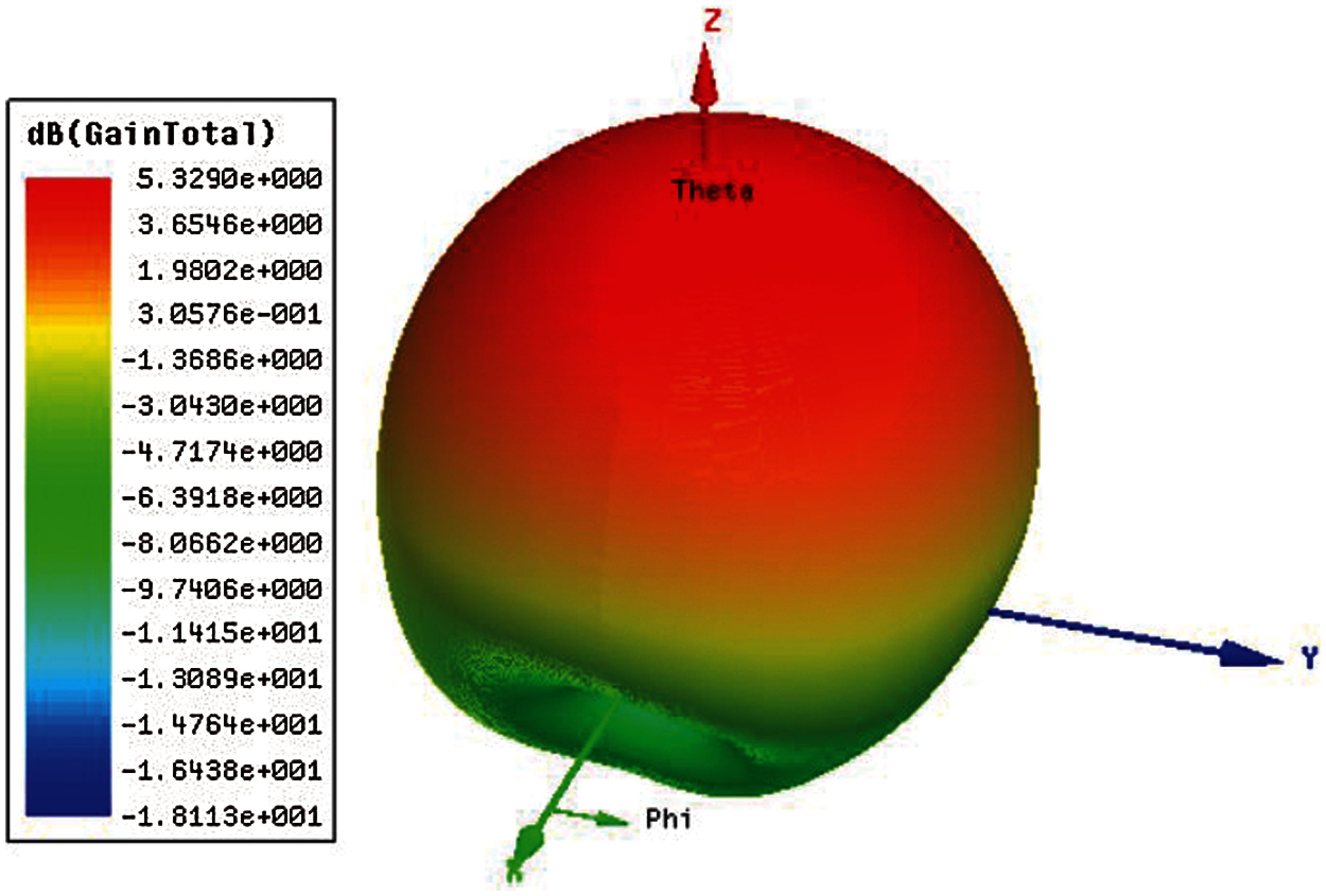
Figure 5: Peak realized gain of the antenna at 5.15 GHz
As mentioned earlier that dielectric resonator antennas have good properties as compared to their counter-part microstrip technology. But dielectric resonator antenna suffers from lower gains values. Gain has a direct relationship with the channel capacity of the antenna which is very vital in long-range wireless communications. So far, several approaches have been applied to dielectric resonator antennas to enhance their performance in terms of realized peak gains. In this design, the EBG structure array is used to enhance the gain of the antenna, as shown in Fig. 6.
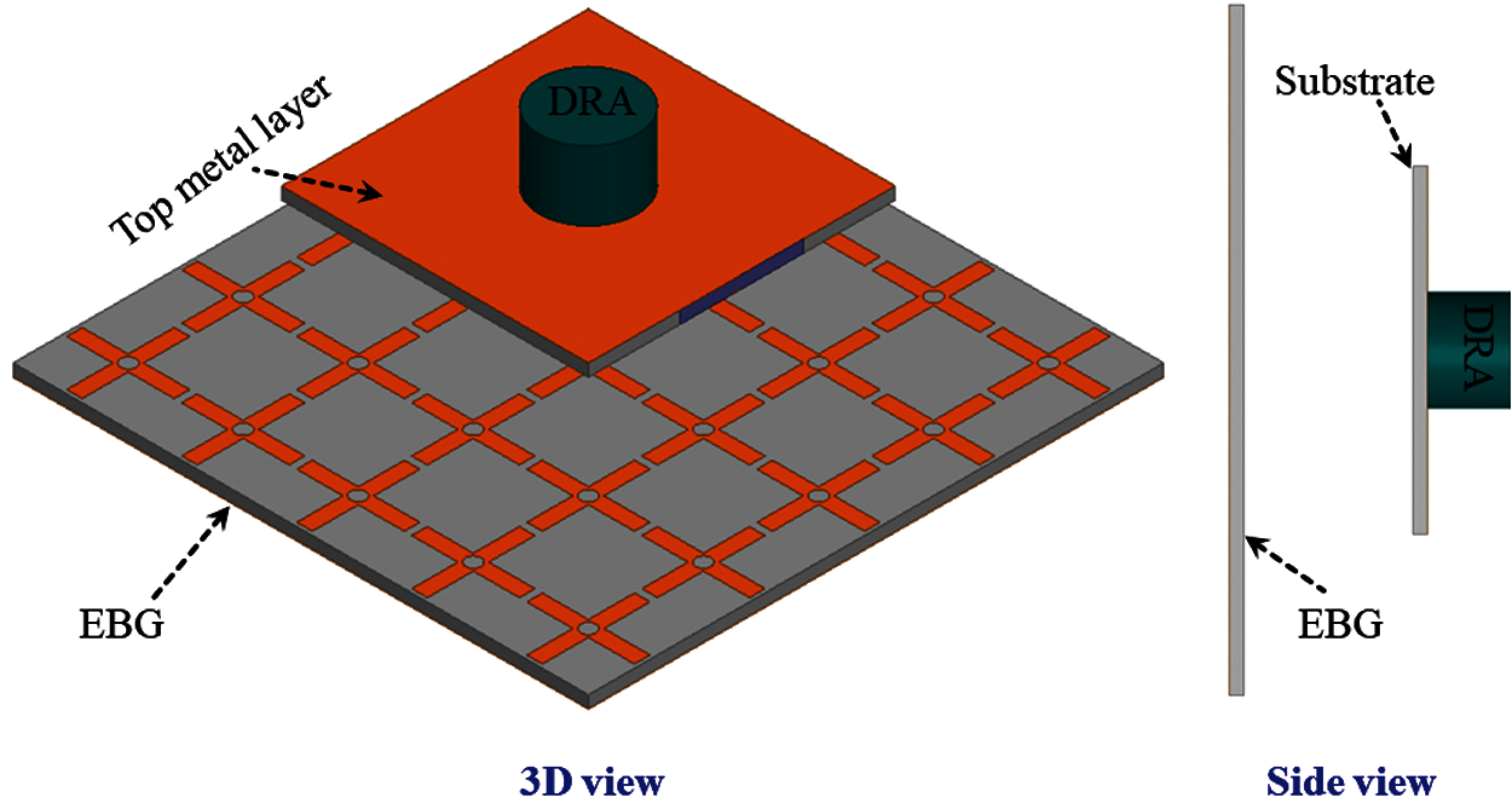
Figure 6: Geometry (3D view and side view) of the antenna in the presence of the EBG (75 × 75 × 1 mm3)
After analyzing the proposed dielectric resonator antenna without using an EBG structure array, it is optimized by placing the EBG array below the antenna. A gap of 10 mm is realized between the antenna and EBG array. The EBG array has full ground plane. It can be observed that the reflection coefficient of the antenna remains the same, as shown in Fig. 7. Same as the reference antenna, this antenna also resonates at 5.15 GHz. Once the antenna is optimized with EBG structure arrays, then it is fabricated. The EBG structure array is fabricated on a 1 mm thick FR-4 substrate. The cylindrical dielectric resonator is placed on a 1.6 mm thick FR-4 substrate material. The simulation of the antenna is performed using the HFSS tool. After the fabrication of this prototype, the reflection coefficient is measured by connecting the antenna with the vector network analyzer. Similarly, the radiation properties of this antenna are measured inside the anechoic chamber.
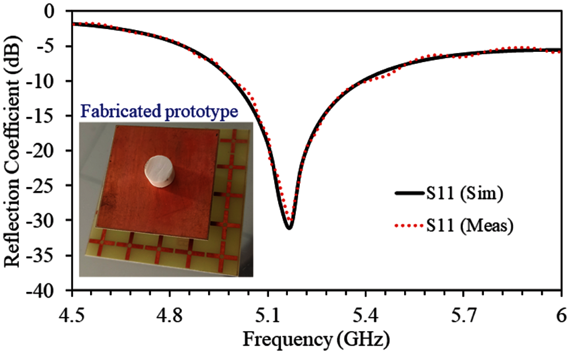
Figure 7: Fabricated prototype, simulated reflection coefficient, and measured reflection coefficient of the EBG array-backed dielectric resonator antenna
The simulated and measured peak gains of the antenna with and without EBG structure arrays are shown in Fig. 8. It can be observed that the realized peak gains are enhanced with the addition of EBG. More specifically, a gain enhancement of 3.04 dB is observed with the introduction of the EBG array. The realized peak of 5.32 dBi is found at 5.15 GHz in the absence of EBG and the peak realized gain of 8.36 dBi is found in the presence of EBG structure arrays.
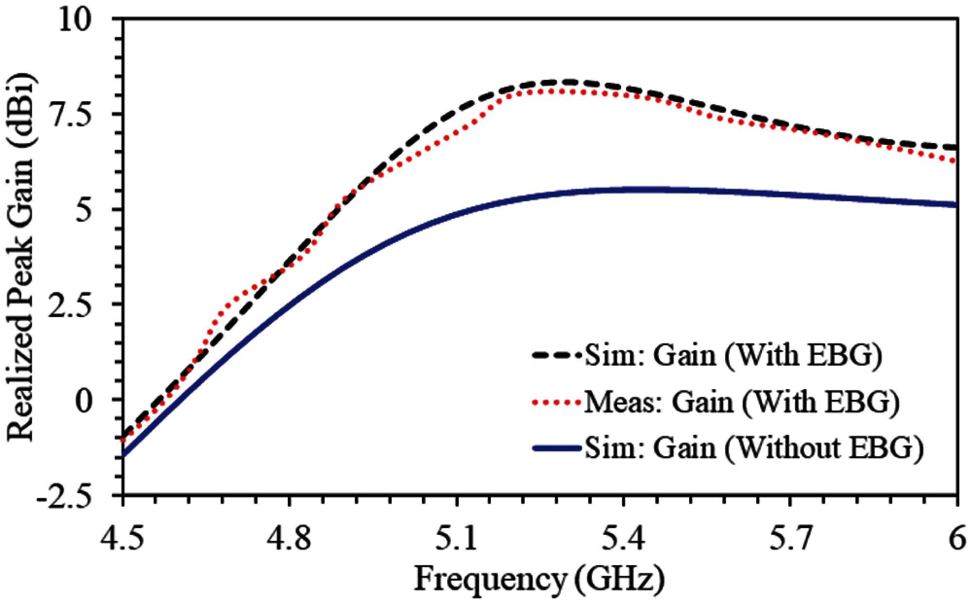
Figure 8: Realized peak gains (simulated without EBG, simulated with EBG, and measured with EBG)
A compact, low profile, and high gain dielectric resonator antenna are proposed, fabricated, experimentally tested, and verified. The proposed antenna system has a cylindrical dielectric resonator antenna with a height of 9 mm and a radius of 6.35 mm as a radiating element. The proposed dielectric resonator antenna is sourced with a slot while the slot is excited with a rectangular microstrip transmission line. The microstrip transmission line is designed for a 50 Ω impedance to provide maximum power to the slot. As a result, the proposed antenna operates at 5.15 GHz with a 10-dB absolute bandwidth of 430 MHz (4.98 – 5.41 GHz). It is important to mention that the gain of the dielectric resonator antenna is enhanced by the introduction of an electromagnetic bandgap (EBG) structure. In fact, EBG units are placed below the antenna, which enhances the realized peak gain from 5.32 dBi to 8.36 dBi at 5.15 GHz. More specifically, a gain enhancement of 3.04 dB is observed with the introduction of the EBG array. This antenna has several good features such as high gain, compact size, large bandwidth, and lower losses which make it a suitable choice for long-range wireless communication systems.
Acknowledgement: The author would like to thank the Deanship of Scientific Research at Majmaah Universty, Kingdom of Saudi Arabia for supporting this work (R-2021-211).
Funding Statement: The authors received no specific funding for this study.
Conflicts of Interest: The authors declare no conflicts of interest.
1. R. K. Mongia and P. Bhartia, “Dielectric resonator antennas—a review and general design relations for resonant frequency and bandwidth,” International Journal of Microwave and Millimeter-Wave Computer-Aided Engineering, vol. 4, no. 3, pp. 230–247, 1994. [Google Scholar]
2. T. A. Denidni and R. Qinjiang, “Hybrid dielectric resonator antenna with radiating slot for dual-frequency operation,” IEEE Microwave and Guided Letters, vol. 3, pp. 321–323, 2004. [Google Scholar]
3. A. Petosa and A. Ittipiboon, “Dielectric resonator antennas: A historical review and the current state of the art,” IEEE Antennas and Propagation Magazine, vol. 52, no. 5, pp. 91–116, 2010. [Google Scholar]
4. N. A. Jan, S. H. Kiani, F. Muhammad, D. A. Sehrai, A. Iqbal et al., “V-shaped monopole antenna with chichena itzia inspired defected ground structure for UWB applications,” Computers, Materials & Continua, vol. 65, no. 1, pp. 19–32, 2020. [Google Scholar]
5. A. Iqbal, A. Smida, A. J. Alazemi, M. I. Waly, N. K. Mallat et al., “Wideband circularly polarized MIMO antenna for high data wearable biotelemetric devices,” IEEE Access, vol. 8, no. 2020, pp. 17935–17944, 2020. [Google Scholar]
6. S. Muhammad, J. J. Tiang, W. S. Kin, A. Iqbal, M. Alibakhshikenari et al., “Compact rectifier circuit design for harvesting gsm/900 ambient energy,” Electronics, vol. 9, no. 10, p. 1614, 2020. [Google Scholar]
7. A. Smida, A. Iqbal, A. J. Alazemi, M. I. Waly, R. Ghayoula et al., “Wideband wearable antenna for biomedical telemetry applications,” IEEE Access, vol. 8, no. 2020, pp. 15687–15694, 2020. [Google Scholar]
8. A. Iqbal, M. A. Selmi, L. F. Abdulrazak, O. A. Saraereh, N. K. Mallat et al., “A compact substrate integrated waveguide cavity-backed self-triplexing antenna,” IEEE Transactions on Circuits and Systems II: Express Briefs, vol. 67, no. 11, pp. 2362–2366, 2020. [Google Scholar]
9. A. Iqbal, A. Smida, O. A. Saraereh, Q. H. Alsafasfeh, N. K. Mallat et al., “Cylindrical dielectric resonator antenna-based sensors for liquid chemical detection,” Sensors, vol. 19, no. 5, pp. 1200–1209, 2019. [Google Scholar]
10. O. A. Saraereh and A. Iqbal, “Design of compact and miniaturize asymmetric SIR-dRA filter-antenna subsystem,” Journal of Electromagnetic Waves and Applications, vol. 30, no. 16, pp. 2174–2184, 2016. [Google Scholar]
11. A. Iqbal, M. I. Waly, A. Smida and N. K. Mallat, “Dielectric resonator antenna with reconfigurable polarization states,” IET Microwaves, Antennas & Propagation, vol. 15, no. 7, pp. 683–690, 2021. [Google Scholar]
12. A. Iqbal, A. J. Alazemi and N. K. Mallat, “Slot-dRA-based independent dual-band hybrid antenna for wearable biomedical devices,” IEEE Access, vol. 7, no. 2019, pp. 184029–184037, 2019. [Google Scholar]
13. A. Iqbal, A. Bouazizi, S. Kundu, I. Elfergani and J. Rodriguez, “Dielectric resonator antenna with top loaded parasitic strip elements for dual-band operation,” Microwave and Optical Technology Letters, vol. 61, no. 9, pp. 2134–2140, 2019. [Google Scholar]
14. Y. Hwang, Y. P. Zhang, K. M. Luk and K. Y. Chow, “Gain enhancement miniaturized rectangular dielectric resonator antenna,” Electronics Letters, vol. 33, no. 5, pp. 350–352, Feb. 1997. [Google Scholar]
15. K. W. Leung, K. Y. Chow, K. M. Luk and E. K. N. Yung, “Offset dual-disk dielectric resonator of very high permittivity,” Electronics Letters, vol. 32, no. 22, pp. 2038–2039, 1996. [Google Scholar]
16. K. M. Luk, K. W. Leung and K. Y. Chow, “Bandwidth and gain enhancement of a dielectric resonator antenna with the use of a stacking element,” Microwave and Optical Technology Letters, vol. 14, no. 4, pp. 215–21, 1997. [Google Scholar]
17. Nasimuddin and K. P. Esselle, “A low-profile compact microwave antenna with high gain and wide bandwidth,” IEEE Transactions on Antennas and Propagation, vol. 55, pp. 1880–1883, 2007. [Google Scholar]
18. Nasimuddin and K. P. Esselle, “Antenna with dielectric resonators and surface mounted horns for high gain and large bandwidth,” IET Microwaves Antennas & Propagation, vol. 1, no. 3, pp. 723–728, 2007. [Google Scholar]
19. R. Gonzalo, P. de Maagt and M. Sorolla, “Enhanced patch-antenna performance by suppressing surface waves using photonic-bandgap substrates,” IEEE Transactions on Microwave Theory and Techniques, vol. 47, pp. 2131–2138, 1999. [Google Scholar]
20. F. Yang and Y. Rahmat-Samii, “Microstrip antennas integrated with electromagnetic bandgap (EBG) structures: A low mutual coupling design for array applications,” IEEE Transactions on Antennas and Propagation, vol. 51, pp. 2936–2946, 2003. [Google Scholar]
21. N. Llombart, A. Neto, G. Gerini and P. De Maagt, “Planar circularly symmetric EBG structures for reducing surface waves in printed antennas,” IEEE Transactions on Antennas and Propagation, vol. 53, pp. 3210–3218, 2005. [Google Scholar]
22. D. Sievenpiper, L. Zhang, R. F. Jimenez Broas, N. G. Alexopoulos and E. Yablonovitch, “High-impedance electromagnetic surfaces with a forbidden frequency band,” IEEE Transactions on Microwave Theory and Techniques, vol. 47, pp. 2059–2074, 1999. [Google Scholar]
23. S. A. Omar, A. Iqbal, O. A. Saraereh and A. Basir, “An array of M-shaped vivaldi antennas for UWB applications,” Progress in Electromagnetics Research Letters, vol. 68, no. 2017, pp. 67–72, 2017. [Google Scholar]
24. A. Iqbal, M. Al-Hasan, I. B. Mabrouk and M. Nedil, “Compact SIW-based self-quadruplexing antenna for wearable transceivers,” IEEE Antennas and Wireless Propagation Letters, vol. 20, no. 1, pp. 118–122, 2021. [Google Scholar]
25. N. K. Mallat and A. Iqbal, “Multi-band printed antenna for portable wireless communication applications,” Progress in Electromagnetics Research Letters, vol. 84, no. 2019, pp. 39–46, 2019. [Google Scholar]
26. A. Iqbal and O. A. Saraereh, “A compact frequency reconfigurable monopole antenna for Wi-fi/WLAN applications,” Progress in Electromagnetics Research Letters, vol. 68, no. 2017, pp. 79–84, 2017. [Google Scholar]
27. A. Iqbal, A. Bouazizi, A. Smida, A. Basir and U. Naeem, “Low-profile dual-band antenna with on-demand beam switching capabilities,” IET Microwaves, Antennas & Propagation, vol. 14, no. 1, pp. 15–20, 2020. [Google Scholar]
28. A. Iqbal, A. Bouazizi, O. A. Saraereh, A. Basir and R. K. Gangwar, “Design of multiple band, meandered strips connected patch antenna,” Progress in Electromagnetics Research Letters, vol. 79, no. 2018, pp. 51–57, 2018. [Google Scholar]
 | This work is licensed under a Creative Commons Attribution 4.0 International License, which permits unrestricted use, distribution, and reproduction in any medium, provided the original work is properly cited. |