DOI:10.32604/cmc.2022.022041
| Computers, Materials & Continua DOI:10.32604/cmc.2022.022041 | |
| Article |
Ultra-Wideband Annular Ring Fed Rectangular Dielectric Resonator Antenna for Millimeter Wave 5G Applications
1Wireless Communication Center, School of Electrical Engineering, Universiti Teknologi Malaysia, Johor Bahru, 81310, Malaysia
2Department of Electrical Engineering, College of Engineering, Jouf University, Sakaka, Aljouf, 72388, Kingdom of Saudi Arabia
*Corresponding Author: Mohd. Haizal Jamaluddin. Email: haizal@fke.utm.my
Received: 26 July 2021; Accepted: 07 September 2021
Abstract: In this article an ultra-wideband rectangular Dielectric Resonator Antenna is designed for millimeter wave 5G frequency band applications. Indoor 5G communications require antenna system with wide bandwidth and high efficiency to enhance the throughput in the channel. To fulfill such requirements a Dielectric Resonator Antenna (DRA) is designed here which has achieved an ultra-wide bandwidth of 20.15% (22.32–27.56 GHz) which is 5.24 GHz of bandwidth centered at 26 GHz as resonating frequency. This covers the complete band 30 (24.3–27.5 GHz) of 5G spectrum. 26 and 28 GHz are considered as most popular frequencies in millimeter wave 5G communications. The aperture fed DRA designed here has also achieved an efficiency of 96 percentage with maximum radiation in the broadside direction (Phi = 0, Theta = 0). The measured gain of the DRA is 6.3 dB. The DRA designed here has dimensions of 0.25 λ0×0.22 λ0×0.12 λ0. under the characteristic's mode. The DRA is placed over a substrate with dimensions 0.5 λ0×0.5 λ0×0.02 λ0. A cross slot aperture has been made on the ground plane which is placed above to the substrate. Here a full ground plane is used to resonate the antenna and is of similar dimension to the substrate. A microstrip line with two concentric rings makes an annular feed structure is used to excite the DRA and is placed below the substrate. The DRA is excited here in characteristics mode TE1Y1 and is the only mode of excitation. The DRA is linearly polarized, and the characteristic mode of excitation is maintained with 50 Ohm input impedance of the antenna. The DRA also gives here a good difference between the co-pol and cross pol approximately 15 to 20 dB. This antenna is more suitable for 5G indoor applications in millimeter wave frequency band centered at 26 GHz.
Keywords: Dielectric resonator antenna; 5G; wideband; millimeter wave; aperture coupled; 26 GHz
The conventional cellular systems have constrained their operation to a very narrow range of radio wave frequencies which is ranging from several hundreds of MHz to a limited GHz. Approximately all the spectrum in the radio frequency band is occupied by streamlining the spectrum access, spectrum allocation, and regulatory policies. This can help the use of unlicensed frequency spectrums as small cells in a cell cluster for efficient utilization of bandwidth in the 5G spectrum [1,2]. Applications like Internet of Things (IOT), small cells, indoor Wi-Fi requires antenna systems which can support wireless channels with wider bandwidth, higher gain and higher efficiency. This makes real challenge for 5G outdoor cellular networks which considers small cells with 200 m cell radii, the attenuation in air and rain will be of little significance over such distances [2]. To support the tremendous demands in data traffic, millimeter wave communications, can use the massive unlicensed and unused bandwidth of the conventional licensed microwave bands which has drawn the attention in the industry of fifth generation (5G) mobile communications systems [3,4]. 5G antenna systems requires wideband, high efficiency and high gain characteristics. Dielectric Resonator Antennas are being used as most convenient antennas for millimeter wave frequency bands. Wide bandwidth, low metallic losses, and high efficiency are the key advantages of using a DRA [5]. The impedance bandwidth of a rectangular DRA is inversely proportional to its permittivity, because a wide bandwidth is achievable under the fundamental characteristics mode of the DRA using the analytical models of quality factor. The high Q (quality factor) factor of the DRA can be achievable using higher permittivity of DRA either equal to 10 or more. So it is also reasonable that a rectangular DRA can achieve the impedance bandwidth of 20 to 30 percent increasing its quality factor and its efficiency. The rectangular DRA has three degree of freedom in generating the conditions of mode degeneracy under its characteristics mode [6]. In rectangular DRA the three wave numbers offer three degrees of freedom compared to other shape as cylindrical and triangular [7]. Different shapes of DRA as referred in this article are studied and compared here with different permittivity values at millimeter wave frequency band from 24 to 36 GHz. A wide impedance bandwidth of 10 percent and above have been observed using different feed techniques such as strip line, aperture, and substrate integrated waveguide. Using this novel annular feed structure, we could be able to achieve an impedance bandwidth of 20.15 percent. The advantage of using a rectangular DRA is the bandwidth of the lower order modes of a DRA can be easily varied from a fraction of a percent to about 10% or more by the suitable choice of the dielectric constant of the resonator material [8,9]. Rectangular DRA offer an advantage over cylindrical and spherical dielectric resonators in that the resonant frequencies of the different modes can be chosen to be different from each other by properly choosing the three dimensions of the resonator. It is known that three TExyz modes (TExl1, TE1yl and TE11z) of a rectangular shaped DRA radiate like x, y and z directed magnetic dipoles respectively [10].
In this paper we have validated experimentally and theoretically a rectangular dielectric resonator antenna under its characteristic mode of propagation. Here the simulations of antenna design are carried out using high frequency structure simulator (HFSS) and the calculations for DRA dimensions are done using MATLAB. An evolution of the final antenna design is carried out using the antenna optimization process. The parametric study of different characteristics parameters has been carried out here. The Rectangular DRA is characterized by its aspect ratio which can be taken from its height “d” width “a” and length “b”. The ratio of b/d and b/a have been chosen independently and is optimized to resonate at the desired frequency. The DRA has been widely used in mm-wave systems for its advantages of low loss and small size, as well as low cost. The simulation environment is rightly maintained with perfect boundary conditions of electric field. The results of radiation pattern, reflection coefficient, gain and efficiency are shown in this paper.
A ECCOS-TOCK Hik ceramic type Dielectric Resonator Antenna with permittivity, ɛr = 10 and loss tangent 0.002 is placed on a substrate of Roger RT/Duroid 5880 with permittivity, ɛr = 2.2, loss tangent 0.0009 and thickness 0.254 mm. The ground plane is placed above to the substrate and a micro strip line annular feed is placed below the substrate. An aperture slot is made through the ground plane over which the DRA is placed. The slot dimensions are optimized to match with the input impedance. A cross slot is made on the ground plane centered at z = 0 over which the DRA is placed. The DRA is fixed on the substrate using a conductive adhesive glue. The DRA design specification is shown in Figs. 1a and 1b shows the fabricated DRA. Fig. 1c indicates the top view of the slot aperture and Fig. 1d shows the annular microstrip feed line.
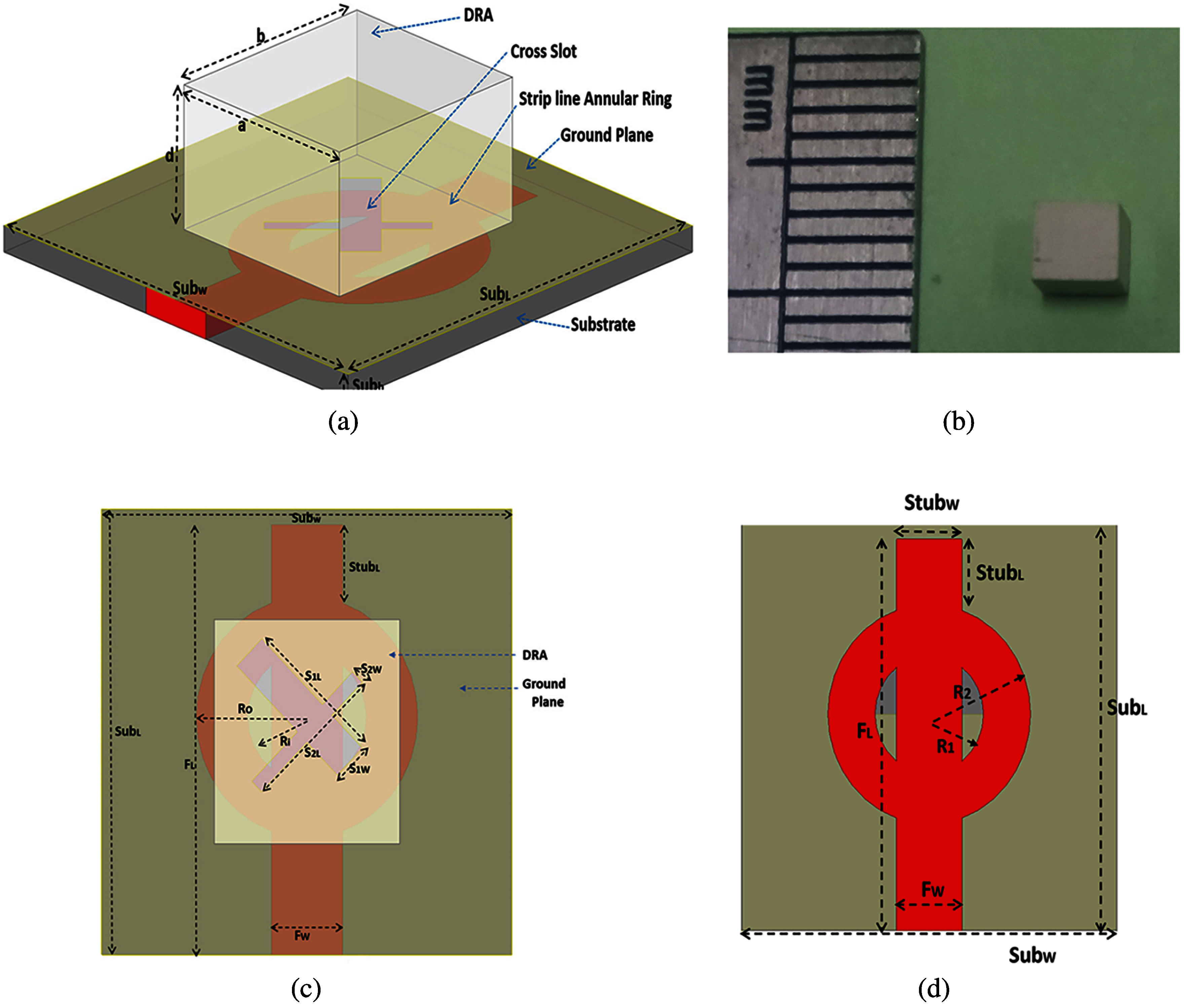
Figure 1: DRA design (a) 3D view of DRA fed by annular feed structure (b) Fabricated DRA (c) Top view showing the cross-slot dimensions (d) Bottom view showing micro strip annular feed structure
The dimensions of the DRA can be calculated using Eqs. (1) and (2). In a rectangular DRA there are three degrees of freedom so expressed in terms of three different coordinate axes. The DRA is placed over a ground plane where the slots have been made. Over a ground plane the DRA is generally excited under its characteristic's mode TEx, TEy and TEz. Fig. 2 shows the electric field distribution in XY plane and XZ plane.
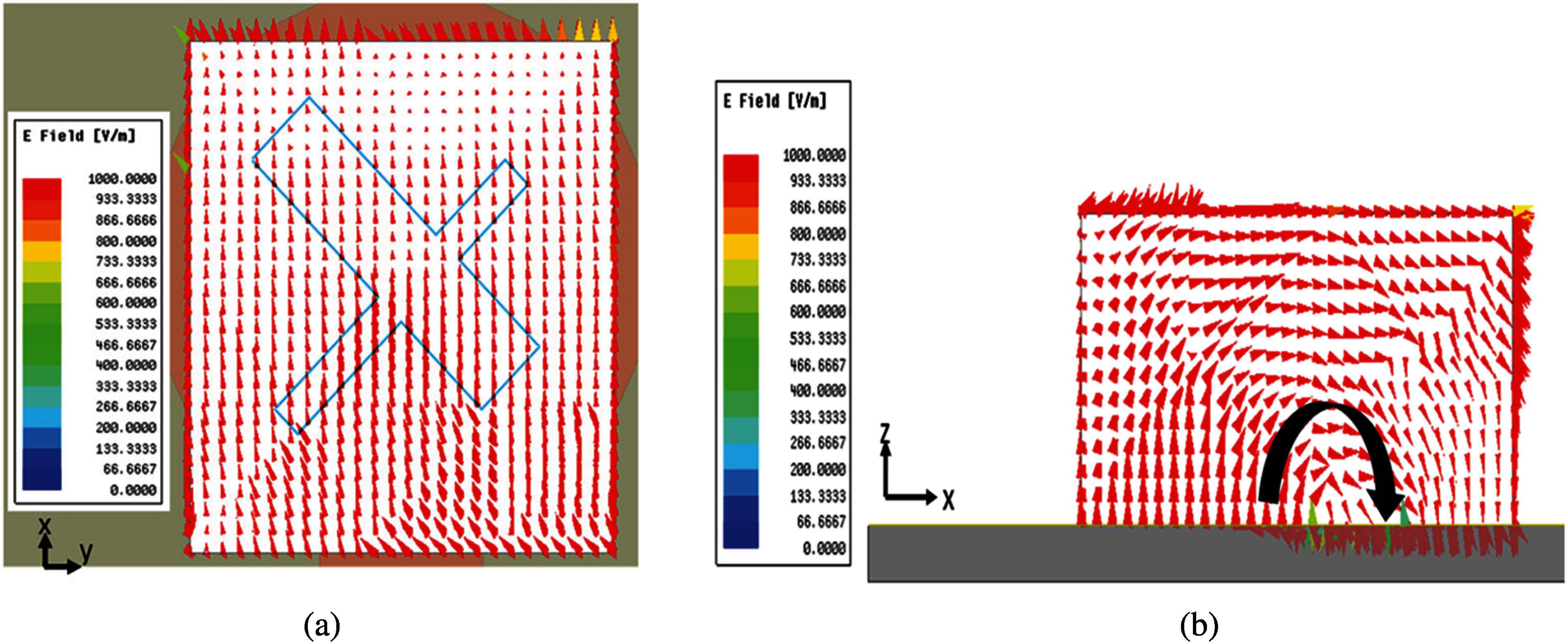
Figure 2: Electric field distribution over a) YZ plane b) XZ plane
The electric field components along each coordinate axes can be analyzed to find the mode of excitation in the DRA. Here the TE1Y1 mode has been excited whose resonant frequency can be calculated as mentioned in equations below.
Where
where a, b, d indicates the dimensions of the DRA which is proportional to the square root of the dielectric constant values of the Ceramic based DRA. Where c is the velocity of light in free space and f0 is operating resonant frequency. Aperture coupled technique helps for direct coupling of radiated fields over a transmission line to the DRA. The aperture coupling also supports the degree of freedom that a DRA optimizes with its dimensions. The high-quality factor value of DRA helps the dielectric resonator to store and uniformly distributed the electric fields. The design is compared with a simple rectangular slot fed DRA and performance results are investigated. The operating bandwidth of a DRA can be varied over a wide range by suitably choosing resonator parameters. The simulated electric field distribution showing the electric field density in XY and YZ plane is shown in Fig. 2. The DRA acts as a magnetic dipole under its characteristic's mode of radiation. The stub dimension of the strip line is optimized beyond the physical dimension of the DRA. The annular feed structure is prepared here from two concentric circle made at z = 0 in alignment with the microstrip feed line. The two concentric ring feed radius are optimized to get a maximum impedance bandwidth. The energy coupled from the strip line to the DRA depends upon the slot dimensions and the impedance match. The detail dimensions of DRA, micro strip feed and slot aperture are mentioned in Tab. 1. The dimensions of the slot have been optimized to obtain perfect impedance matching at the desired frequency. The slot length (SL) and slot width (SW) are calculated as
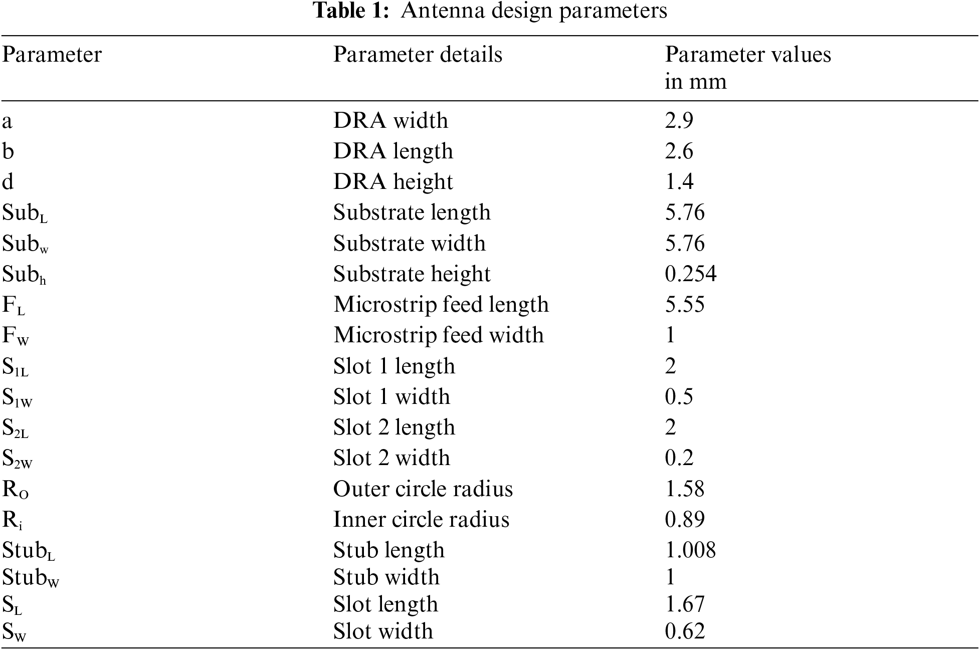
Slot Length,
Slot Width,
The aperture consists of the slot cut in the ground plane which is located at the center of the microstrip line. A narrow slot width is preferred in general to avoid generation of back lobe radiation component [11].
The stub extension S can be calculated as
where λg is guided wavelength in the substrate, which can be calculated as
where εeff is effective permittivity which can be calculated as
The calculated values of strip line length and width are shown in Tab. 1.
Where ɛr is permittivity of the substrate, h is height of the substrate, w is width of microstrip line.
2.1 Design Specifications for the DRA
A rectangular DRA has three degrees of freedom because of its 3D geometry. The aspect ratio and Quality factor (Q) of the DRA need to be investigated while designing the DRA. The calculated vales of aspect ratio are shown in Tab. 2. The Q factor with respect to the calculated a/h ratio is 35, Which is shown in Fig. 3. It is very high and can be achieved with DRA of higher permittivity. The dimensions of the stub are calculated using the effective permittivity values and in shown in Tab. 2. The stub dimension is an extension of feed line beyond the physical dimensions of the DRA. The DRA here is placed at z = 0 location and the stub length of the microstrip line is along the x direction. The chosen permittivity value of 10 is chosen for the DRA which generates a wide impedance bandwidth.
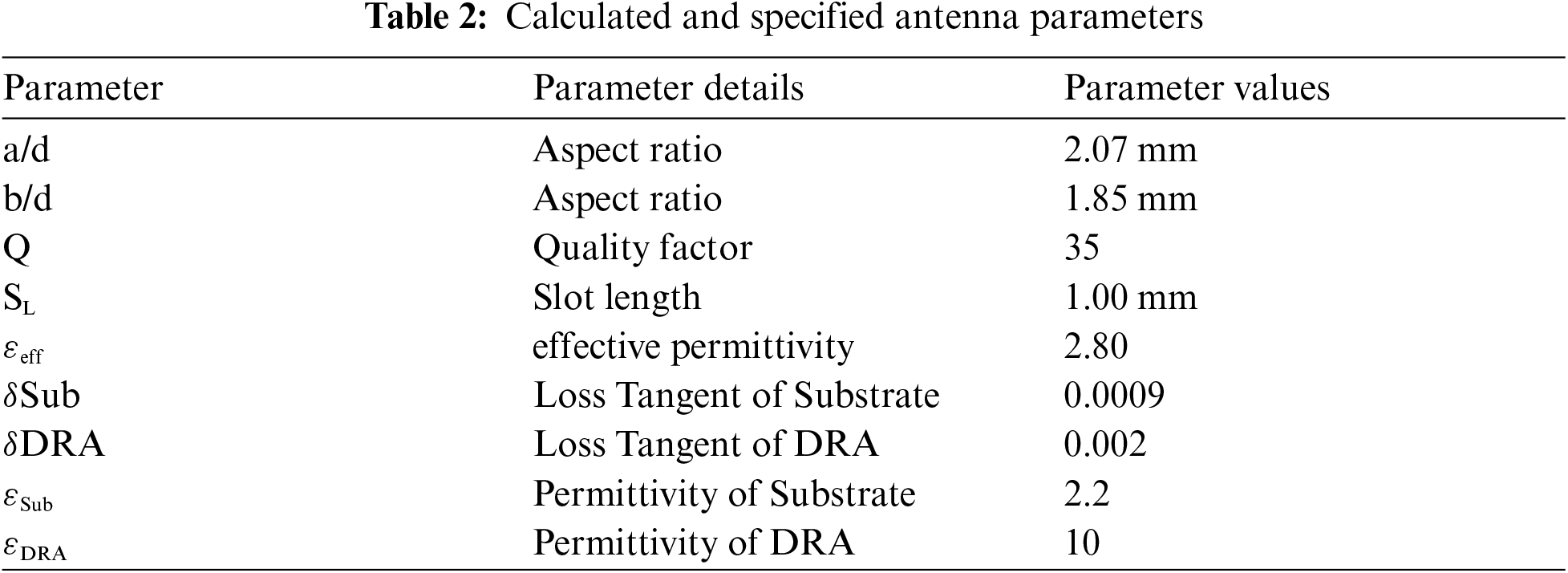
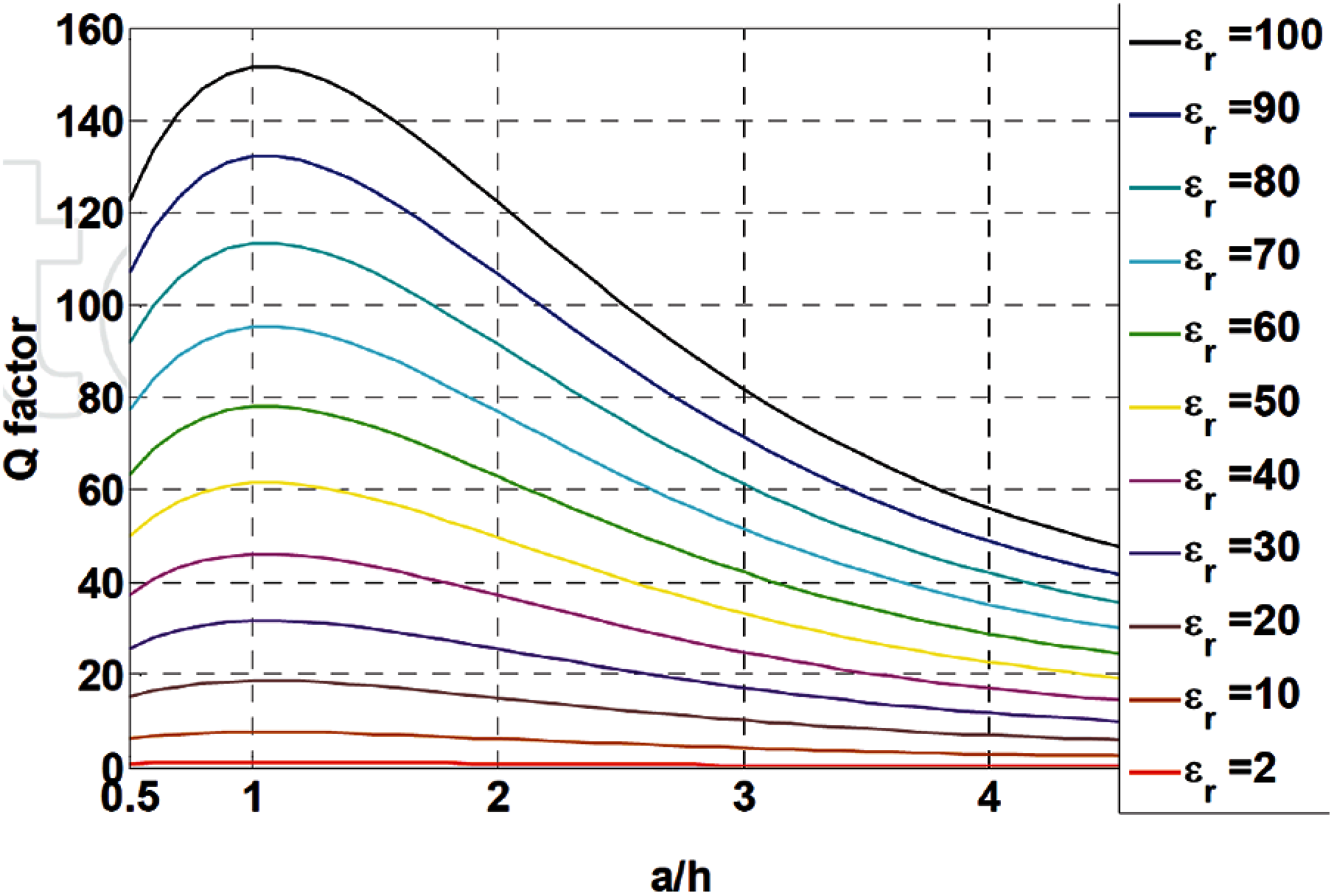
Figure 3: Q factor vs. aspect ratio for DRA [12]
2.2 Input Impedance of Cross Slot Fed DRA
The exact positioning of the aperture helps to achieve a large bandwidth in DRA. The amount of coupling depends upon the dimension of both slot and the strip line [13]. As the coupling depends upon the total Electric field distribution over the transmission line. Aperture-coupled DRA's may have advantages over coaxial probe-fed DRA's in terms of Band width and reduction of ohmic losses. The couple with the desired resonator mode, and to achieve a proper match with the source, the slot aperture must be properly adjusted. The distributed surface current can be controlled over the thickness of the dielectric substrate. As for millimeter waves the substrate dimensions are controlled to maintain the uniform field distribution and fringing fields. Here the slot dimensions and DRA matches with an ideal characteristics impedance of 50 Ohm which is shown in Fig. 4. There is a difference of 1 Ohm in Real and imaginary part at resonating frequency. This ideal impedance match helps in enhancing the radiation efficiency of the DRA as maximum power has been delivered to the DRA through the cross-slot aperture on the ground plane. The annular ring is prepared combining a second circular microstrip ring to the microstrip line.
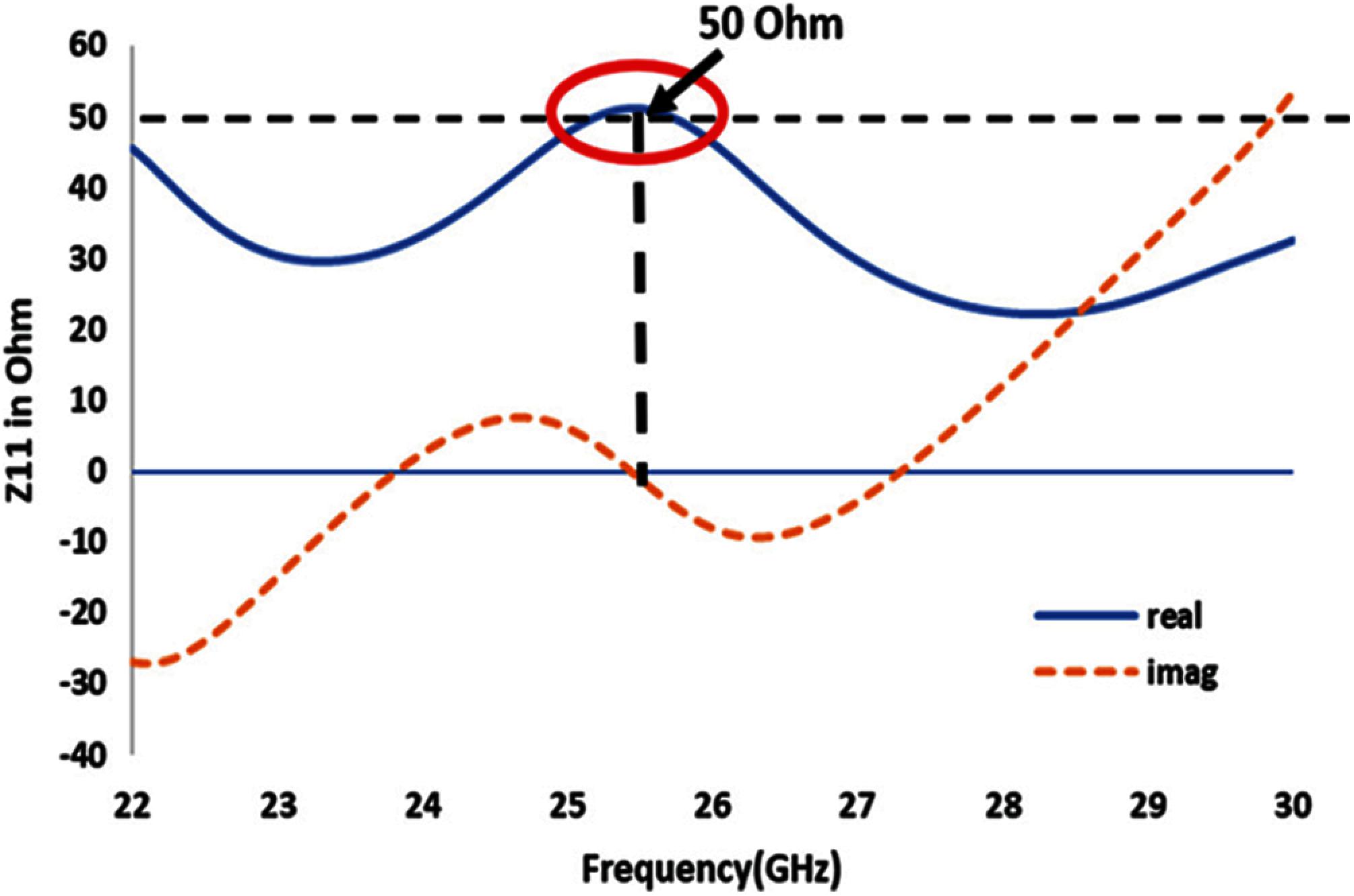
Figure 4: Input impedance of DRA vs. frequency (GHz)
The second and outer ring acts as higher frequency radiating element with minimum input impedance. Fig. 4 represents the input impedance of a cross slot aperture in ground plane, which is 50 ohm and is the characteristics impedance of DRA. It enhances the maximum power delivered to the antenna and so for enhancing the radiation efficiency of the DRA. The input impedance of the annular ring is very minimum as the distance of the outer ring is near to the feed location point. The input impedance of the circular ring is optimized to achieve the desired impedance bandwidth. The distribution of the surface current over the ring is analyzed with the ground plane placed above to the substrate. The measured fringing fields across the outer and inner radius of the circular ring are studied [14]. The surface current distribution over the annular feed structure is shown in Fig. 6. The electric field intensity is maximum near the feed port and is carried till the stub length of the micro strip line structure. Fig. 6 shows the current distribution over the annular feed structure and the ground plane. The filed intensity of surface current is maximum at the slot edges on the ground plane.
3 Evolution of Antenna Design and Parametric Analysis for Bandwidth and Gain Improvement
Fig. 8 shows the evolution of the antenna design from using a rectangular slot over annular feed structure to a cross slot over annular feed structure. The annular feed structure is used below the substrate and the ground plane is placed above to the substrate. The field intensity carried over the annular feed structure is shown in Figs. 6b and 6c. Both the rectangular and cross slot are matched with the characteristic's impedance of the antenna. There is shifting in resonance from 26.2 GHz (rectangular slot) to 25.4 GHz (cross slot) because of changing slot dimensions which is shown in Fig. 5. The respective variations in the input impedances are shown in Fig. 7. The varying field intensities from rectangular to cross slot aperture is shown in Figs. 8c and 8d. The DRA offers a higher efficiency of 96 percentage as the characteristic's impedance is matched with the required 50 Ohm input impedance.
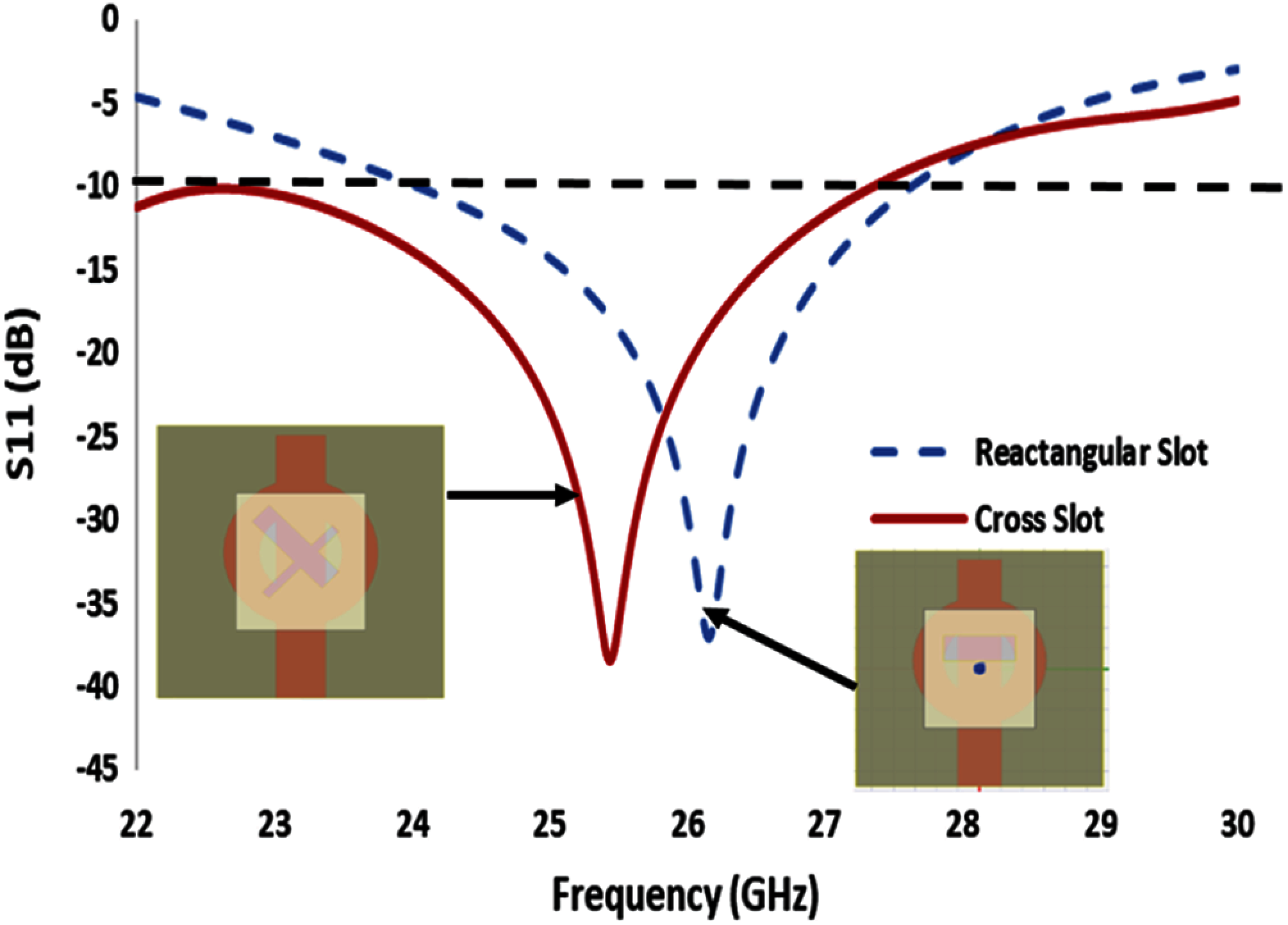
Figure 5: Simulated return loss of rectangular slot and cross slot of Dielectric resonator antenna

Figure 6: Electric field distribution (a) Field density over DRA (b) Current distribution in annular microstrip feed line (c) current distribution in ground plane
The evolution of antenna design here has been done in two steps. First a rectangular slot is made on the ground plane to feed the DRA. Then a cross slot aperture has been made on the ground plane. For both slot apertures the DRA is positioned at x = 0, y = 0 and z = 0 coordinates. The changing slot dimensions from the rectangular slot to cross slot changes the input impedance match of the antenna with respect to the ground plane. The imaginary part of the impedance varies over a range of 5 Ohm above or down to the zeroth axis line. The gain achieved using both the slot dimensions on the ground plane is shown in Fig. 10. The simulated broadside direction radiation over both E plane and H plane is shown in Fig. 9. There is little variation in gain over changing from rectangular slot to cross slot apertures but there is a wide shift in the resonating frequency from 26.2 to 25.4 GHz. The electric field distribution over the DRA excited by two different slot apertures on the ground plane makes the DRA to act like a magnetic dipole. The magnetic dipole moment depends on the coupling of fields from the annular feed structure to the DRA across the slots. The optimization of slot dimensions has been studied to get the desired impedance bandwidth. The simulated gain for both rectangular and cross slot is shown in Fig. 9, and the performance parameters of both the slot apertures are compared and shown in Tab. 3. The annular feed structure optimization for return loss is shown in Fig. 11.
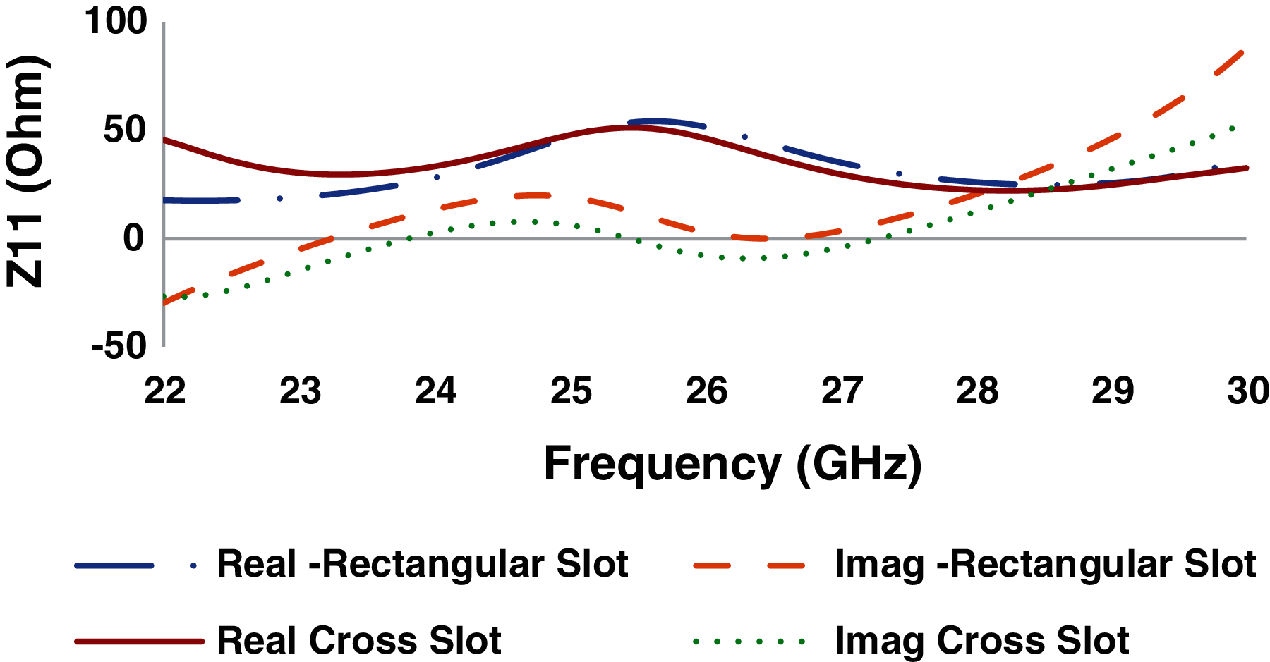
Figure 7: Input impedance of different slot aperture
The cross-slot aperture helps in encircling the fields with varying surface volume potentials of a DRA. The maximum radiation is along the broad side direction of the DRA. The impedance variation across the annular feed structure is shown in Fig. 11b. The two concentric circles were made with the microstrip line has a uniform real surface impedance across the structure. The selected height of the DRA from its optimization study of reflection coefficient is carried out which is shown in Fig. 12. The wider impedance bandwidth of 20.15 percentage has been achieved at this DRA height. The input impedance variation at different DRA height is shown in Fig. 13. The maximum variation of 60 Ohm is observed at DRA height of 1.1 mm. The selected DRA height of 1.4 mm has an input impedance of 50 Ohm which is the characteristics impedance of the DRA.
This variation in DRA height changes its mode of excitation, so an impedance tolerance of 10 Ohm to 15 Ohm needs to be tolerated. So here the mode TE1Y1 is excited at the selected DRA height. Only single mode is excited here in the DRA using both rectangular and cross slot on the ground plane. A bandwidth improvement of 1.64 GHz has been achieved while changing the ground plane slot from rectangular to cross slot, which is an improvement of 6.3 percent in impedance bandwidth. In the cross slot design the two rectangular slots inclined to each other are not of similar width and their length and width are also optimized to resonate the antenna. It is clearly visible in Fig. 13 that the load resistance offered at the connector mount on a pcb edge has good impedance matching with DRA height. So only it is excited under the fundamental mode of excitation.

Figure 8: Evolution of antenna design (a) Rectangular slot fed DRA (b) Cross slot fed DRA (c) surface current density of rectangular slot (d) Surface current density of cross slot
A minimum variation of 15 to 18 dB is observed between the co pol and cross pol power over the different annular feed dimensions. The performance improvement of the cross slot fed DRA is shown in Tab. 3. The low cross pol power has increased the broadside radiation of the DRA with a higher efficiency value. The simulated and measured value has a good resonance of the DRA at desired resonating frequency. The simulation results of DRA fed by both the rectangular and the cross slot has significant changes in gain, bandwidth while has similar mode of excitation.
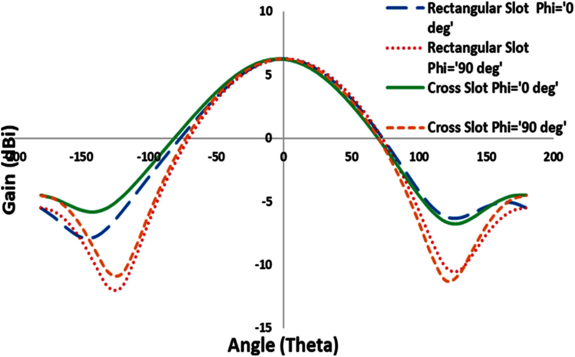
Figure 9: Gain vs. theta for different slot aperture
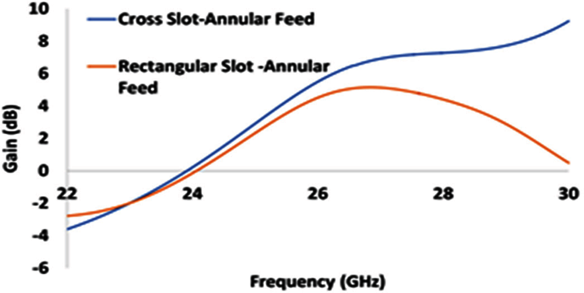
Figure 10: Gain vs. frequency for different slot aperture
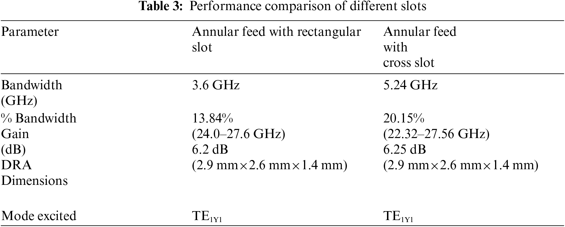
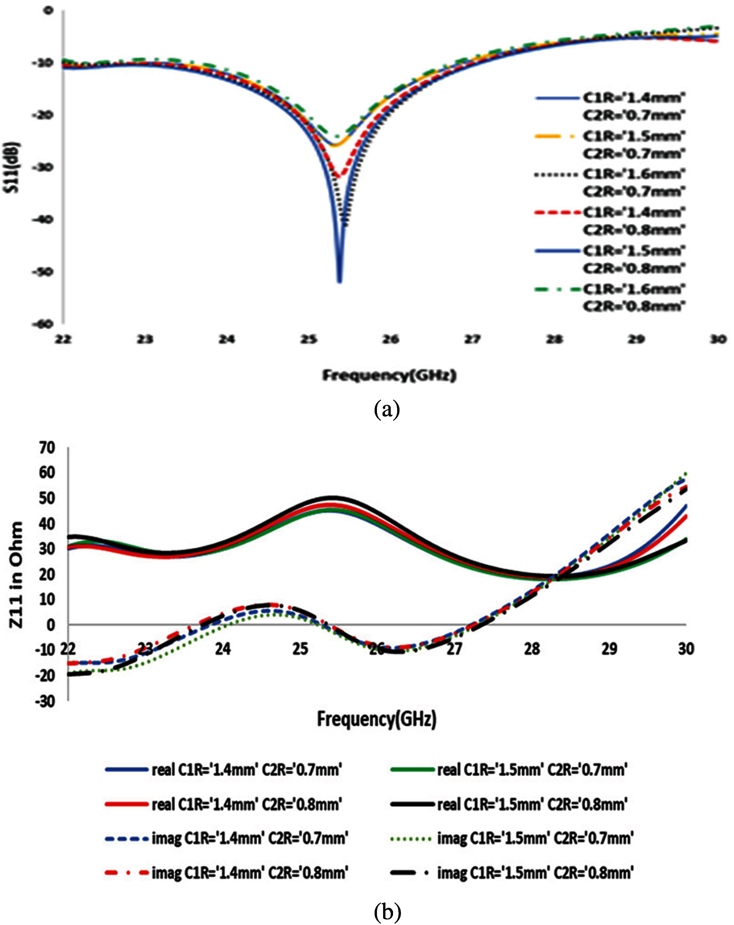
Figure 11: Annular feed structure performance (a) Reflection coefficient (dB) vs. frequency (GHz) at different radius of circle C1R and C2R (b) Input impedance (ohm) at varying circle radius (mm)
The annular microstrip feed used here is able to feed the DRA with an impedance bandwidth of 20.15% centered at 26 GHz. The broadside direction radiation for E and H plane is achieved by coinciding the DRA position with the feed structure at z = 0. The annular feed structure is matched with the 50-ohm characteristics impedance of the antenna. There is a frequency shift from 25.4 to 26.1 GHz in the antenna resonance. The measured bandwidth of 5.24 GHz has been achieved at 26.1 GHz as the resonating frequency. This wide bandwidth covering the complete frequency band of 5G at millimeter wave. Fig. 14 shows the variation in the reflection coefficient.
The DRA designed here is excited in fundamental characteristics mode of TE1y1 with input impedance of 50 Ohm. The 50-Ohm impedance helps to match with the terminal impedance and the magnetic flux generated in the DRA. The cross-slot aperture made on the ground plane makes a potential difference across the slot apertures to allow the DRA act as a magnetic dipole. The fields radiated across the slot depend on the slot dimensions on the ground plane which further enhances the coupling to the DRA. The broadside direction radiation has maximum as the DRA is places at the center of the cross-slot aperture which is z = 0. The instability in the measured gain vs. frequency is considered due to the fabrication challenges and errors. Adhesive glue is used to fix the DRA over the ground plane. Appropriate marking was done on the ground plane for accurate positioning of the DRA on the ground plane. The connector soldering to the microstrip line was done using a precision microscope with tolerance of 0.05 mm. The adhesive glue helps to fix the DRA on the ground plane over the slots and to minimize air gap between the substrate and the DRA. The DRA with fabricated ground plane, cross slot aperture and microstrip annular feed design is shown in Fig. 15. The ground plane dimensions are 5.76 mm×5.76 mm and is placed on the other side of the feed, as the DRA is placed manually over the slot apertures; there are chances that the DRA may be fixed with wrong positioning coordinates. This uncertainty makes change in the radiation pattern and in the impedance bandwidth.
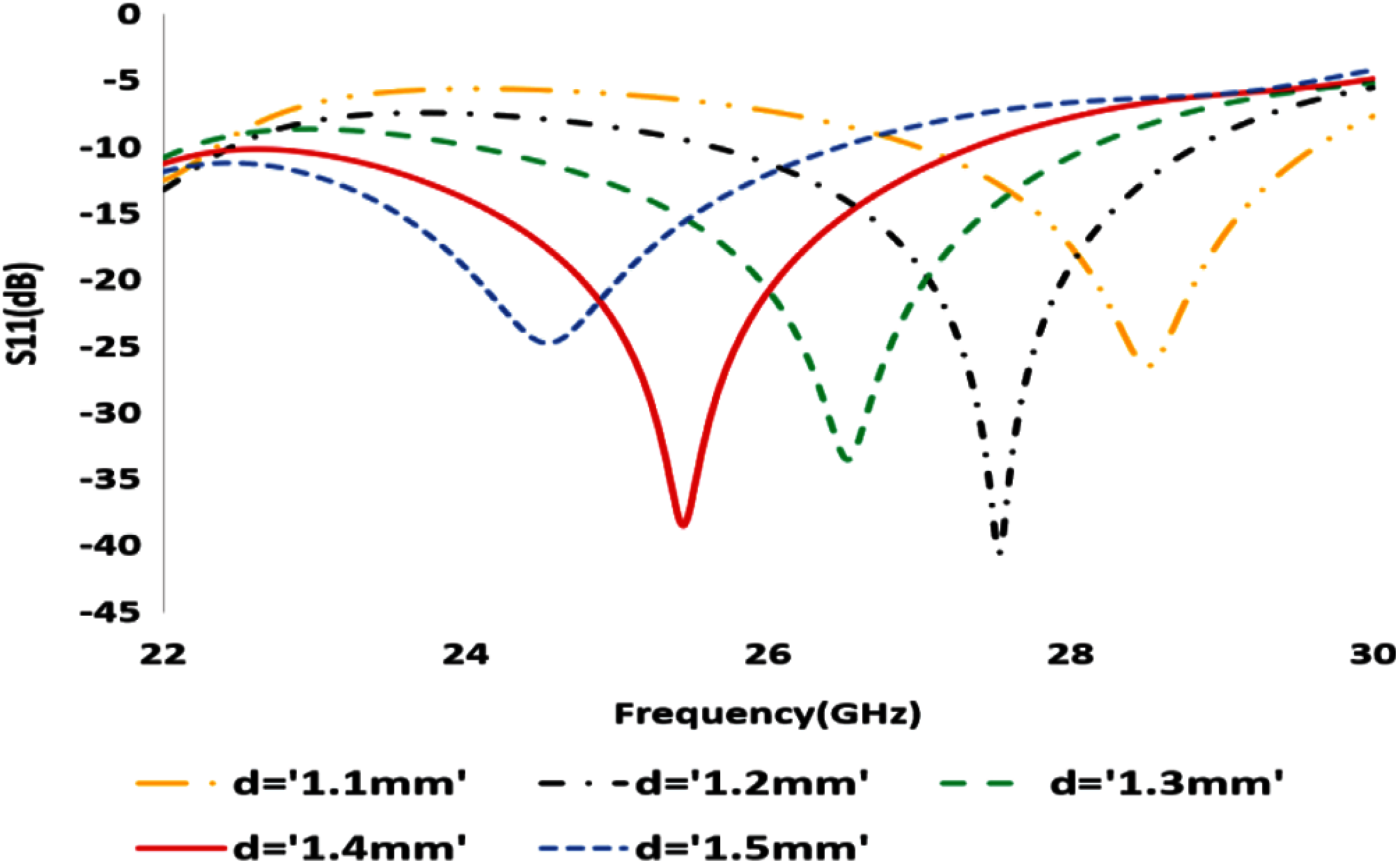
Figure 12: Reflection coefficient (dB) vs. frequency (GHz) at different height of DRA

Figure 13: Input impedance (Ohm) vs. frequency (GHz) at different circle radius C1R and C2R
The DRA excited under a fundamental mode here behaves as a magnetic dipole under a cross slot feeding technique. The cross-slot dimensions as are not uniform produces different potential difference across a metallic ground plane. As the ground plane is placed above to the substrate, the energy coupled to the DRA depends upon the cross-slot dimensions. The DRA positioning over the cross slot as is a manual technique, there caused few indifferences between the simulated and measured results of the antenna. The average gain of the DRA here ranges from 4 to 6 dB at different frequencies under resonance.

Figure 14: Reflection coefficient(dB) vs. frequency (GHz) for simulated and measured results of DRA

Figure 15: Fabricated annular microstrip line fed DRA (a) Bottom view of feed structure (b) Top view of cross slot aperture on ground plane (c) DRA with glue on ground plane (d) Top view of DRA (XY plane) (e) Measurement of DRA inside anechoic chamber
Fig. 16b shows the 3D radiation pattern of the DRA. The maximum radiation happens towards the broadside direction considering the position of the DRA over the ground plane and above the cross-slot apertures at z = 0. The maximum simulated gain observed in the 3D radiation pattern towards broadside direction (Phi = 0, Theta = 0) is 6.3 dB. The power radiated along the cross-pol radiation is minimized because of the cross-slot aperture on the ground plane. The variation in DRA efficiency along with the gain vales are due to the errors occur during the manual fabrication of the antenna. It can be shown in Fig. 16a both the efficiency and gain have a dip fluctional at around 27 GHz of frequency. A vector network analyzer was used to extract the reflection coefficient and the performance parameters as radiation pattern, gain was measured in the anechoic chamber.
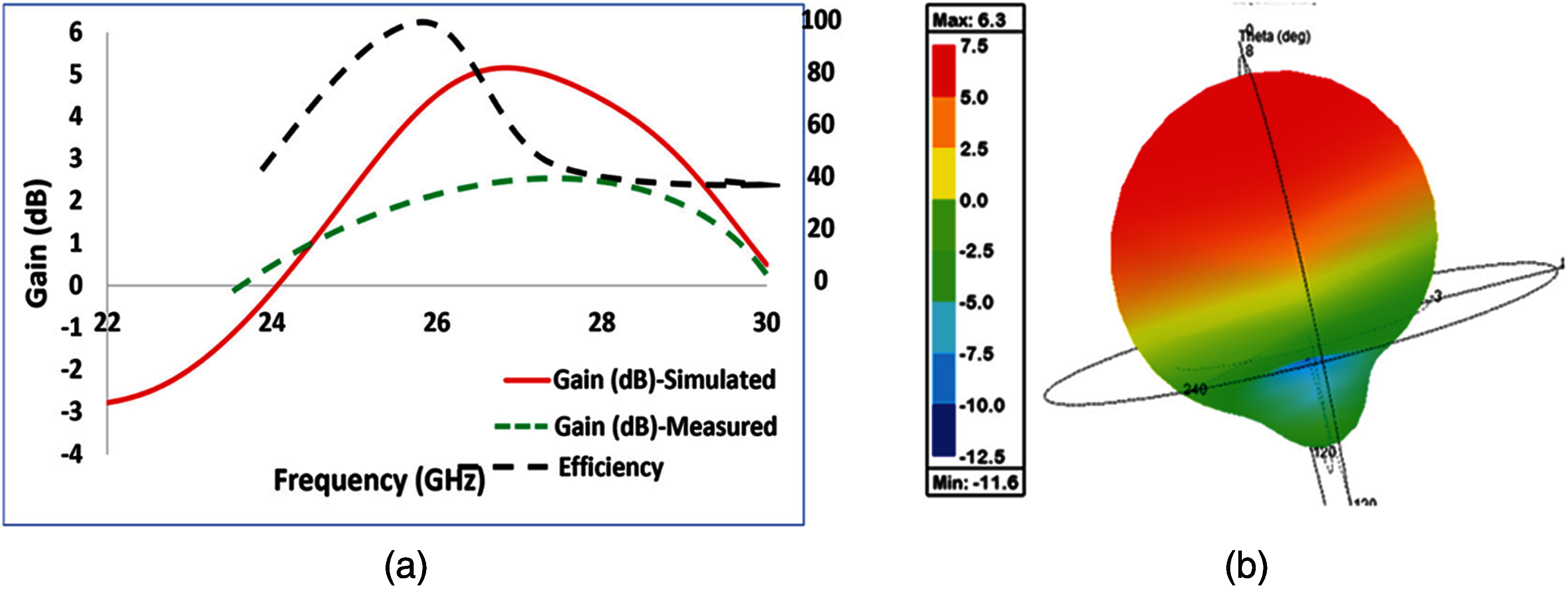
Figure 16: (a) Gain(dB) vs. frequency and efficiency (%) vs. frequency (b) 3D radiation plot
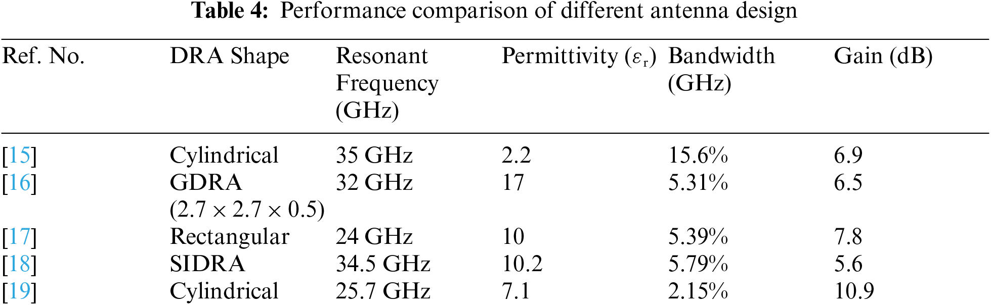
The measured and simulated broadside direction gain 6.3 and 5.4 dB respectively. Some uncertainties in the results were observed because of fabrication error. The radiation pattern in YZ and XZ plane are shown in Figs. 17a and 17b. The E field and H field variation along the cross pol in measurements has the least radiating power enhancing the efficiency of the DRA. The wide impedance bandwidth generated here is because of 50-ohm input impedance match with the microstrip line feed with annular structure. The DRA here is linearly polarized and excited with only in TE1Y1 mode, which is the characteristics mode of a rectangular DRA. Tab. 4 shows the performance of the DRA compared to the previous study. Singly fed DRA of different shapes and permittivity are studied and compared from 24 to 36 GHz of frequency band. Rectangular DRA with higher permittivity of 10 has achieved larger impedance bandwidth with an average gain value of 6 dB. As shown in Fig. 17 the measured cross pol for the cross slot fed DRA are quite larger value compared to simulated values both in the YZ plane and XZ plane. The gain simulated and measured were observed towards the broadside direction (theta = 0, phi = 0). So here using permittivity of 10 a wide bandwidth is achieved compared to other designs of DRA at millimeter wave frequency band.

Figure 17: Radiation pattern (a) XZ plane (b) YZ plane
The cross slot fed DRA proposed here has achieved a wide impedance bandwidth of 20.15 percentage with efficiency of 96 percentage and is linearly polarized with characteristics mode of TE1Y1. The wide impedance bandwidth of 5.24 GHz can cover the complete 5G band 30 GHz which is from 24.3 to 27.5 GHz. These characteristics make this antenna more suitable to be used for 5G indoor small cells applications. The measured gain of the DRA is 6.3 dB and is excited using mode TE1Y1.
Funding Statement: This work was supported by Universiti Teknologi Malaysia under TDR grant vote 05G20 and HiCOE grant vote 4J415.
Conflicts of Interest: The authors declare that they have no conflicts of interest to report regarding the present study.
Reference
1. D. Muirhead, M. A. L. I. Imran, S. Member, K. Arshad and S. Member, “A survey of the challenges, opportunities and use of multiple antennas in current and future 5G small cell base stations,” IEEE Access, vol. 4, pp. 2952–2964, 2016. [Google Scholar]
2. N. Bhushan, J. Li, D. Malladi, R. Gilmore, D. Brenner et al., “Network densification: The dominant theme for wireless evolution into 5G,” in IEEE Communications Magazine, vol. 52, no. 2, pp. 82–89, 2014. [Google Scholar]
3. W. Hong, Z. Jiang, C. Yu, J. Zhou, P. Chen, et al.,"Multibeam antenna technologies for 5G wireless communications,” in IEEE Transactions on Antennas and Propagation, vol. 65, no. 12, pp. 6231–6249, 2017. [Google Scholar]
4. Q. Li, Y. Zhang, J. Zhang, X. Ge and M. Guizani, “5G Millimeter-wave antenna array: Design and challenges,” IEEE Wireless Communications, vol. 24, no. 2, pp. 106–112, 2016. [Google Scholar]
5. A. Gaya, M. H. Jamaluddin, I. Ali and A. A. Althuwayb, “Circular patch fed rectangular dielectric resonator antenna with high gain and high efficiency for millimeter wave 5G small cell applications,” Sensors (Switzerland), vol. 21, no. 8, pp. 2694, 2021. [Google Scholar]
6. A. Petosa and A. Ittipiboon, “Dielectric resonator antennas: A historical review and the current state of the art,” in IEEE Antennas and Propagation Magazine, vol. 52, no. 5, pp. 91–116, 2010. [Google Scholar]
7. R. K. Mongia and A. Ittipiboon, "Theoretical and experimental investigations on rectangular dielectric resonator antennas,” in IEEE Transactions on Antennas and Propagation, vol. 45, no. 9, pp. 1348–1356, 1997. [Google Scholar]
8. R. K. Mongia and P. Bhartia, “Dielectric resonator antennas—A review and general design relations for resonant frequency and bandwidth,” International Journal of Microwave and Millimeter-Wave Computer-Aided Engineering, vol. 4, no. 3, pp. 230–247, 1994. [Google Scholar]
9. I. Ali, M. H. Jamaluddin, A. Gaya and H. A. Rahim, “A dielectric resonator antenna with enhanced gain and bandwidth for 5G applications,” Sensors (Switzerland), vol. 20, no. 3, pp. 675, 2020. [Google Scholar]
10. M. B. Oliver, R. K. Mongia and Y. M. M. Antar, A new broadband circularly polarized dielectric resonator antenna,” in IEEE Antennas and Propagation Society Int. Symposium, CA, USA, pp. 738–741, vol. 1, 1995. [Google Scholar]
11. A. Gaya, M. H. Jamaluddin, M. R. Kamarudin and I. Ali, “Design of wideband dielectric resonator antenna with aperture coupled technique for 5G applications,” in IEEE Int. RF and Microwave Conf. (RFMPenang, Malaysia, pp. 254–257, 2018. [Google Scholar]
12. S. Keyrouz and D. Caratelli, “Dielectric resonator antennas: Basic concepts, design guidelines, and recent developments at millimeter-wave frequencies,” International Journal of Antennas and Propagation, vol. 2016, pp. 1–20, 2016. [Google Scholar]
13. A. Gaya, M. H. Jamaluddin, M. R. Kamarudin and I. Ali, “A wideband dielectric resonator antenna with a cross slot aperture for 5G communications,” TELKOMNIKA, vol. 17, no. 5, pp. 2218–2225, 2019. [Google Scholar]
14. K. F. Lee and J. S. Dahele “Theory and experiment on the annular-ring microstrip antenna,”Annales des Telecommunications, vol. 40, pp. 508–515, 1985. [Google Scholar]
15. Q. Lai, G. Almpanis, C. Fumeaux, H. Benedickter and R. Vahldieck, “Comparison of the radiation efficiency for the dielectric resonator antenna and the microstrip antenna at Ka band,” IEEE Transactions on Antennas and Propagation, vol. 56, no. 11, pp. 3589–3592, 2008. [Google Scholar]
16. W. Mazhar, D. M. Klymyshyn, G. Wells, A. A. Qureshi, M. Jacobs et al., “Low-profile artificial grid dielectric resonator antenna arrays for mm-wave applications,” IEEE Transactions on Antennas and Propagation, vol. 67, no. 7, pp. 4406–4417, 2019. [Google Scholar]
17. Y. M. Pan, K. W. Leung and K. M. Luk, “Design of the millimeter-wave rectangular dielectric resonator antenna using a higher-order mode,” IEEE Transactions on Antennas Propagation, vol. 59, no. 8, pp. 2780–2788, 2011. [Google Scholar]
18. K. Gong, X. H. Hu, P. Hu, B. J. Deng and Y. C. Tu, “A series-fed linear substrate-integrated dielectric resonator antenna array for millimeter-wave applications,” International Journal of Antennas and Propagation, vol. 2018, pp. 1–7, 2018. [Google Scholar]
19. M. Mrnka, M. Cupal, Z. Raida, A. Pietrikova and D. Kocur, “Millimetre-wave dielectric resonator antenna array based on directive LTCC elements,” IET Microwaves, Antennas & Propagation, vol. 12, no. 5, pp. 662–667, 2018. [Google Scholar]
20. Y. Zhang, J. Y. Deng, M. J. Li, D. Sun and L. X. Guo, “A mimo dielectric resonator antenna with improved isolation for 5G mm-wave applications,” IEEE Antennas Wireless Propagation Letters, vol. 18, no. 4, pp. 747–751, 2019. [Google Scholar]
21. H. Chu and Y. Guo, “A novel approach for millimeter-wave dielectric resonator antenna array designs by using the substrate integrated technology,” in IEEE Transactions on Antennas and Propagation, vol. 65, no. 2, pp. 909–914, 2017. [Google Scholar]
22. A. Gaya, M. H. Jamaluddin and A. A. Althuwayb, “Wideband millimeter wave rectangular dielectric resonator antenna with annular feed structure for 5G applications,” in IEEE Int. RF and Microwave Conf. (RFMKuala Lumpur, Malaysia, pp. 1–4, 2020. [Google Scholar]
 | This work is licensed under a Creative Commons Attribution 4.0 International License, which permits unrestricted use, distribution, and reproduction in any medium, provided the original work is properly cited. |