DOI:10.32604/cmc.2022.021724
| Computers, Materials & Continua DOI:10.32604/cmc.2022.021724 | |
| Article |
Beamforming Performance Analysis of Millimeter-Wave 5G Wireless Networks
Deparment of Electrical Engineering, Engineering Faculty, The Hashemite University, Zarqa, 13133, Jordan
*Corresponding Author: Omar A. Saraereh. Email: eloas2@hu.edu.jo
Received: 12 July 2021; Accepted: 13 August 2021
Abstract: With the rapid growth in the number of mobile devices and user connectivity, the demand for higher system capacity and improved quality-of-service is required. As the demand for high-speed wireless communication grows, numerous modulation techniques in the frequency, temporal, and spatial domains, such as orthogonal frequency division multiplexing (OFDM), time division multiple access (TDMA), space division multiple access (SDMA), and multiple-input multiple-output (MIMO), are being developed. Along with those approaches, electromagnetic waves’ orbital angular momentum (OAM) is attracting attention because it has the potential to boost the wireless communication capacity. Antenna electromagnetic radiation can be described by a sum of Eigen functions with unique eigenvalues, as is well known. In order to address such issues, the millimeter-wave (mmWave) communication is proposed which is considered as one of the potential technology for 5G wireless networks. The intrinsic feature of all electromagnetic waves is OAM. The OAM beams’ unique qualities have led to a slew of new uses. Broadband OAM generators, on the other hand, have gotten very little attention, especially in the mmWave frequency band. The use of OAM in conjunction with mmWave can reduce the beam power loss, enhance the received signal quality, and hence increase the system capacity. The transmitter and receiver antennas must be coaxial and parallel to achieve precise mode detection. The proposed mmWave integrated with OAM system model is discussed in this study. The channel model is created using the channel transition characteristics. The simulation results demonstrate that the proposed system model is a good way to boost the system capacity.
Keywords: Antennas; beamforming; radiation pattern; mmwave; optimization
With the explosive growth in the number of mobile devices, the demand for spectrum resources in wireless communications is rapidly increasing. According to Cisco's annual Internet forecast in 2017, the global data traffic will exceed 330 trillion terabytes in 2020, of which mobile devices will account for 73% of the total traffic [1–4]. How to greatly increase the capacity of the communication system to cope with the demand for traffic growth is imminent. However, the traditional use of spectrum resources below 3 GHz has become saturated, and the spectrum utilization rate has also become saturated [5]. Approaching Shannon's limit, it is a drop in the bucket to increase the system capacity only on the existing authorized frequency bands. Therefore, it is imperative to expand the new spectrum resources. The use of millimeter- wave (mmWave) frequency band communication can break through the bottleneck of the lack of available spectrum resources and meet the needs of future mobile data services [6–8]. At the same time, mmWave wireless communication technology has the advantages of extremely wide bandwidth and easy miniaturization. In addition, the 60 GHz mmWave also has the advantage of not requiring authorization [9–14]. Therefore, the millimeter-wave wireless communication technology is expected to become one of the key technologies of 5G communication, especially suitable for high-speed, large-capacity communication [15,16].
Although the mmWave frequency band provides abundant bandwidth resources, compared with the traditional frequency band, the ordinary plane electromagnetic wave has a very high path loss in this frequency band, which seriously affects the system capacity [17–21]. In recent years, the information carrying ability of electromagnetic waves with orbital angular momentum (OAM) (also known as vortex electromagnetic waves) exhibited in the mmWave frequency band due to the vortex shape of the wavefront has attracted more and more attention [22–25]. The phase function of the OAM is
Therefore, applying the OAM modal characteristics to wireless communication can theoretically achieve a higher transmission rate. In [35], the authors achieved a total transmission rate of 32 Gbit/s and a spectrum utilization rate of 16 bits/s/Hz in the 60 GHz mmWave frequency band under line-of-sight (LoS) conditions. The experimental results show that, performing OAM multiplexing communication in this frequency band can reduce the power loss during beam propagation, increase the transmission distance, and reduce the size of the transceiver. Reference [36] proposed a mmWave communication system based on the OAM spatial modulation, which has greatly improved the energy efficiency as compared with OAM-MIMO system and has better robustness to mmWave path attenuation.
The OAM mmWaves are distributed in a spiral shape, which makes it impossible to receive signal energy in the main direction like ordinary plane waves. If it is not received in a specific direction, a considerable part of the energy cannot be captured by the receiving end [37]. Limited by the energy radiation characteristics of the OAM wave, the authors in [38] pointed out for the first time that when the uniform circular array (UCA) at both ends of the transmitter and receiver is aligned with the concentric coaxial height, the OAM mmWave system can provide the same performance as the multiple input multiple output (MIMO) system. However, when there is a slight tilt angle between the transmitting and receiving antenna arrays, it will seriously affect the accuracy of the receiving end modal detection, and the performance of the OAM mmWave system will be seriously reduced. In [39], the authors used the channel model of MIMO to study the channel model and capacity of the OAM mmWave communication system when the angle is shifted, thus verifying the above results. However, in this model, the UCA's multi-antenna system is used to generate the OAM mmWaves. The analysis process is based on the traditional MIMO transmission model, which takes into account the path attenuation between the transmitting and receiving antenna elements, but does not involve multiple OAM mmWave signals. The establishment and analysis of the transmission model is also not applicable to other antenna systems that generate the OAM mmWaves. In addition, this method only models the channel when the transceiver antennas are coaxial but there is an angular offset. This model is not suitable for the scenario where the transceiver antennas are parallel and non-coaxial. Therefore, how to establish a more universal OAM mmWave system channel model has important research significance.
When the OAM is used for wireless communication transmission, once the channel environment is disturbed, the energy of the OAM mode will be transferred with a certain probability, and the crosstalk between the modes will occur. Reference [40] used light waves to conduct the experiments in a wireless environment, and obtained the energy distribution of the transition due to turbulence. Based on this modal transition characteristic, this paper models the signal at the receiving end as a superposition of OAM mmWave signals of different paths, and derives the distribution of modal migration under the lateral axis offset of the transceiver through theoretical analysis, and models the system channel as multiple discrete memoryless channel model.
The remaining of this paper is arranged as follows. Section 2 establishes the transmission model of the OAM mmWave communication system. Section 3 models the channel based on the modal migration characteristics of the OAM mmWave, and derives the lateral axis offset of the transmitter and receiver. Section 4 analyzes the simulation results. Finally, the conclusion and summarizes the full text.
The OAM mmWave system studied in this paper is shown in Fig. 1. It contains multiple transceiver antenna pairs for generating and receiving different OAM mmWave signals. Each link transmitting end transmits a single OAM mode, then there are multiple mutually orthogonal OAM modes in the system, which can increase the system capacity.
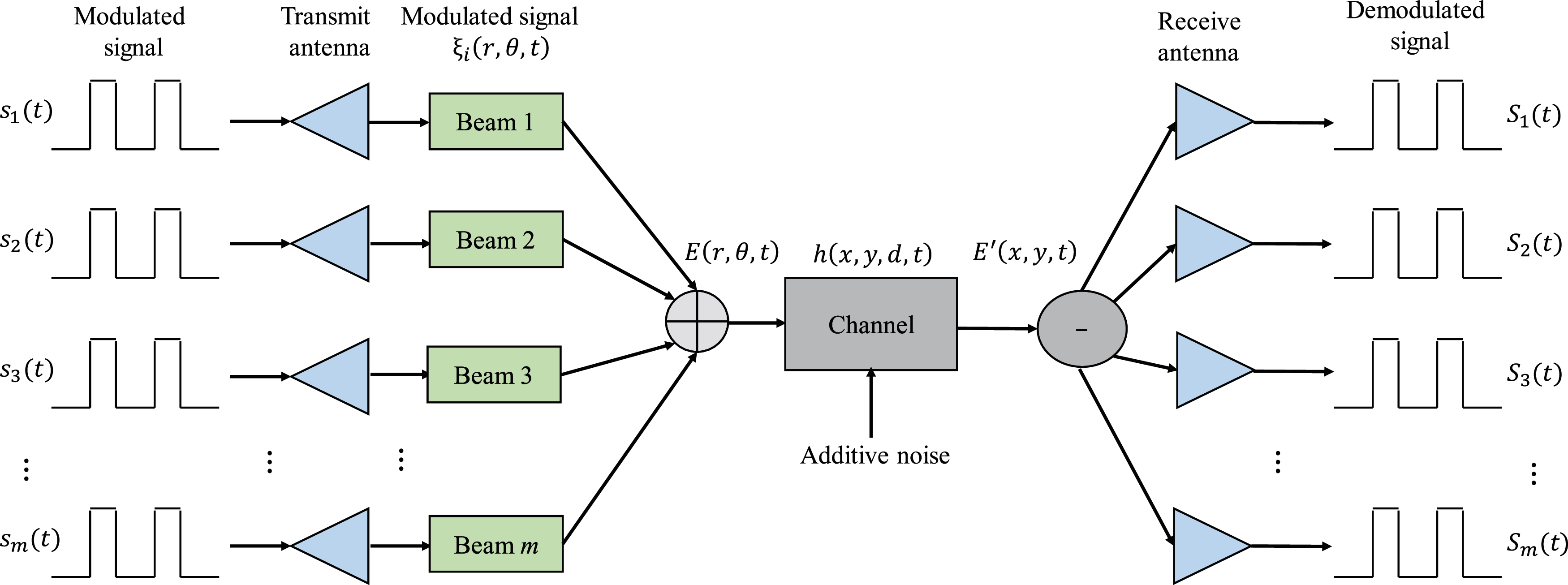
Figure 1: Proposed system model
Specifically, when a link is allocated to use mode
Among them,
where r and
where
The OAM mmWave modulated signal carrying data information at the transmitting end is
Among them, P is the transmission power of the system, and
In the OAM mmWave communication system, the signal at the receiving end may be affected by factors such as atmospheric turbulence, antenna gain, path attenuation, and additive noise. Its mathematical expression is the convolution of the transmitted signal and the transfer function.
where d represents the distance between the receiving and sending ends, that is, the path length.
where
3 Channel Modeling and Capacity Analysis
The OAM theoretically has an infinite number of orthogonal states, and we use this feature to establish multiple sub-channels between the transmitter and receiver for transmission. In the actual transmission process, additional consideration must be given to the modal transition caused by atmospheric turbulence and the offset of transmission and reception. Mode transfer means that during the transmission of OAM modes, the energy of a certain mode may be partly obtained by the transfer of other modes, and part of its own energy may also leak to other modes. At this time, although the signals received by the receiving end are still orthogonal to each other, they have produced varying degrees of distortion. That is to say, the original single-channel sub-channel transmission carries a single-mode OAM mmWave signal. Due to the influence of modal energy migration, the mmWave signal detected by the receiving end does not only carry the single-mode OAM, but with a certain The probability of taking a different modal value, which mistakenly restores it to a mmWave signal superimposed by multiple modalities. Therefore, in mathematical expression, the received distorted OAM mmWave signal can be regarded as the superposition of multiple mutually orthogonal OAM modes
Among them,
The modal migration of OAM in the case of lateral offset is shown in Fig. 2. In the case of no distortion, the signal transmitted by each sub-channel only contains a single OAM mode
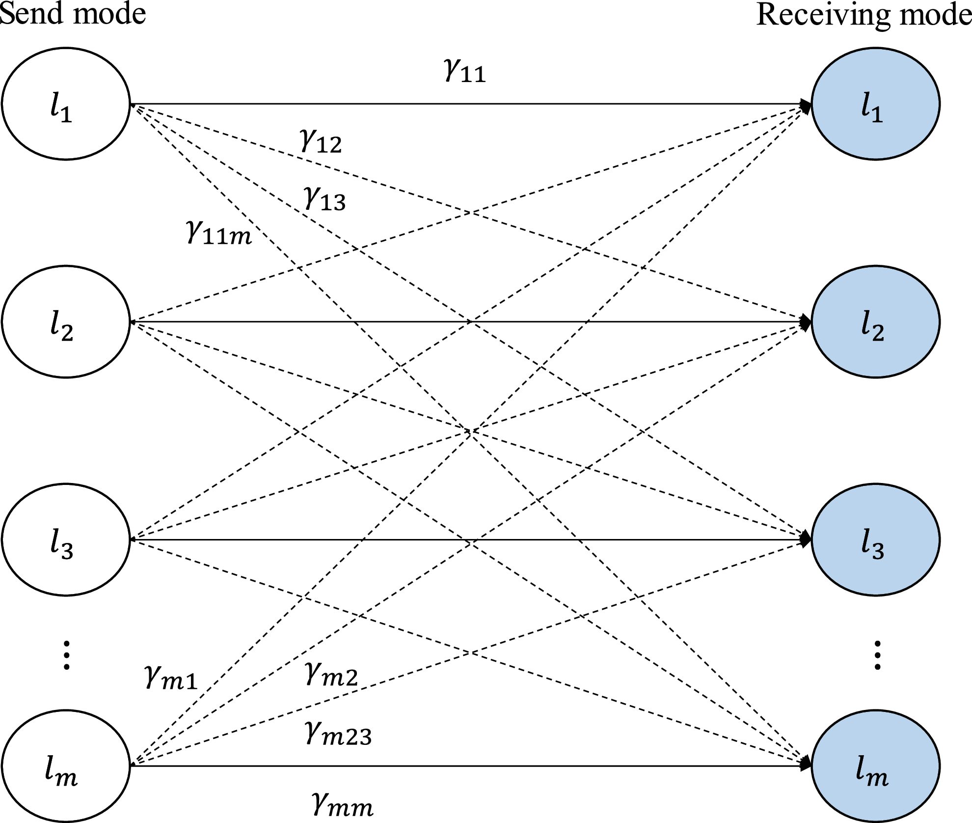
Figure 2: Illustration of transitions in energy
Channel characteristic coefficient, that is, the channel characteristic coefficient when the mode of the transmitting end is
Assuming that the entire system is in an atmospheric turbulence environment, the transmitter antenna generates mmWave signals with OAM mode, and the Laguerre Gaussian beam can be used to characterize the space and phase characteristics of the pure OAM mode mmWave, as shown in Eq. (3). Fig. 3 shows the geometric model of the transverse axis offset of the antennas at the receiving and transmitting ends in the Cartesian coordinate system. The coordinate origin O represents the antenna axis of the transmitting end, and the Z-axis represents the direction in which the beam axis points when the axis of the receiving end is aligned. The actual position of the axis of the receiving end is laterally shifted in the
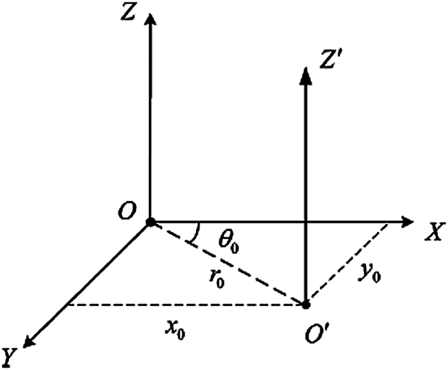
Figure 3: Tx-Rx antennas model in the coordinates
The expression of the transfer function
where B is the antenna gain coefficient,
In order to show the situation of the transceiver offset more intuitively, a set of polar coordinate parameters
Combining the above equation with Eq. (9), we can get the power correlation coefficient (distortion coefficient) between different modes at the receiving end as
This coefficient reflects the distribution characteristics of OAM modal migration. Further substituting Eqs. (2) and (7) into the integrand function expression in the above formula, the expression of
The channel characteristics are independent of the frequency and instantaneous phase of the modulation signal
In the same way, substituting Eq. (2) into the integrand in the above formula, the specific mathematical expression can be obtained
where
In order to derive the capacity of the OAM mmWave communication system, firstly, the channel matrix needs to be subjected to singular value decomposition (SVD). The specific expression is as follows
Both
In the previous part, we established a system model with m OAM modes at both the receiving and transmitting ends, so the final channel transmission matrix order is
The numerical results of the channel capacity of the OAM system under the given parameters are given below. In the simulation, it is assumed that the transmitting end power
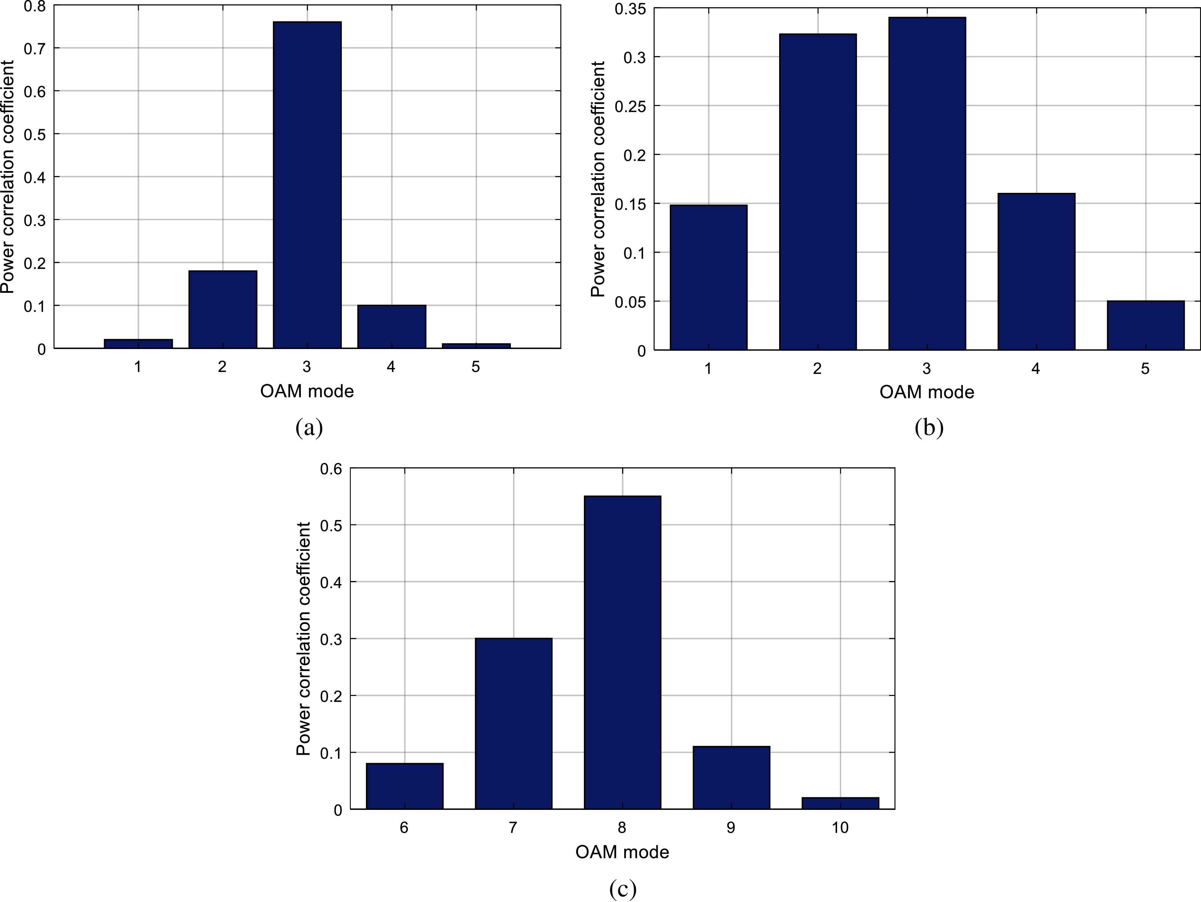
Figure 4: Comparison of power distribution (a)
As mentioned above, the physical meaning of the channel characteristic coefficient
Fig. 5 shows the curve of the capacity of the traditional MIMO mmWave system and the OAM mmWave system as a function of the signal-to-noise ratio (SNR) under the ideal channel. We can see that the capacity of the two systems increases with the increase of the signal-to-noise ratio. At the same time, under the same SNR, the capacity of a 4-mode OAM mmWave communication system is greater than that of a 4 × 4 MIMO (the number of transmitting antennas and receiving antennas are 4). The capacity of a 2-mode OAM mmWave communication system is greater than that of a 2 × 2 MIMO mmWave communication system. From this result, it can be seen that the performance of OM mmWave communication in terms of system transmission rate is better than the traditional MIMO mmWave system.
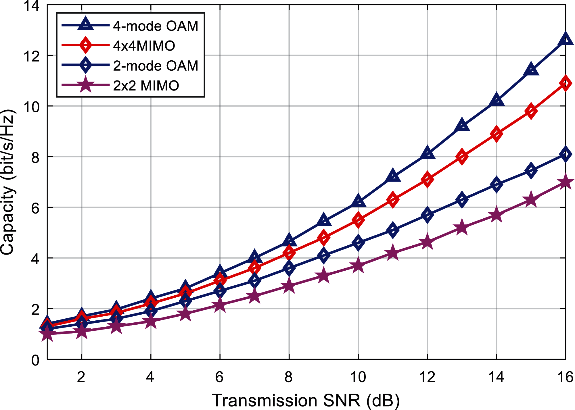
Figure 5: Capacity comparison of the proposed and existing algorithms
Fig. 6 shows the relationship between the system capacity and the transmission SNR for a given number of different modes. The selected 8-mode group is {l = 1, 2,…, 8}, and the 4-mode group is {l = 1, 2,…, 4}. It can be seen that for different modal numbers, the system capacity increases with the increase of the SNR, and the greater the number of modalities, the larger the system capacity. Set the offset distance to 1 mm. At this time, due to the transition and crosstalk between modes, the system capacity is significantly reduced. For example, when there is an offset, the system capacity of the 8-mode system is about 8.2 bits/s/Hz with a 15 dB SNR. This value is even smaller than the system capacity (about 12.6 bit/s/Hz) of the 4-mode system with the same SNR and no offset. Therefore, the lateral axis offset of the antennas at the receiving and transmitting ends will significantly reduce the performance of the OAM mmWave system. The alignment of the OAM mmWave transmission and reception is a problem that cannot be ignored.
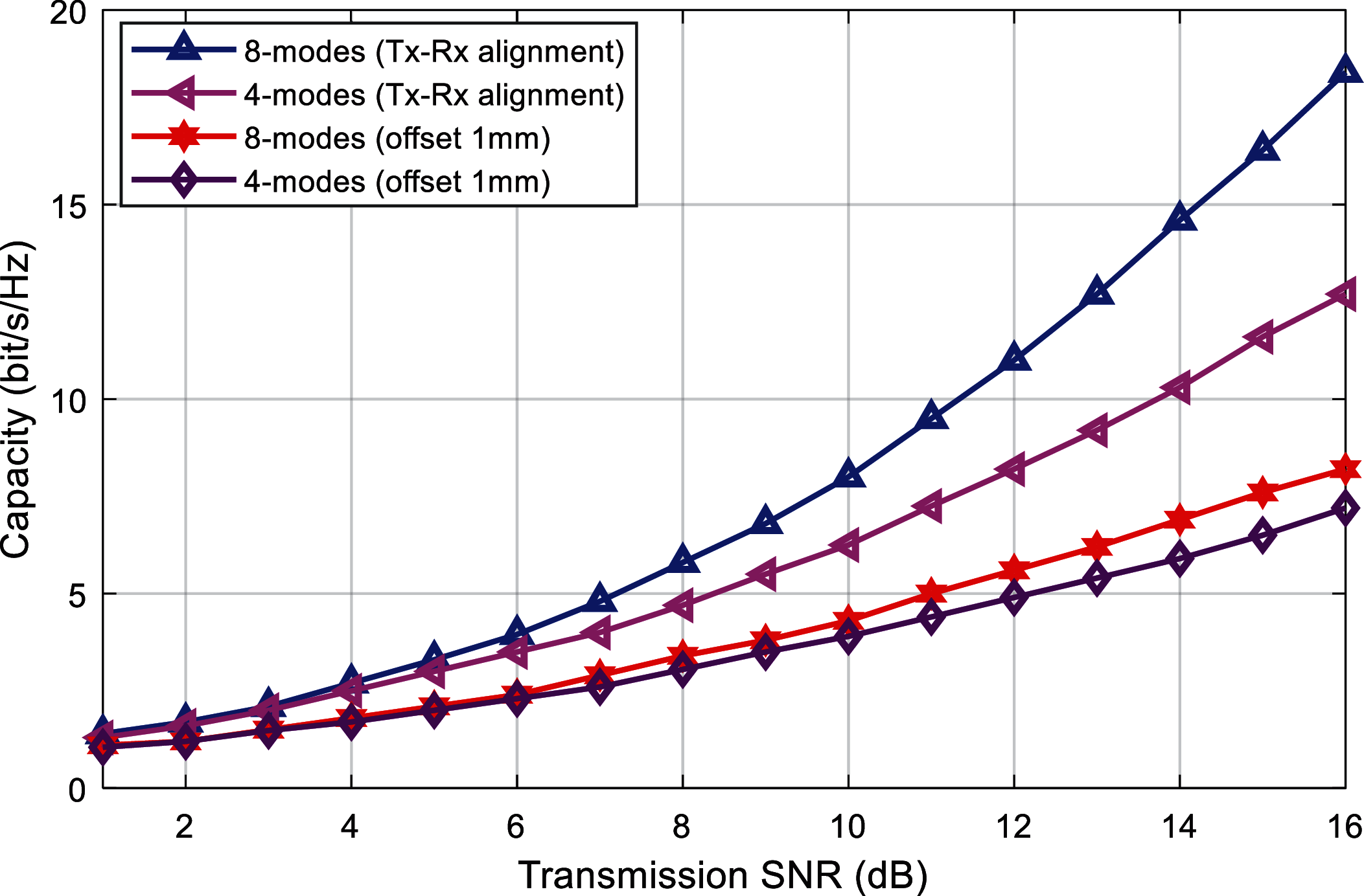
Figure 6: Capacity comparison in the on and off-axis alignment
Fig. 7 specifically depicts the specific relationship between the system capacity and the lateral offset distance under different number of modes. The given transmission SNR is 30 dB, and the selected 8-mode groups are {l = 1, 2 ,…, 8}, 4 modal group is {l = 1, 2, 3, 4}, and the 2 modal group is {l = 1, 2}. It can be found that with the increase of the lateral offset distance of the transmitting and receiving end, the probability of energy leakage between modes increases due to the modal migration, so the system capacity shows a significant decline trend. Taking the 8-mode as an example, when the lateral offset is 1 mm, the system capacity is about 24 bit/s/Hz, but when the lateral offset is increased to 5 mm, the capacity drops sharply to about 10 bit/s/Hz. It can be seen that the OAM is very sensitive to the lateral offset, and the existence of the lateral offset severely limits the performance of the OAM mmWave system. At the same time, when the offset reaches a certain distance, the system capacity will no longer decrease. This means that when the offset between the receiving and sending ends exceeds a certain limit, the interference distribution between modes will tend to a steady state, and the system capacity will no longer decrease. It is worth mentioning that when the offset distance is greater than 3 mm, the system capacity of the 8-mode and the 4-mode are both smaller than the system capacity of the 2-mode. This shows that the larger the number of modes, the more obvious the system performance will decrease as the offset distance increases. As there are more modes, the probability of modal migration is greater, and crosstalk between modes is more likely to occur.
Figs. 8 and 9 shows the relationship curve between the combination selection method of different modes and the system capacity. From the perspective of the system capacity, the power distribution of the OAM mode and the initial transmission mode and offset given in Fig. 4 are verified. Take the 4-mode group as an example, the given offset distance is 1 mm. In Fig. 8, three different OAM modal combination schemes are specifically considered with different mode intervals Δl respectively. The modal groups are {l = 1, 2, 3, 4}, {l = 1, 3, 5, 7}, {l = 1, 4, 7, 10}, and the corresponding modal interval is Δl = 1, 2, 3. From the simulation results, it can be found that under the same offset distance, the greater the modal interval, the lower the probability of energy leakage between modals, so the possibility of crosstalk between modals is reduced, and the system capacity is also greater.
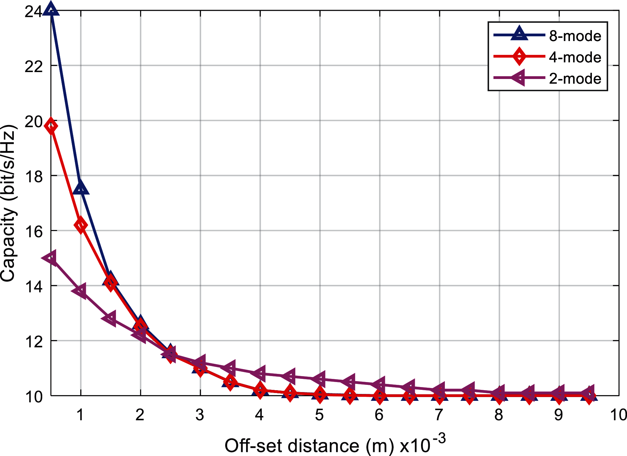
Figure 7: Comparison of capacity and offset distance for fixed SNR
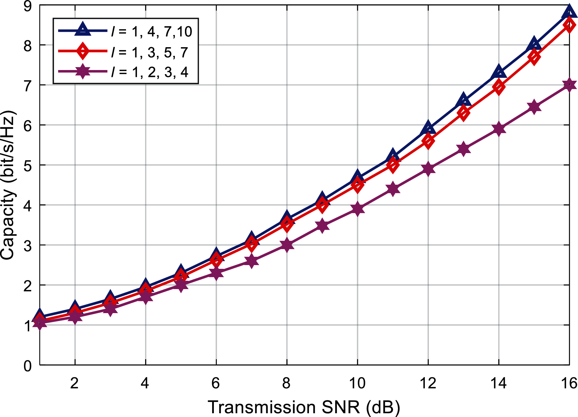
Figure 8: Capacity comparison against different modal intervals (
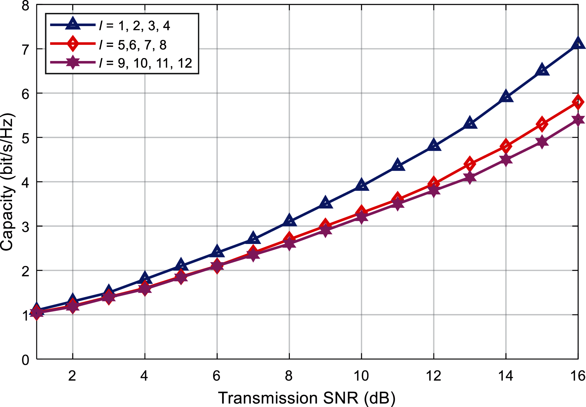
Figure 9: Capacity comparison with single modal interval
Fig. 9 depicts the relationship curve between different modal groups and system capacity when the modal interval is constant. Given the modal interval Δl = 1, the selected different modal groups {l = 1, 2, 3, 4}, {l = 5, 6, 7, 8}, {l = 9, 10, 11, 12}. It can be seen that, under the same offset distance, when the value of l is larger, the divergence of the OAM beam is stronger, and the energy transfer between modes is more serious at this time, so the system capacity is relatively small.
In summary, it is concluded that, the proposed method provides a feasible solution to solve the beamforming alignment problem with effective analysis and results. The results show that, the proposed technique provides improved results as compared with existing works which makes it a better candidate to be deployed in mmWave OAM environment.
In this paper, an OAM mmWave communication system is established, and for the situation that the antennas at both ends of the transceiver have a lateral axis offset when transmitting signals, combined with the modal migration characteristics of the OAM mmWave, the system is modeled and the theory is derived. The modal power distribution under the offset constructs the system channel transmission matrix. Based on the matrix, the system capacity is analyzed. The experimental simulation results show that the system capacity shows a downward trend as the offset distance increases, and eventually stabilize. The larger the number of modes, the more obvious the downward trend of system capacity. In addition, when transmitting and receiving offsets, when the system selects a modal group with a smaller modal value and a modal group with a larger modal interval, the system capacity is larger, that is, it is less affected by the offset at this time. This provides a feasible idea for improving the system capacity in the offset scenario. At the same time, future research work can also focus on the design of the axis offset calibration scheme to further optimize the system performance.
Acknowledgement: The authors would like to thank the editors and reviewers for their review and recommendations.
Funding Statement: The authors received no specific funding for this study.
Conflicts of Interest: The authors declare that they have no conflicts of interest to report regarding the present study.
1. R. A. Alhameed, I. Elfergani and J. Rodriguez, “Recent technical developments in energy-efficient 5G mobile cells: Present and future,” Computers, Electronics, vol. 9, no. 4, pp. 1–4, 2020. [Google Scholar]
2. S. L. Mohadmmed, M. H. Alsharif, S. K. Gharghan, I. Khan and M. Albreem, “Robust hybrid beamforming scheme for millimeter-wave massive mimo 5G wireless networks,” Symmetry, vol. 11, no. 11, pp. 1–18, 2019. [Google Scholar]
3. H. Zhang, B. Mao, Y. Han, Z. Wang, Y. Yue et al., “Generation of orbital angular momentum modes using fiber systems,” Applied Sciences, vol. 9, no. 5, pp. 1–17, 2019. [Google Scholar]
4. Z. Wang, J. Tu, S. Gao, Z. Li, C. Yu et al., “Transmission and generation of orbital angular momentum modes in optical fibers,” Photonics, vol. 8, no. 7, pp. 1–15, 2021. [Google Scholar]
5. C. H. Garcia, J. Vieira, J. T. Mendonca, L. Rego, J. S. Roman et al., “Generation and applications of extreme-ultraviolet vortices,” Photonics, vol. 4, no. 2, pp. 1–19, 2017. [Google Scholar]
6. A. M. Yao and M. J. Padgett, “Orbital angular momentum: Origins, behavior and applications,” Advances in Optics and Photonics, vol. 3, no. 2, pp. 161–204, 2011. [Google Scholar]
7. M. Liebmann, A. Treffer, M. Bock, U. Wallrabe and R. Grunwald, “Ultrashort vortex pulses with controlled spectral gouy rotation,” Applied Sciences, vol. 10, no. 12, pp. 1–13, 2020. [Google Scholar]
8. S. Alemaishat, O. A. Saraereh, I. Khan, S., H. Affes, X. Li et al., “An efficient precoding scheme for millimeter-wave massive mimo systems,” Electronics, vol. 8, no. 9, pp. 1–15, 2019. [Google Scholar]
9. O. A. Saraereh, I. Khan, B. M. Lee and A. Al-Bayati, “Modeling and analysis of wearable antennas,” Electronics, vol. 8, no. 1, pp. 1–12, 2018. [Google Scholar]
10. C. Wang, Y. Yao, J. Yu and X. Chen, “3d beam reconfigurable THz antenna with graphene-based high impedance surface,” Electronics, vol. 8, no. 11, pp. 1–21, 2019. [Google Scholar]
11. S. E. Hosseininejad, M. Neshat, R. Dana, M. Lemme, P. H. Bolivar et al., “Reconfigurable THz plasmonic antenna based on few-layer graphene with high radiation efficiency,” Nanomaterials, vol. 8, no. 8, pp. 1–18, 2018. [Google Scholar]
12. C. Lee and J. Jeong, “THz cmos on-chip antenna array using defected ground structure,” Electronics, vol. 9, no. 7, pp. 1–14, 2020. [Google Scholar]
13. F. Zhao, C. Zhu, W. Guo, J. Cong, C. Tee et al., “Resonant tunneling diode (RTD) terahertz active transmission line oscillator with graphene-plasma wave and two graphene antennas,” Electronics, vol. 8, no. 10, pp. 1–16, 2019. [Google Scholar]
14. S. Fajr, A. Rajawat and S. H. Gupta, “Design and optimization of THz antenna for onbody wban applications,” Optik, vol. 223, pp. 1–12, 2020. [Google Scholar]
15. S. Ullah, C. Ruan, T. Haq and X. Zhang, “High performance THz patch antenna using photonic band gap and defected ground structure,” Journal of Electromagnetic Waves and Applications, vol. 33, no. 15, pp. 1943–1954, 2019. [Google Scholar]
16. A. K. Geim and K. S. Novoselov, “The rise of graphene,” Nature Materials, vol. 6, no. 3, pp. 183–191, 2007. [Google Scholar]
17. J. Diaz and J. P. Carrier, “Microwave to THz properties of graphene and potential antenna applications,”“ in Ieee Int. Symp. on Antennas and Propagation (ISAPNagoya, Japan, pp. 239–242, 2012. [Google Scholar]
18. J. P. Carrier, M. Tamagone, J. G. Diaz and E. Carrasco, “Graphene antenna: Can integration and recofigurability compensate for the loss?,” in European Microwave Conf., Nuremberg, Germany, pp. 141–148, 2013. [Google Scholar]
19. X. Zhang, C. Ruan and J. Dai, “Reconfigurable antenna based on graphene at terahertz frequency,” in Progress in Electromagnetic Research Symposium (PIERSToyama, Japan, pp. 1–7, 2018. [Google Scholar]
20. M. Donelli, “A simple and efficient adaptive ISM-band antenna based on a reconfigurable optically driven parasitic structure,” Electronics, vol. 7, no. 2, pp. 1–13, 2018. [Google Scholar]
21. K. Payandehjoo and R. Abhari, “Investigation of parasitic elements for coupling reduction in multiantenna hand-set devices,” International Journal of RF and Microwave Computer-Aided Engineering, vol. 24, no. 1, pp. 1–10, 2014. [Google Scholar]
22. Z. Li, Z. Du, M. Takahashi and K. Saito, “Reducing mutual coupling of MIMO antennas with parasitic elements for mobile terminals,” IEEE Transactions on Antennas and Propagation, vol. 60, no. 2, pp. 473–481, 2012. [Google Scholar]
23. I. Nadeem and D. Y. Choi, “Study on mutual coupling reduction technique for MIMO antennas,” IEEE Access, vol. 7, pp. 563–586, 2018. [Google Scholar]
24. S. Y. Zhu, Y. L. Li, K. M. Luk and S. W. Pang, “Compact high-gain si-imprinted THz antenna for ultrahigh speed wireless communications,” IEEE Transactions on Antennas and Propagation, vol. 68, no. 8, pp. 5945–5954, 2020. [Google Scholar]
25. M. S. Rabbani and H. G. Shiraz, “Fabrication tolerance and gain improvements of microstrip patch antenna at terahertz frequencies,” Microwave and Optical Technology Letters, vol. 58, no. 8, pp. 1819–1824, 2016. [Google Scholar]
26. S. Anand, D. S. Kumar, R. J. Wu and M. Chavali, “Graphene nanoribbon based terahertz antenna on polyimide substrate,” Optk, vol. 125, no. 19, pp. 5546–5549, 2014. [Google Scholar]
27. V. P. Gusynin, S. G. Sharapov and J. P. Carbotte, “Magneto-optical conductivity in graphene,” Journal of Physics, vol. 19, no. 2, pp. 231–241, 2007. [Google Scholar]
28. L. A. Falkovsky and S. S. Pershoguba, “Optical far-infrared properties of a graphene monolayer and multilayer,” Physical Review B, vol. 76, no. 15, pp. 1–17, 2007. [Google Scholar]
29. Y. M. Lin, K. A. Jenkins, A. V. Garcia, J. P. Small, D. B. Farmer et al., “Operation of graphene transistors at gigahertz frequencies,” Nano Letters, vol. 9, no. 1, pp. 422–426, 2009. [Google Scholar]
30. G. W. Hanson, “Dyadic green's functions for an anisotropic, non-local model of biased graphene,” IEEE Transactions on Antennas and Propagation, vol. 56, no. 3, pp. 747–757, 2008. [Google Scholar]
31. L. A. Falkovsky and S. S. Pershoguba, “Optical far-infrared properties of a graphene monolayer and multilayer,” Physical Review B, vol. 76, no. 15, pp. 1–19, 2007. [Google Scholar]
32. V. Ryzhii, A. Satou and T. Otsuji, “Plasma waves in two-dimensional electron-hole system in gated graphene heterostructures,” Journal of Applied Physics, vol. 101, no. 2, pp. 667–673, 2007. [Google Scholar]
33. L. A. Falkovsky, “Unusual field and temperature dependence of the hall effect in graphene,” Physical Review B, vol. 75, no. 3, pp. 1073–1085, 2007. [Google Scholar]
34. Z. K. Liu, Y. N. Xie, L. Geng, K. Pan and S. Pan, “Scattering of circularly polarized terahertz waves on a graphene nanoantenna,” Chinese Physics Letters, vol. 33, no. 2, pp. 3341–3352, 2016. [Google Scholar]
35. Y. Yan, L. Li, Z. Zhao, G. Xie, Z. Wang et al., “32-Gbit/s 60-gHz mmWave wireless communication using orbital angular momentum and polarization multiplexing,” in IEEE Int. Conf. on Communications (ICCKuala Lampur, Malaysia, pp. 1–6, 2016. [Google Scholar]
36. X. Ge, R. Zi, X. Xiong, Q. Li and L. Wang, “Mmwave communications with OAM-sM scheme for future mobile networks,” IEEE Journal on Selected Areas in Communications, vol. 35, no. 9, pp. 2163–2177, 2017. [Google Scholar]
37. D. K. Nguyen, O. Pascal, J. Sokoloff, A. Chabory, B. Palacin et al., “Discussion about the link budget for electromagnetic wave with orbital angular momentum,” in European Conf. on Antennas & Propagation, The Hague, Netherlands, pp. 1117–1121, 2014. [Google Scholar]
38. A. Cagliero and R. Gaffoglio, “On the spectral efficiency limits of an OAM-based multiplexing scheme,” IEEE Antennas & Wireless Propagation Letters, vol. 16, no. 99, pp. 900–903, 2017. [Google Scholar]
39. N. Y. Zhang, W. Feng and N. Ge, “On the restriction of utilizing orbital angular momentum in radio communications,” in IEEE 8th Int. Conf. on Communications and Networking in China (CHINACOMGuilin, China, pp. 271–275, 2013. [Google Scholar]
40. S. M. Zhao, L. Wang, L. Zou, L. Gong, W. Cheng et al., “Both channel coding and wavefront correction on the turbulence mitigation of optical communication using orbital angular momentum multiplexing,” Optics Communications, vol. 376, no. 4, pp. 92–98, 2016. [Google Scholar]
 | This work is licensed under a Creative Commons Attribution 4.0 International License, which permits unrestricted use, distribution, and reproduction in any medium, provided the original work is properly cited. |