DOI:10.32604/cmc.2022.020870
| Computers, Materials & Continua DOI:10.32604/cmc.2022.020870 | |
| Article |
Handover Mechanism Based on Underwater Hybrid Software-Defined Modem in Advanced Diver Networks
1Department of Financial Information Security, Kookmin University, Seoul, 02707, Korea
2Special Communication & Convergence Service Research Center, Kookmin University, Seoul, 02707, Korea
3Department of Computer Science, Kookmin University, Seoul, 02707, Korea
*Corresponding Author: Soo-Hyun Park. Email: shpark21@kookmin.ac.kr
Received: 12 June 2021; Accepted: 27 July 2021
Abstract: For the past few decades, the internet of underwater things (IoUT) obtained a lot of attention in mobile aquatic applications such as oceanography, diver network monitoring, unmanned underwater exploration, underwater surveillance, location tracking system, etc. Most of the IoUT applications rely on acoustic medium. The current IoUT applications face difficulty in delivering a reliable communication system due to the various technical limitations of IoUT environment such as low data rate, attenuation, limited bandwidth, limited battery, limited memory, connectivity problem, etc. One of the significant applications of IoUT include monitoring underwater diver networks. In order to perform a reliable and energy-efficient communication system in the underwater diver networks, a smart underwater hybrid software-defined modem (UHSDM) for the mobile ad-hoc network was developed that is used for selecting the best channel/medium among acoustic, visible light communication (VLC), and infrared (IR) based on the criteria established within the system. However, due to the mobility of underwater divers, the developed UHSDM meets the challenges such as connectivity errors, frequent link failure, transmission delay caused by re-routing, etc. During emergency, the divers are most at the risk of survival. To deal with diver mobility, connectivity, energy efficiency, and reducing the latency in ADN, a handover mechanism based on pre-built UHSDM is proposed in this paper. This paper focuses on (1) design of UHSDM for ADN (2) propose the channel selection mechanism in UHSDM for selecting the best medium for handover and (3) propose handover protocol in ADN. The implementation result shows that the proposed mechanism can be used to find the new route for divers in advance and the latency can be reduced significantly. Additionally, this paper shows the real field experiment of air tests and underwater tests with various distances. This research will contribute much to the profit of researchers in underwater diver networks and underwater networks, for improving the quality of services (QoS) of underwater applications.
Keywords: Internet of underwater things (IoUT); underwater hybrid software-defined modem (UHSDM); advanced diver networks (ADN); channel selection mechanism (CSM); handover mechanism; acoustic; visible light communication (VLC); infrared (IR)
According to the recent survey made by the United States National Oceanic and Atmospheric Administration (NOAA), oceans cover 97% of the earth's surface with water [1]. Over the last few decades, IoUT plays a significant role in numerous applications such as oceanography, undersea exploration, environmental monitoring, tactical surveillance, deep-sea diver network monitoring, etc. as shown in Fig. 1 [2]. However, due to the characteristics of the underwater environment, the IoUT applications face several challenges. In [3,4], the drawbacks and comparison of communication technologies in IoUT such as acoustic, optical, radio frequency (RF), and magnetic induction (MI) are pointed out.
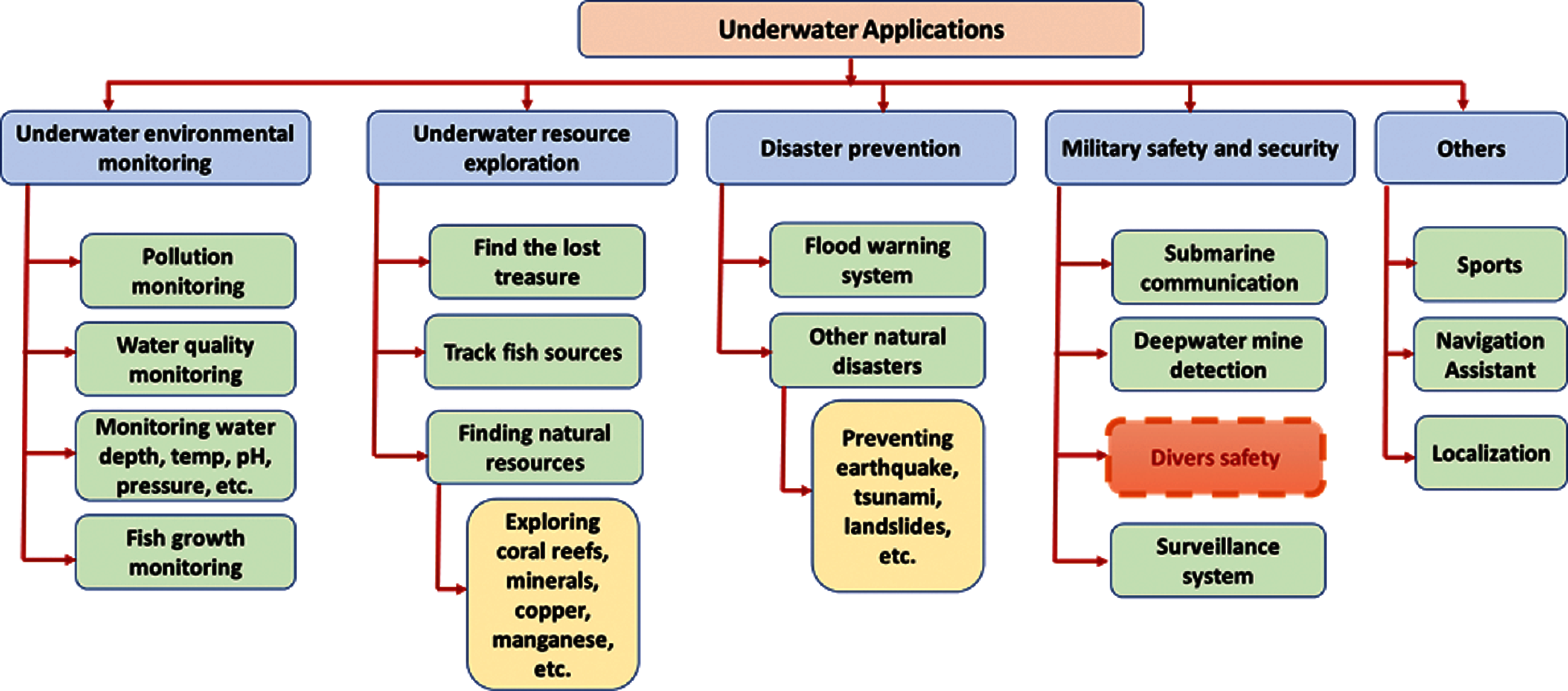
Figure 1: Classification of IoUT applications [2]
In IoUT communication technology, the sensor nodes are too deeply deployed underwater to perform the tasks based on the application that demand nodes to be mobile; for example, sensor nodes installed in an unmanned underwater vehicle (UUV), moves from place to place to monitor the underwater activities [5], In diver networks nodes moves from place to place to monitor the diver activities in case of emergency [6], In aquatic-based early warning system, the nodes change its position to notify the changes in the deep-sea environment [7], the mobile nodes notify the oil spills or pipe leakage during underwater oil extraction [8–11], etc. The major challenges of existing IoUT communication technologies are (1) issues in reliable data transmission (2) issues in link management or connectivity and (3) issues in energy-efficient data transmission [12]. In such cases, the UHSDM based handover mechanism is essential to support fast, energy-efficient, and reliable data transfer.
The existing system, problem statement, necessity of handover mechanism in IoUT mobile applications, and the necessity of UHSDM based handover mechanism in ADN are described below.
The existing handover mechanism was developed only for terrestrial area networks to support seamless communication in cellular networks. Majority of the research shows that the existing system was designed by considering the mobile users, vehicles, and other mobile devices in Long-Term Evolution-Advanced (LTE-A) [13–15]. However, the handover mechanism in the terrestrial environment cannot be applied to IoUT environment due to several limitations such as connectivity, low bandwidth, security, large propagation delay, node mobility error, localization, high energy consumption, memory limitation, re-routing issues, low data rate, etc.
Fig. 2 shows a scenario concerning mobility in ADN, here, two relay nodes RN1 and RN2 are connected with UHSDM based gateway (UGWs). i.e., UGW-1 and UGW-2, respectively. To deal with diver mobility, energy efficiency, and reduce the latency in UGW via the RNs, the underwater mobile node (MN) moves around in a random path that transmits information to survival. Owing to the random movement of MN, the time-changing distances between the underwater mobile node and underwater relay node are denoted by td1and td2. Also, the underwater mobile node has a fixed range or a threshold distance up to which it can communicate. Above the threshold distance, connection could not be established.
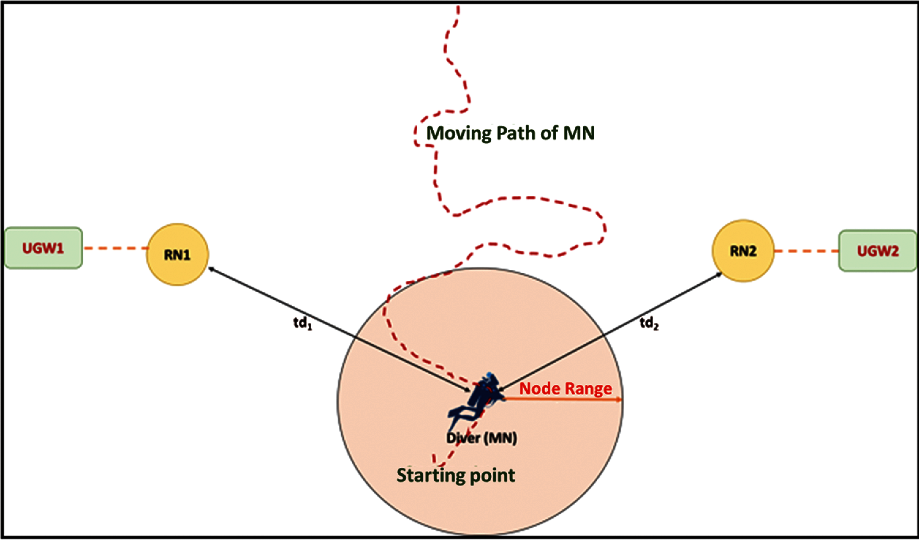
Figure 2: Node mobility scenario in ADN
The node mobility challenges in IoUT applications are listed below:
• Node mobility management: Due to the mobility of underwater sensor nodes, the device connectivity can be broken easily. This causes data loss while transferring data from underwater sensor nodes. Therefore, mobility management is necessary to monitor the activities of devices in IoUT environment.
• Topology management: The mobile nodes can change the topology based on the position. Hence, the IoUT applications face difficulty in routing.
• Memory management: The memory size is limited for all smart sensing devices in IoUT environment. The mobile nodes that collect huge amount of data from IoUT environment, makes memory management one of the significant challenges in mobile IoUT applications.
• Battery management: The load-balancing is an important task of intelligent sensing devices since there is only limited power backup for sensor nodes in IoUT environment. The mobile nodes also consume more power for moving, collecting, and transmitting data.
• Localization: In IoUT environment the bandwidth is limited, RF signals are very highly attenuated, and the sensor nodes are sparsely deployed. Therefore, applying the localization techniques of terrestrial wireless sensor networks such as global positioning systems (GPS) is not viable for the underwater environment [16].
• Data generation: In IoUT environment, huge quantity of data is currently being generated by underwater mobile nodes, underwater sensors nodes, and actuators for supporting various IoUT applications such as ADN, environmental monitoring, surveillance, etc.
• Huge data collection: The underwater sensor nodes generate a huge amount of data. Also, the data collection methods in underwater wireless sensor networks are significantly different from those in wireless sensor networks, due to high-level battery power consumption, high memory usage, and so on. Majority of the suggested schemes are even facing difficulties in underwater data collection [17]
• Optimization: The underwater nodes in the IoUT networks continuously generate a huge amount of data that directly affects the durability of connections in the underwater networks. Therefore, the power utilization of the underwater networks is important and must be optimized [18].
• Battery life prediction: The underwater wireless sensor networks and their radical computer processing abilities have enabled numerous IoUT applications to turn into the ensuing frontier, touching nearly all the realms of everyday life. With this huge progress, battery power optimization has become the major concern of senor nodes in IoUT environment [19].
• Routing: IoUT networks mostly uses acoustic or visible light signal for communication between the devices in underwater. This consumes extremely high energy for very long-range acoustic communication, and short-range visible light communication technology. Hence, the necessity of energy balanced routing mechanism is extremely important for developing the IoUT application [20].
• Device-to-device (D2D) communication: In ADN, the mobility of underwater nodes are expected to be high. Hence, efficient handover management and power management are necessary to support reliable D2D communication in IoUT environment [21,22].
• Connectivity management: In IoUT environment, the network link can be broken easily due to the dynamic changes in devices since the nodes move frequently from one place to another.
• Weak mobility: The IoUT environment consists of two types of nodes (1) underwater static nodes and (2) underwater mobile nodes. If any kind of issue related to hardware or software occurs, it results in underwater nodes leaving a connection in an underwater network. Likewise, when fresh underwater nodes are added to the network instead of damaged nodes, there will be a change in topology. This causes weak mobility in underwater networks [23].
• Strong mobility: In IoUT environment, the natural mobility of underwater sensor nodes are due to the deliberate motion of underwater things or through other external powers, which is the key attribute of strong mobility in underwater networks. The mobility of underwater nodes could result in the deterioration in establishing the quality connection, and therefore interrupt the transmission of data. Thus, the possibility of data retransmission is low, and the total energy consumption level might be high [24].
• Re-routing and delay-transmission: The strong mobility in underwater nodes can cause frequent changes in underwater routing. This causes a delay in packet delivery rate and increases the difficulty of designing network protocols for underwater communication.
In ADN, the occurrence of node mobility is high. Hence the diver moves from one cell to another to perform the diver's activities. Due to the mobility of divers, the ADN faces certain issues such as long-term connectivity, energy efficiency, reliable communication system, delay in data transmission or data loss, high battery consumption, etc. This may cause diver's life at risk.
The UHSDM based handover mechanism can be used for a reliable and energy-efficient communication system for the divers in ADN. Therefore, in mobile Ad-hoc diver networks (M-ADN), the handover protocol based on visible light communication is proposed to maintain the communication link between the divers in underwater diver network applications [25]. To improve the quality of services in Mobile Ad-hoc diver networks, the existing ad-hoc network technology is used to form a temporary connection in the network without the use of existing infrastructure inside the network [26–28]. This mechanism is used in our proposed UHSDM based ADN to support a strong communication link between divers to avoid the risk factors such as rescue delay and link disruption during an emergency. However, the UHSDM based handover mechanism is necessary to improve the quality of services in ADN. Our proposed mechanism can improve the services in ADN such as (1) fast and reliable data transmission in critical situations (2) energy efficient data transmission to solve the battery issues and (3) handover mechanism to manage the link quality in the underwater communication technology (4) diver safety and security in an emergency (5) improve the fast discovery of nearby divers (6) long-term connectivity support and (7) fast-medium selection in case of emergency.
The key contributions of this paper are summarized as follows:
• Discusses the mobile IoUT applications, issues, and the motivation for using the handover mechanism in ADN.
• Investigate the existing UHSDM system and propose a new prototype design approach for UHSDM in ADN.
• Provides a detailed description of the protocol suite, working principle, and medium selection approaches in UHSDM.
• Propose a handover mechanism for ADN in IoUT along with working principles and algorithms.
• Provides the real field experimental setup and results of the handover mechanism based on UHSDM in ADN.
The rest of the paper is organized as follows. Session 2 briefly describes the design of UHSDM in an advanced diver network along with its hardware components, protocol suite, working principles, and medium selection mechanism. Session 3 propose the handover mechanism for ADN in IoUT along with its architecture, sequence diagram, and algorithm for handover mechanism. Session 4 presents the real field implementation setup and results of UHSDM based ADN. Session 5 concludes the paper.2 Underwater Hybrid Software-Defined Modem (UHSDM)
This section provides an overview and prototype design of UHSDM, along with its protocol suite, working principle, and medium selection algorithm.
Fig. 3a shows the existing design and the new prototype design of UHSDM [29] and Fig. 3b shows the development of the current underwater hybrid software-defined modem (UHSDM). The UHSDM based IoUT system is developed with multi-medium/multi-band (MM/MB) based communication technology that is utilized for the communication between the divers in ADN [30]. The MM/MB communication technology can be applied for other aquatic devices such as unmanned underwater vehicles (UUVs), autonomous underwater vehicles (AUVs), remotely operated underwater vehicles (RUVs), etc. for reliable and energy-efficient data transmission in IoUT environment. The present version of UHSDM operates with infrared (IR), visible light Blue, and visible light Red.
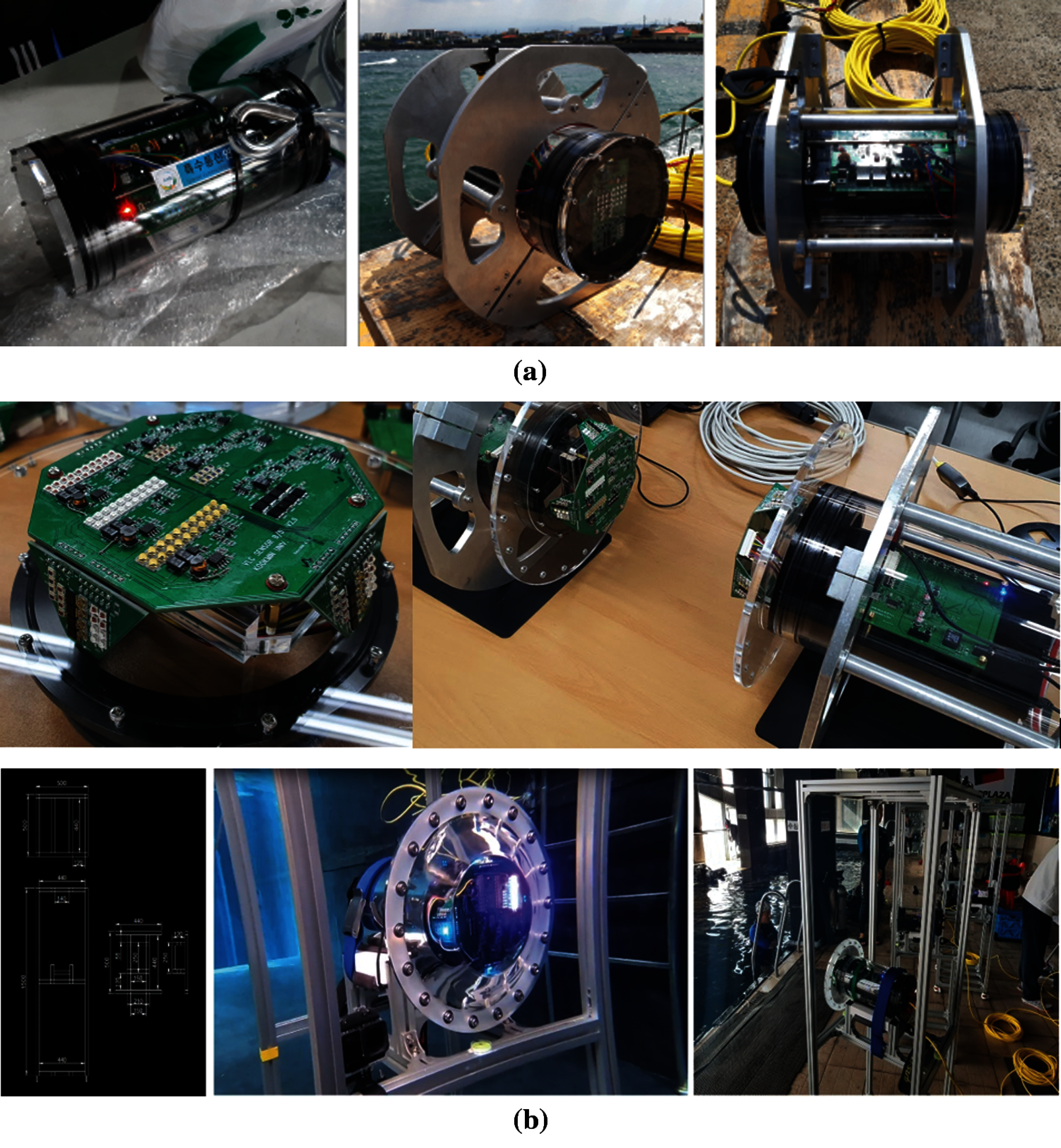
Figure 3: (a): Existing underwater hybrid software-defined modem [29] (b): Hardware modules developed using AFE bundles in UHSDM
The development of current UHSDM technology using analog front-end (AFE) bundles is shown in Tab. 1. To overcome the limitation of the Field of View (FoV), the unit expressing the straightness of the optical spectrum of the current prototype AFE are altered, that is, the transmission/reception angle, spacing, and slope of the receiving (Tx) element are applied differently. Fig 4 shows the hardware components used in UHSDM, the system is integrated with two or more mediums with multiple bands which requires numerous computer buses to operate. AFE generates and processes the signals of individual mediums and bands in UHSDM. It has synchronous or asynchronous communication with the central processing unit and high-speed or low-speed communication. The developed UHSDM adopts two types of media such as visible light and infrared light with different wavelengths. By adopting a specific field-programmable gate array (FPGA) with an integrated Application Processor (AP), the interface connector suitable for the AFE specification was implemented in a hardware description language (HDL).
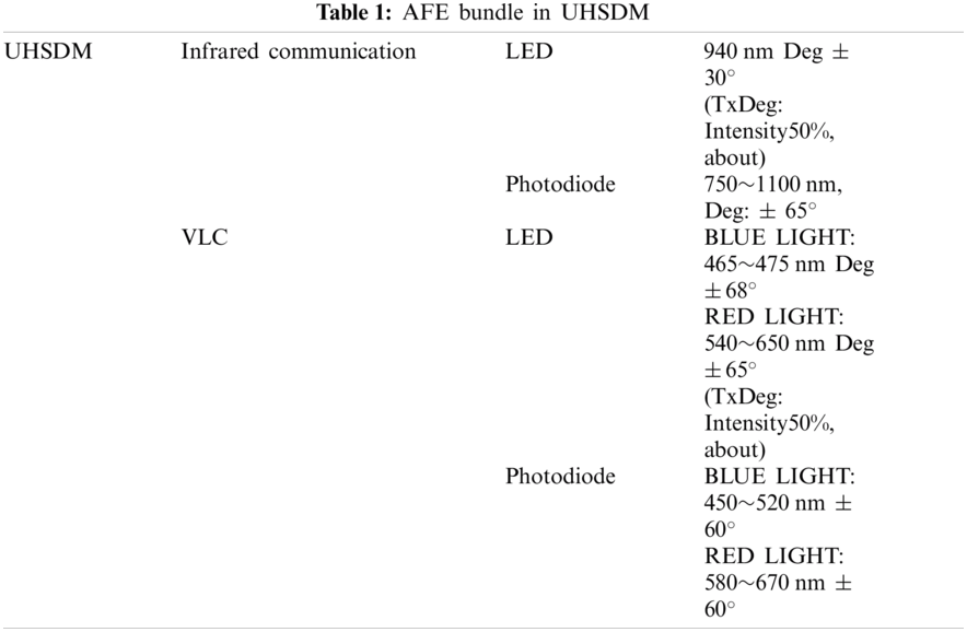
Fig. 5 depicts the protocol suite of UHSDM communication technology. It consists of four major layers such as the physical, data link, data link abstraction, and application layer. The description of each layer is provided below:
• The physical layer and data link layer consist of various underwater media such as acoustic, optical, infrared, and radiofrequency. Each medium is separately built-in UHSDM physical layer due to the different characteristics and limitations of IoUT environment.
• The data abstraction layer consists of different functionalities such as topology management, lightweight addressing, localization management, routing management, network coding, etc. These are used for managing the communication process for transferring (TX) and receiving (RX) the data in UHSDM.
• The network and transport layer is not mandatory in UHSDM communication technology.
• The application layer is responsible for handling the handover mechanism and medium selection mechanism in UHSDM. The major function of the medium selection mechanism is to select the dedicated medium and band during the handover process.
The basic elements and working principles of UHSDM are shown in Fig. 6. The primary component of the UHSDM hardware consists of a transmitter (TX) which consists of sub-modules such as controller, medium switch controller (MSC), modulator, power controller, timestamp, etc. The MSC controls the switch in the UHSDM modem to select the best communication medium such as visible light, acoustic, or infrared. Then, the modulator includes the required data in the format of light or acoustic signals. The acoustic Tx is used to transmit the ultrasonic signal and the VLC Tx or IR Tx is used to transmit light-based signal for the communication between the devices via the underwater channel. The receiver (RX) is used to receive the signal from the transmitter (TX) in the acoustic or light format, then demodulates it to get the original data.
2.4 Channel Selection Mechanism
In this section, the proposed Channel selection algorithm for UHSM is described and is shown in Algorithm 1.
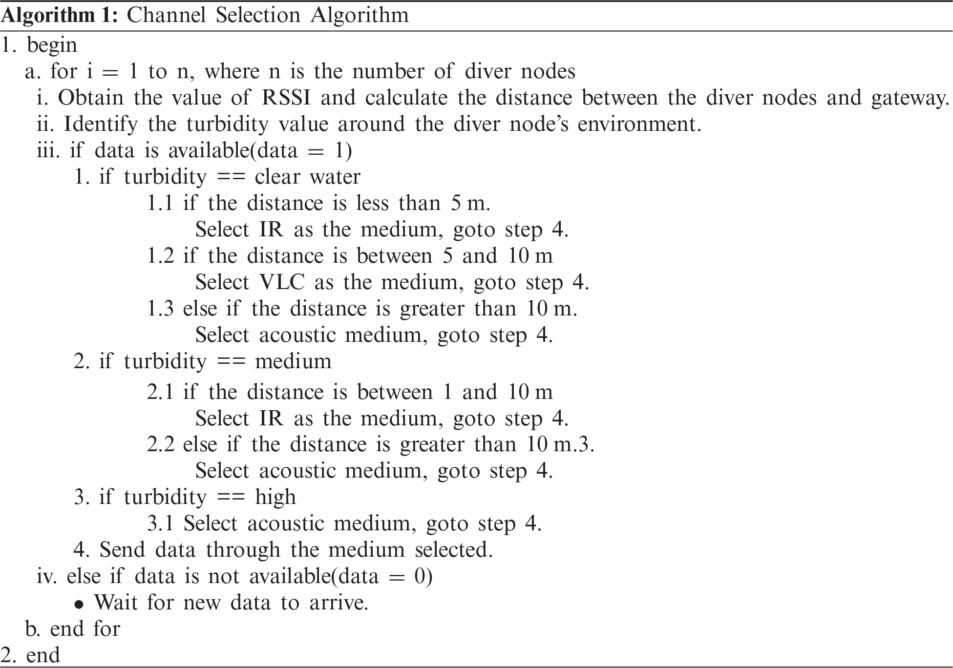
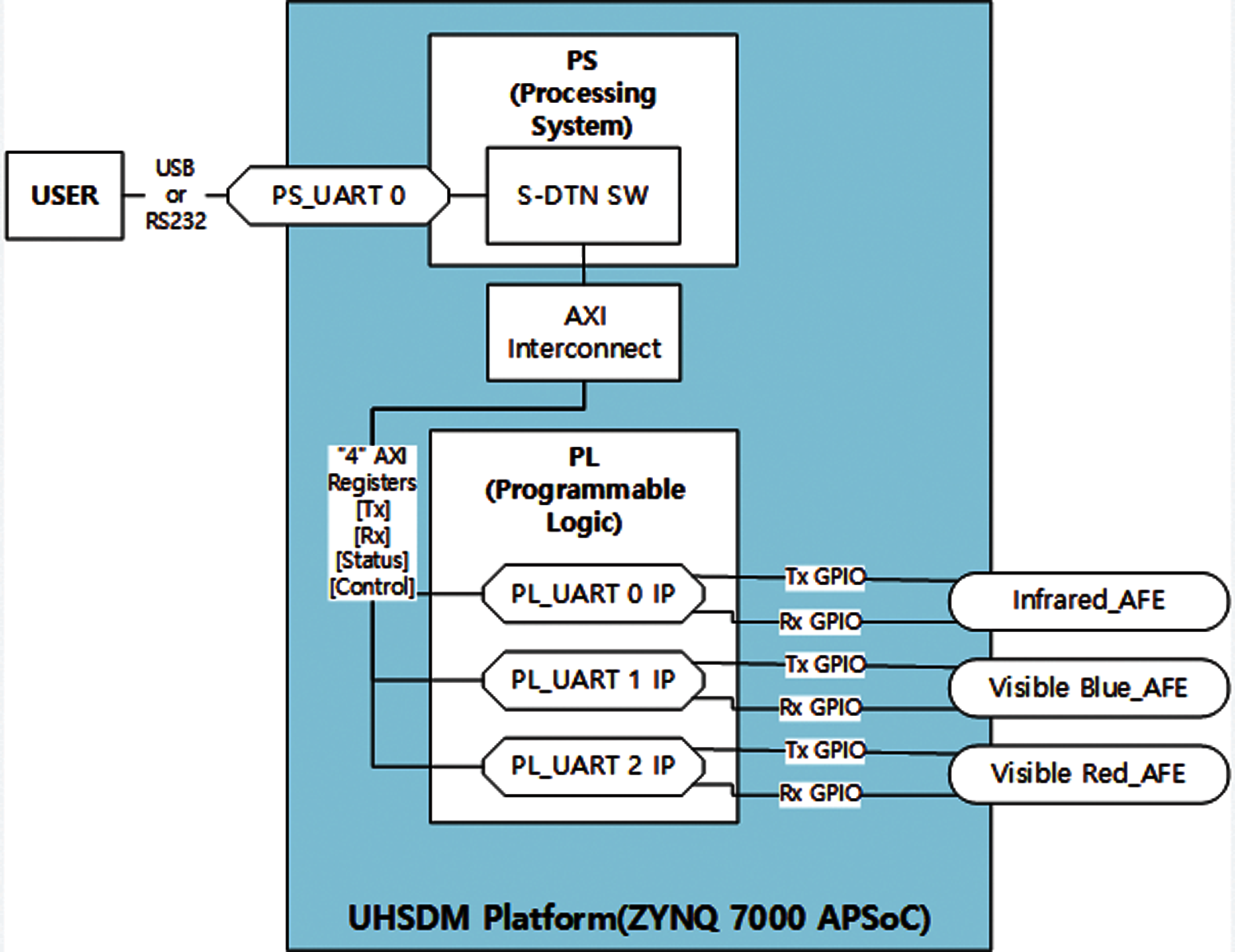
Figure 4: Hardware components of UHSDM
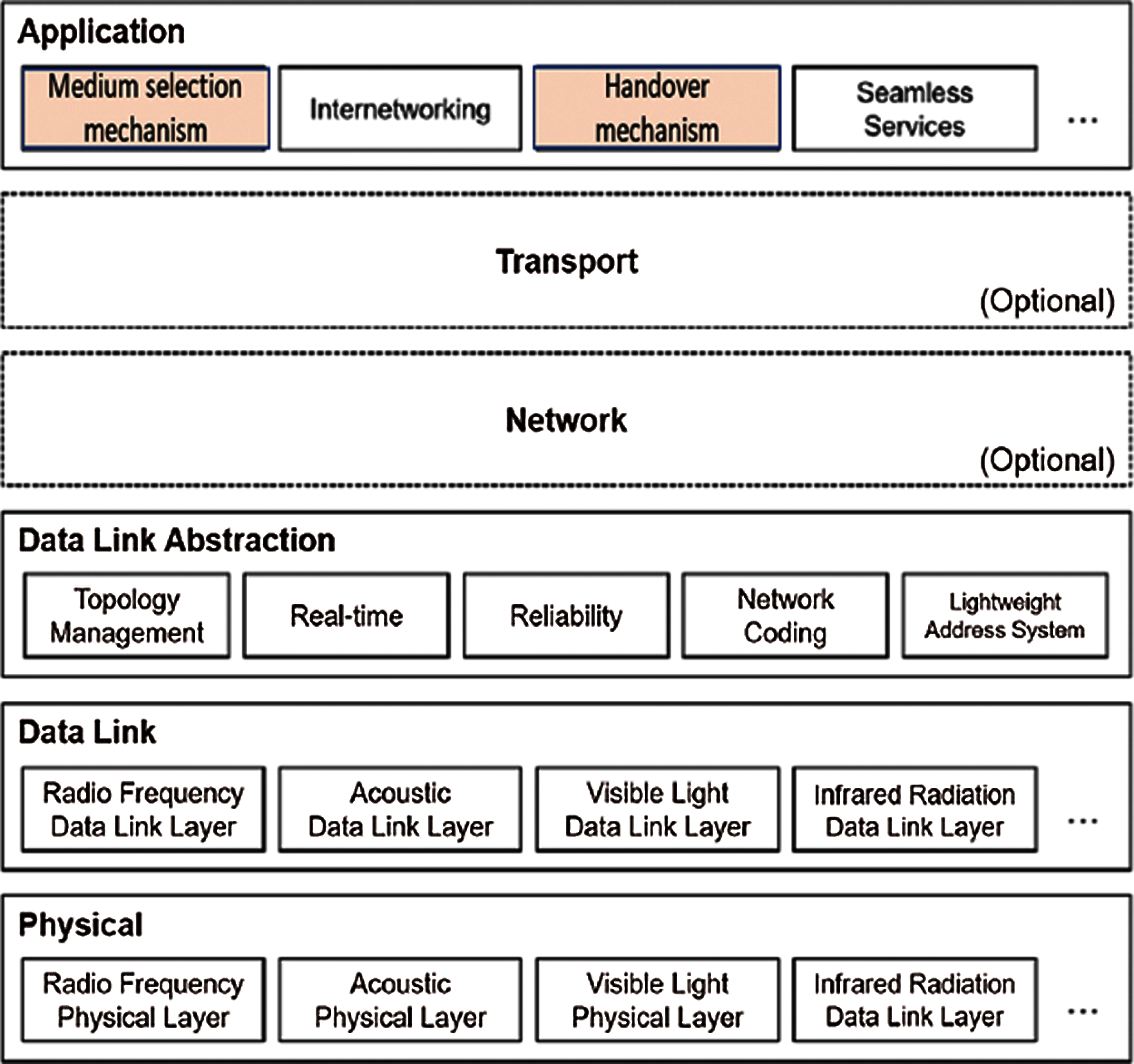
Figure 5: Protocol suite of UHSDM
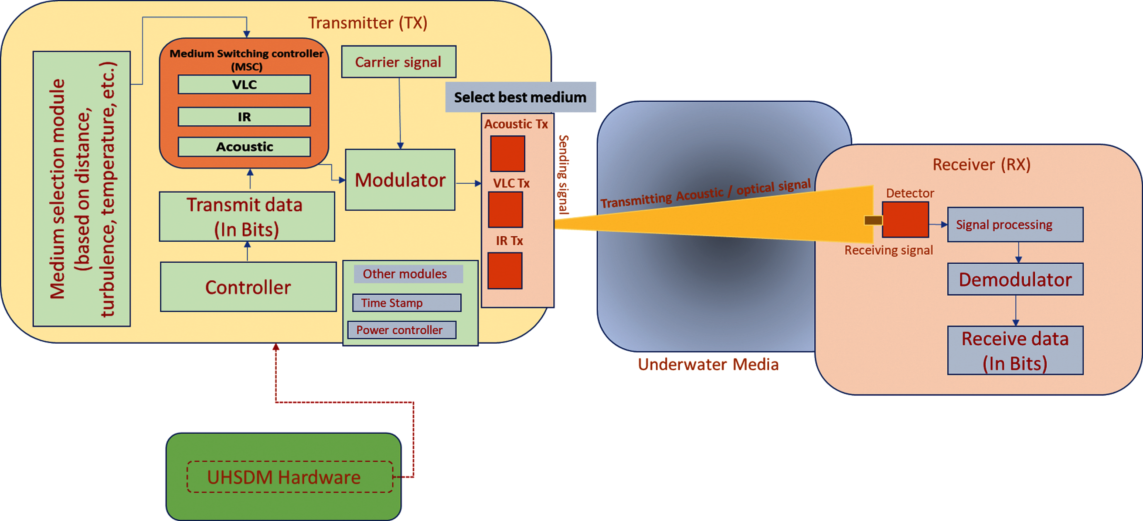
Figure 6: The working process of UHSDM
3 Proposed Handover Mechanism in ADN
This section provides an architecture design for the handover mechanism in ADN along with the algorithm, working principle, and sequence diagram.
3.1 Architectural Design for Handover Mechanism in ADN
Fig. 7a shows the general architecture of the handover mechanism in ADN. The ADN is composed of various components as described below:
• UHSDM based gateway (UGW) is the base station (BS) of ADN which acts as the AD-VLR in the ADN system.
• AD-HLR: Advanced diver networks home location register (AD-HLR) is a server found in the Terrestrial Networks (TN), it contains all the information about all the divers and networks ‘parameters. It acts as the permanent database in ADN.
• AD-VLR: Advanced diver networks visitor location register (AD-VLR) acts as the temporary database in ADN. Its major role is to manage mobility in ADN.
• Diver: The ADN consists of various divers and each diver is connected with smart IoT devices for the communication between UGW and divers.
• Cells: can host one or a bunch of divers that are strongly interconnected.
• UGW sub-modules: The UGW is the base station of ADN which consists of sub-modules such as channel selection mechanism (CSM) and mobility management engine (MME).
• Channel selection mechanism: CSM is the sub-module installed in UGW, which is used to choose the best medium for communication between UGW and divers in ADN using the wireless communication medium such as acoustic, VLC, IR, etc.
• Mobility management engine: MME is the sub-module installed in UGW, which consists of AD-VLR that can hold the mobile location history of divers. Also, the MME will update and store the location of divers continuously during the handover process, and pass that information to AD-HLR in terrestrial area network.
• D2D: This shows the diver-to-diver connection inside the cell in ADN.
• Transition area: It is a handover margin where the diver handover its connection from UGW1 to UGW2.
• Emergency notification: Once the diver in ADN face difficulties, it uses the best medium for communication between the gateway and diver. Also, it supports strong interconnection between diver-to-diver in emergency cases.
• Trigger handover: handover is triggered when the received signal power for the connected UGW is almost equal to the threshold value.
• Handover position: H1 and H2 are the handover positions of divers ADN.
Fig. 7b shows the conceptual architecture of the handover mechanism from cell A to cell B in ADN. The conceptual architecture consists of cell A and cell B connected to UGW-1 and UGW-2, respectively. In the beginning, diver Y in cell A is connected to the UGW-1 using wireless communication such as acoustic, optical, and IR. Once the diver Y reaches the transition area of cell B, the handover process begins, and the UGW-2 uses the best medium to connect the diver Y. After the connection establishment is made by the diver to UGW2, the UGW-1 release the connection of diver Y.
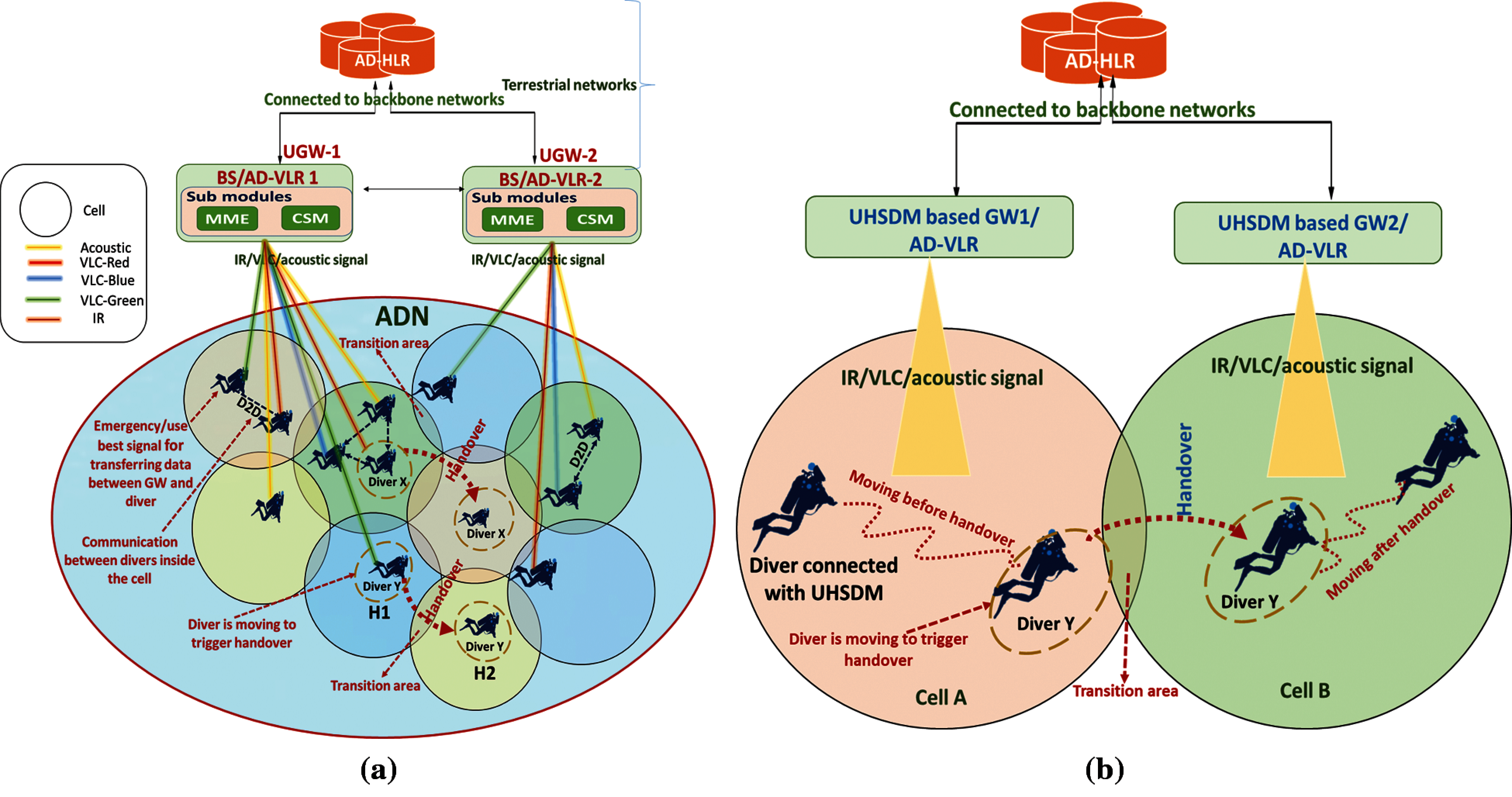
Figure 7: (a) General architecture and components of ADN. (b) Handover conceptual architecture from cell A to cell B in AND
Fig. 8 represents the proposed scenario of the handover mechanism in ADN. This ADN architecture consists of terrestrial networks and underwater networks (1) The terrestrial networks consist of AD-HLR, which is used to store and update all the information regarding UGW-1, UGW-2, and UGW-3 in ADN. (2) The underwater networks consist of cell A, cell B, and cell C that are connected to UGW-1, UGW-2, and UGW-3 respectively using wireless communication mediums such as acoustic, optical, and IR. Each cell in ADN has a diver or number of divers. The divers inside the cell can be communicated using a D2D connection.
In the proposed scenario, diver 1.4 in cell A moves the position from H1 to H2 of cell B and from H2 to H3 of cell C. Handover triggering process and working process is shown in the steps given below:
• Step1: Initially, the diver 1.4 in position H1 is connected to AD-VLR-1.
• Step 2: Diver 1.4 in position H1 is now moving from cell A to cell B via transition area.
• Step 3: Once diver 1.4 reaches the transition area of cell B. Diver 1.4 triggers handover.
• Step 4: AD-VLR-2 will make the connection to diver 1.4 using the best medium by selection mechanism (acoustic/optical/IR) and now diver 1.4 is in position H2.
• Step 5: After the connection establishment is made by the diver 1.4 to AD-VLR-2, the AD-VLR-2 will send the message to AD-VLR-1 to release the connection of diver 1.4.
• Step 6: AD-VLR-1 will release the connection of diver 1.4 after receiving the message from AD-VLR-2.
• Step 7: Finally, AD-VLR-1 and AD-VLR-2 will update the position information of diver 1.4 to AD-HLR.
• Step 8: Same procedure is followed for the handover process from position H2 to H3 in the proposed ADN scenario.
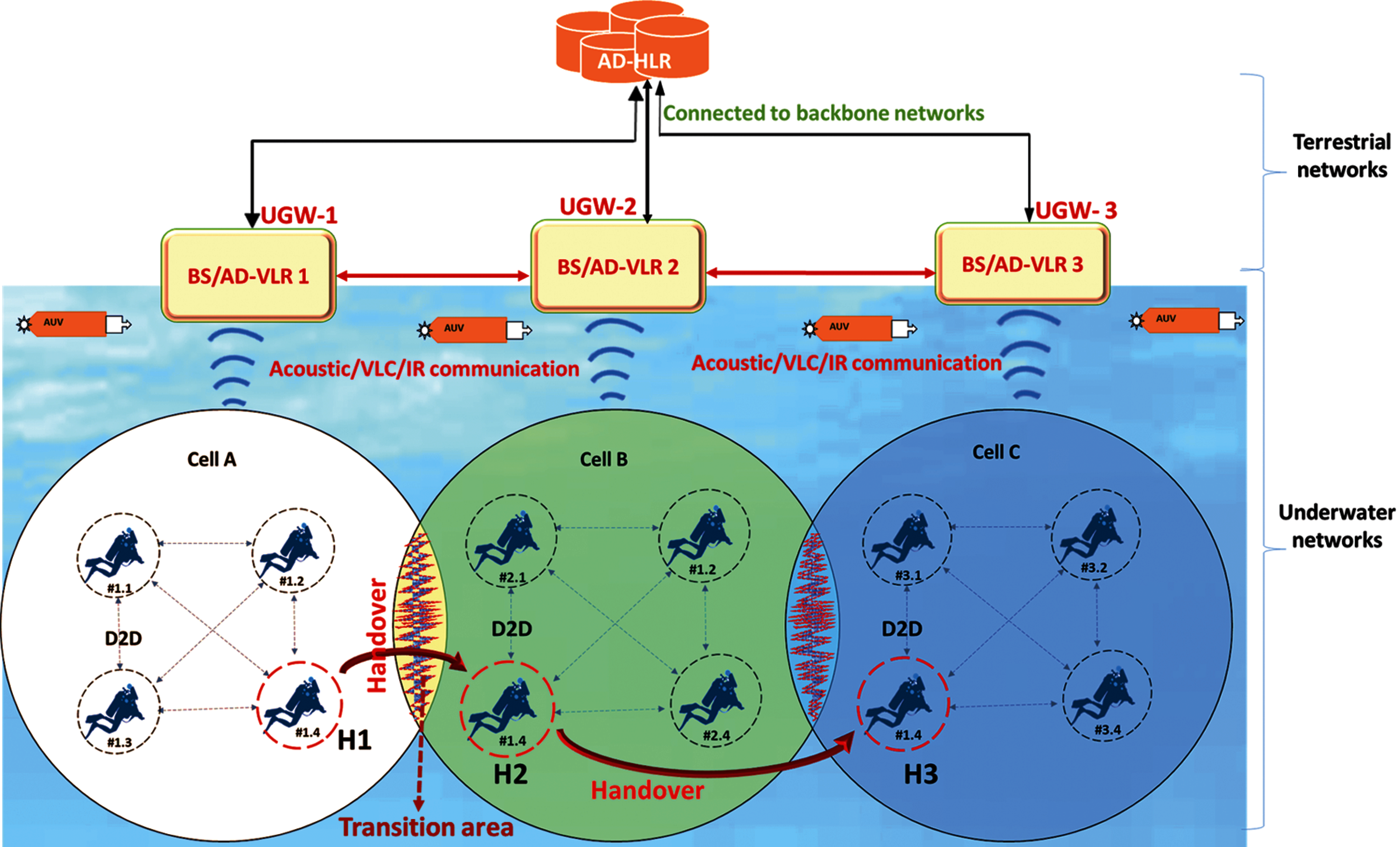
Figure 8: Proposed scenario of handover mechanism in ADN
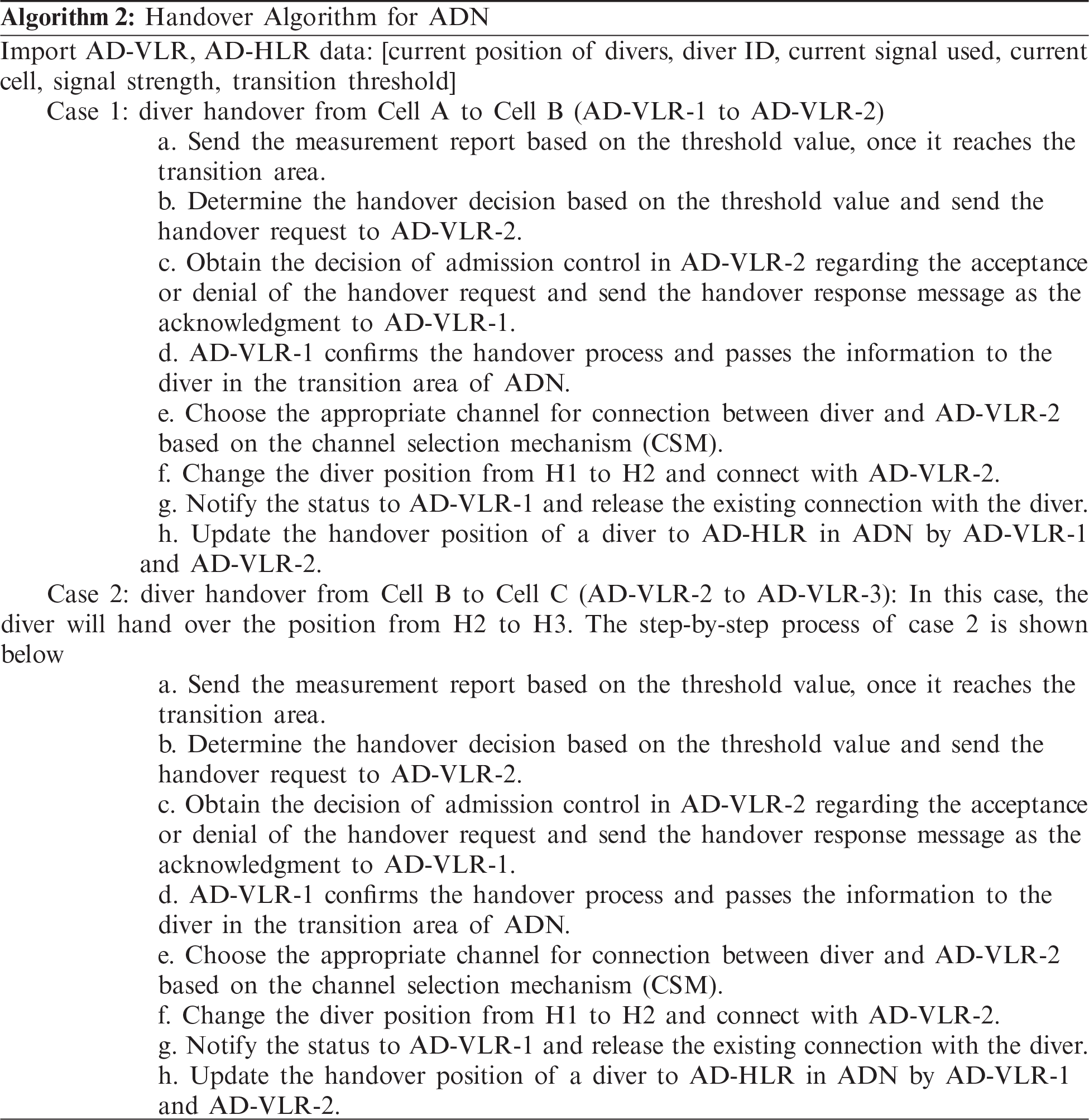
3.3 Sequence Diagram and Handover Algorithm in ADN
The handover message sequence diagram of ADN is shown in Fig. 9. The sequence diagram shows the handover process of diver from AD-VLR-1 to AD-VLR-2 and from AD-VLR2 to AD-VLR-3. In this case, the diver will change the position from H1 to H2 and from H2 to H3 in ADN. The handover mechanism in ADN is shown in Algorithm 2.
4 Experimental Setup and Results
In this section, the implementation of the handover mechanism using UHSDM is described, and the test results are analyzed.
4.1 Testbed Setup and Deployment
Fig. 10 shows the deployment of UHSDM in the underwater environment with an experimental setup. It consists of different types of equipment such as diver, UGWs or transmitter/receiver (TX/RX), and transmission medium. The transmission medium such as VL blue and VL red is used for transmitting the data. The diver is connected with the UHSDM device. The transmitter end shows the transmission of data in UHSDM and the receiver end shows the receiving of data in UHSDM.
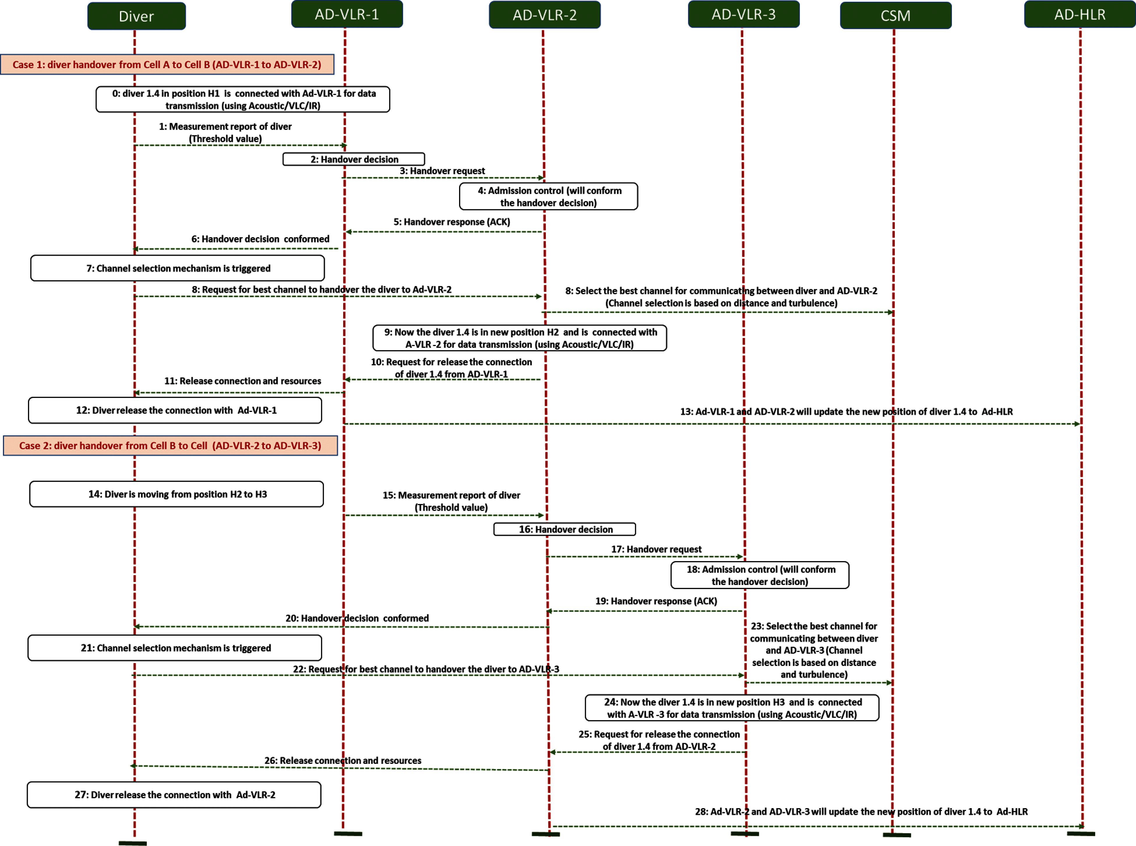
Figure 9: Sequence diagram of diver handover from AD-VLR-1 to AD-VLR-2 and from AD-VLR-2 to AD-VLR-3 AND
The environmental setup of UHSDM based handover mechanism is shown in Fig. 11. The installation and deployment process were performed in the test tank of 8 m length and 3.6 m width. It consists of two fixed UGWs and one mobile ADN device carried by the diver participating in the test that were placed at the same depth of 0.6 m. The distance (d1) between the two fixed UGW's devices was set to 1.5 m and the distance (d2) of mobile ADN devices with fixed mobility and UGW's was set to 1.0/1.5 m.
Fig. 11 shows the environmental setup of the handover testbed in the pool environment attached with the components such as UGW-1, UGW-2, AD-VLR 1, AD-VLR 2, and AD-HLR.
The test for UHSDM based handover mechanism was performed based on Fig. 12. The test for UHSDM based handover mechanism was performed based on the following conditions:
• The test terminal program timestamps the log of transmitted and received packets.
• The mobile ADN device transmits packets (20 bytes) of the same length at intervals of 500 m/s.
• The moving speed (S) m/s of the mobile ADN device moves from the starting point to the endpoint at the measuring distance of 8 m and at the average speed of 0.2 m/s which is similar to the actual diver activity scenario. At the same time, the time taken to reach the point from 0 m to 8 m is also recorded.
• The monitoring terminal records the time when UGW device #1 started receiving the signal transmitted by the mobile ADN device and the time when the reception was terminated (departure time). At this time, if CRC occurs, it is also recorded.
• The monitoring terminal records the time when the UGW #2 device started receiving the signal transmitted by the mobile ADN device and the time when the reception was terminated (departure time). At this time, if CRC occurs, it is also recorded.
• After finishing the recording, the diver moving speed is calculated.
• Find the shaded section in which no reception record has occurred in both UGW devices #1 and #2.
• Finally, find the distance of the shaded section.
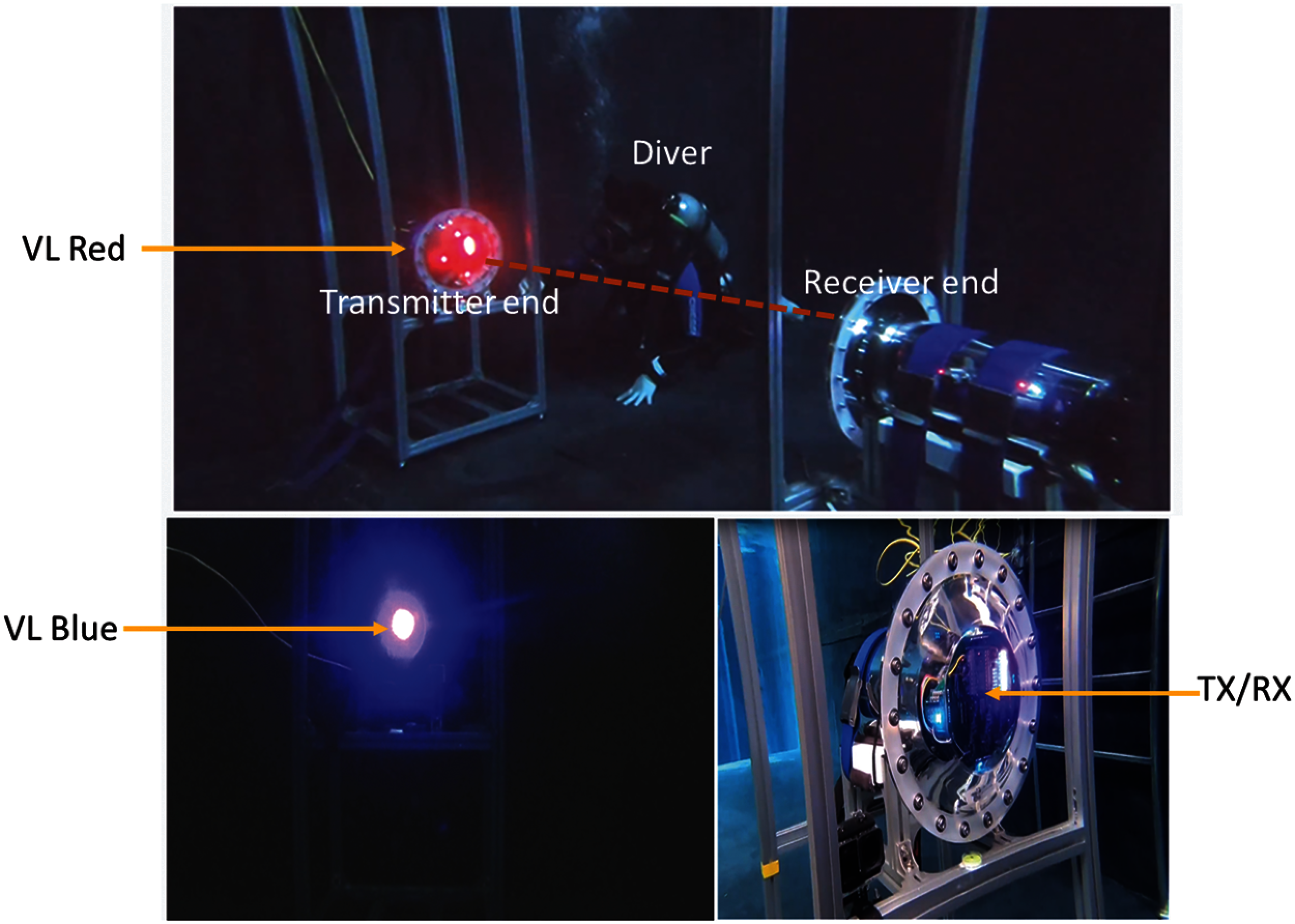
Figure 10: UHSDM device installation in the underwater environment
4.2 Handover Tests and Results
The handover mechanism in ADN is described in Section 3. The packets exchanged during handover from UGW-1 to UGW-2 are shown in Fig. 13 and the signal is stable in the physical layer, hence the packet handover is guaranteed. The signal handover method at the physical layer is also referred to as “hard handover”. Here, we have implemented and tested the hard handover using VLC and IR, which are individual media constituting the AFE bundle of the UHSDM system under development.
• As shown in Fig. 12, three UHSDM prototypes were deployed as terminals attached to the gateway and the diver. Two gateways are fixed at intervals of l meter (maximum 5 m) and the diver moves at a speed of m/s (average 0.2 m/s) while maintaining distance (maximum 2 m) from the gateways and tells the gateway to send a packet.
• Measure the diver's total travel distance and travel time, the entry and exit points of the gateway to derive the diver's movement speed, and the distance between the communication overlapping area and the shaded area between the two gateways.
• When the distance between the two gateways is 1.5 m and the distance between the diver and the gateway is 1.0 m, the handover is successful because the shaded area of the blue visible light communication does not occur in both the 1st and 2nd UHSDM prototypes.
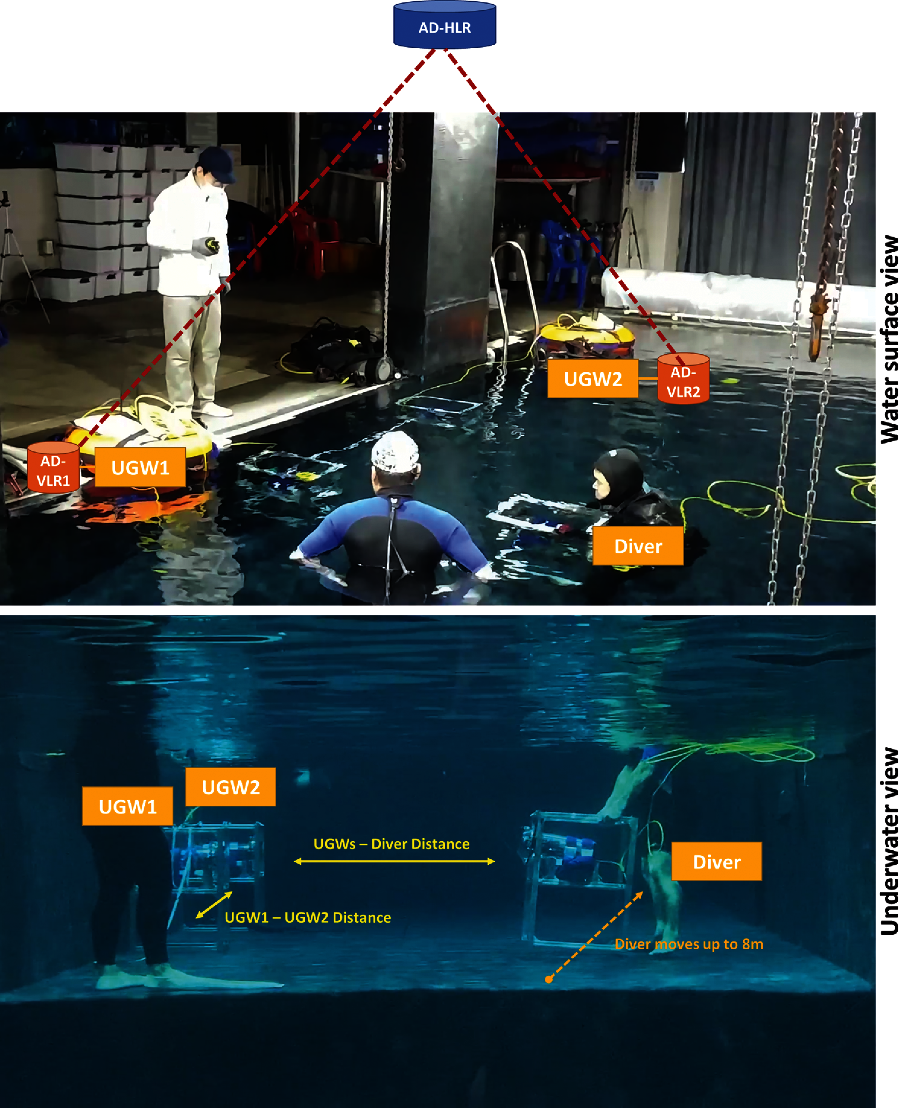
Figure 11: Handover testbed environmental setup
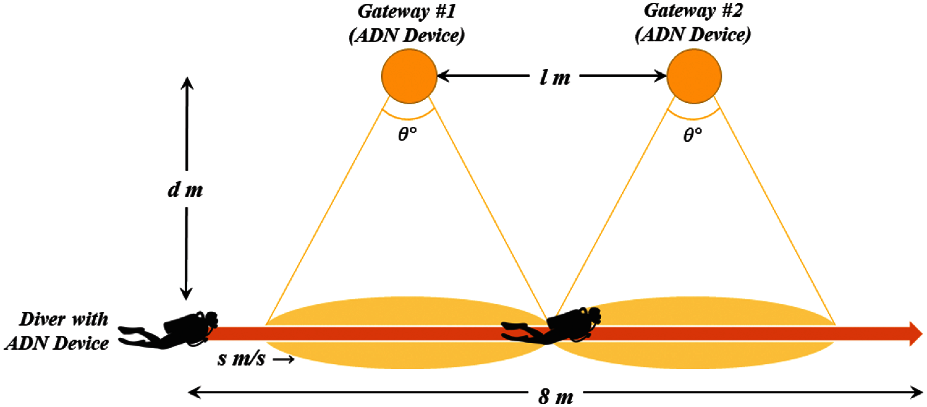
Figure 12: Handover testbed sketch
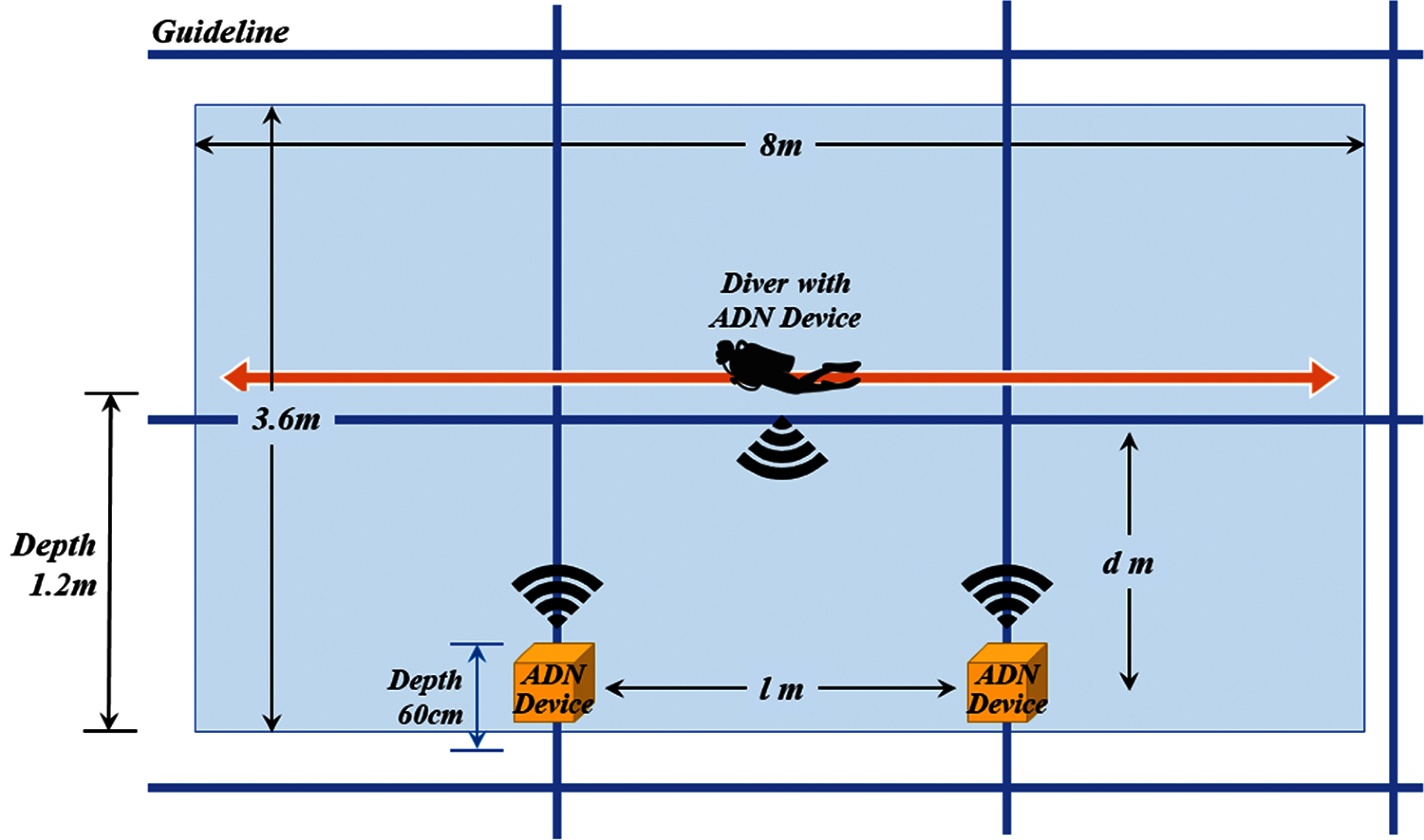
Figure 13: Handover experimental outline
Tab. 2 and Tab. 3 shows the result of the hard handover test performed in water and air respectively. When handover occurs, overlapping occurs in the test results, and the shaded section is indicated as ‘minus’ in the table. The description of the categories is included in the table. Also, Fig. 14 shows the handover successful rate during trial 1, trial 2, and trial 3 between the transmitter (TX) and receiver (RX).
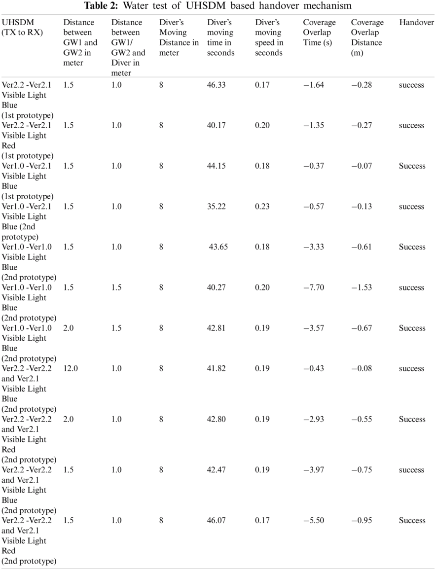
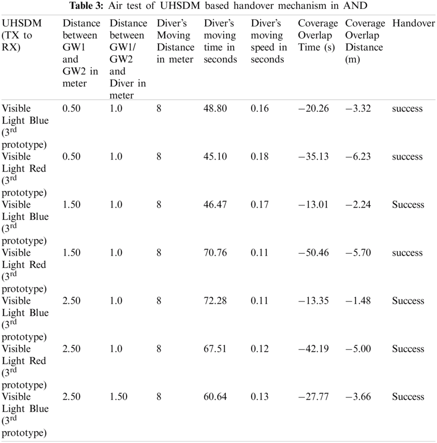
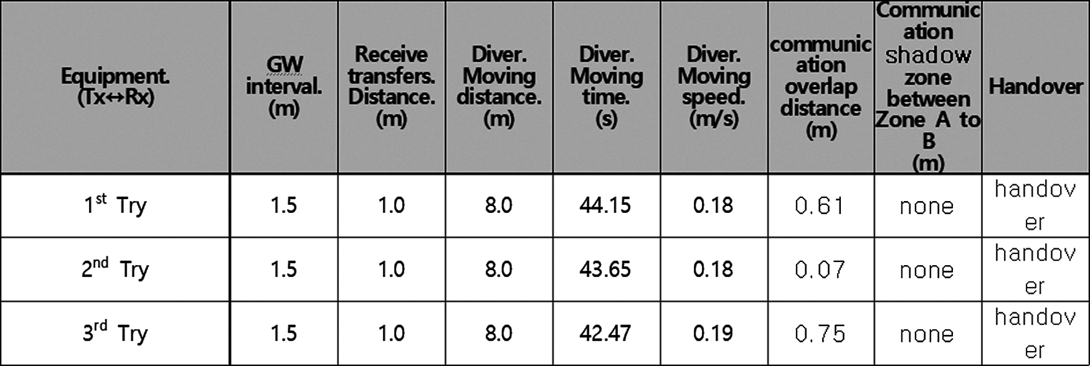
Figure 14: A handover success rate of using UHSDM
IoUT applications play a significant role in the industry, military, and scientific community for deep-sea exploration, oceanography, surveillance, etc. Advanced diver network is one of the IoUT applications that face difficulty in monitoring diver networks environment due to the various limitations of IoUT environment such as low bandwidth, low data rate, connectivity issues/link failure, attenuation, device memory storage limitation, low battery life, etc. For performing reliable data transfer and to select the best medium among acoustic, VLC, and RF in underwater diver networks, the UHSDM prototype was developed. However, in ADN, the frequency of mobility is high. This causes a delay in data transmission, re-routing errors, link failures, etc. In case of emergency, the diver's life may be at risk.
In order to deal with mobility, connectivity issues, energy-efficiency communication, and reducing the latency of data transfer in ADN, a handover mechanism based on pre-built UHSDM was proposed in this paper. This paper focused on developing the new prototype design of UHSDM, which utilizes a fast and energy-efficient handover scheme to support the divers during an emergency. Also, the CSM is utilized in UHSDM to select the best channel among acoustic, VLC, IR, etc. Additionally, this paper shows the comparison result of UHSDM based handover experiment in the terrestrial environment and underwater environment by adding the real field experimental results of air tests and underwater tests with various distances. As future work, the UHSDM based handover techniques can be applied for various IoUT applications. Also, the UHSDM technology can consider other mediums such as visible light green, magnetic induction, etc. to improve the reliable data transmission in the IoUT applications.
Acknowledgement: The authors sincerely acknowledge the support from Seung-Geun Kim of Ocean Engineering System Research Division, Korea Research Institute of Ships and Ocean Engineering, Korea, for this research. Also, the authors would like to thank the anonymous reviewers for their valuable comments.
Funding Statement: This research was a part of the project titled “Development of the wide-area underwater mobile communication systems” funded by the Ministry of Oceans and Fisheries, Korea.
Conflicts of Interest: The authors declare that they have no conflicts of interest to report regarding the present study.
1. NOAA, America's Coastal & Ocean Agency, “How much water is in the ocean?”, 2021. [Online]. Available: https://oceanservice.noaa.gov/facts/oceanwater.html, 2017. [Google Scholar]
2. M. F. Ali, D. N. K. Jayakody, Y. A. Chursin, S. Affes and S. Dmitry, “Recent advances and future directions on underwater wireless communications,” in Arch Computat Methods Eng 27, Springer, Barcelona, Spain, vol. 27, pp. 1379–1412, 2020. [Google Scholar]
3. L. Liu, S. Zhou and J. H. Cui, “Prospects and problems of wireless communication for underwater sensor networks,” Wirel. Commun. Mob. Comput, vol 8, pp. 977–994, 2008. [Google Scholar]
4. N. Saeed, A. Celik, T. Y. Al-Naffouri and M. S. Alouini, “Underwater optical wireless communications, networking, and localization: A survey,” Ad Hoc Networks, vol. 94, pp. 101935, 2019. [Google Scholar]
5. K. M. Gul, C. Kaya, A. Bektas and Z. Bingul, “Design and control of an unmanned underwater vehicle,” in 4th Int. Symp. on Multidisciplinary Studies and Innovative Technologies (ISMSITIstanbul, Turkey, pp. 1–9, 2020. [Google Scholar]
6. M. Bernardi, C. Cardia, P. Gjanci, A. Monterubbiano, C. Petrioli et al., “The diver system: Multimedia communication and localization using underwater acoustic networks,” in 20th IEEE Int. Symp. on a World of Wireless, Mobile and Multimedia Networks (WoWMoMWashington, DC, US, pp. 1–8, 2019. [Google Scholar]
7. P. Kumar, P. Kumar, P. Priyadarshini and Srija, “Underwater acoustic sensor network for early warning generation,” 2012 Oceans, Hampton Roads, VA, USA, pp. 1–6, 2012. [Google Scholar]
8. W. Zhang, T. Zhou, D. Peng and J. Shen, “Underwater pipeline leakage detection via multibeam sonar imagery,” Journal of the Acoustical Society of America, vol. 141, pp. 3917–3917, 2017. [Google Scholar]
9. T. A. Mellin and O. Ravik, “Autonomous underwater system for pipeline leak detection and inspection,” in Proc. of the 6th Int. Symp. on Unmanned Untethered Submersible Technology, Durham, NH, USA, pp. 15–24, 1989. [Google Scholar]
10. H. Song, J. Song and P. Ren, “Underwater pipeline oil spill detection based on structure of root and branch cells,” Journal of Marine Science and Engineering, vol. 8, no. 12, pp. 1–12, 2020. [Google Scholar]
11. C. R. Chase, S. Van Bibber and T. P. Muniz, “Development of a non contact oil spill detection system,” in Proc. of OCEANS 2005 MTS/IEEE, Washington, DC, USA, vol. 2005, pp. 1352–1357, 2005. [Google Scholar]
12. C. M. G. Gussen, P. S. R. Diniz, M. L. R. Campos, W. A. Martins, F. M. Costa et al., “A survey of underwater wireless communication technologies,” Journal of Communication and Information Systems, vol. 31, no. 1, pp. 242–255, 2016. [Google Scholar]
13. X. Chen, M. J. Kim, S. H. Yoo, N. Y. Park and H. Y. Youn, “Efficient and prompt handover in LTE-based systems by predicting the target eNodeBs,” in Proc. - 2014 Int. Conf. on Cyber-Enabled Distributed Computing and Knowledge Discovery, Shanghai, China, pp. 406–413, 2014. [Google Scholar]
14. J. Agrawal, R. Patel, P. Mor, P. Dubey and J. M. Keller, “Introduction to the basic LTE handover procedures,” in 2015 Int. Conf. on Communication Networks (ICCNGwalior, India, pp. 197–201, 2015. [Google Scholar]
15. G. Tomasov, M. Wu, J. Wen and H. Liu, “LTE Fixed-point handover algorithm for high-speed railway scenario,” in Proc. of 2013 3rd Int. Conf. on Computer Science and Network Technology (ICCSNTDalian, China, pp. 919–923, 2014. [Google Scholar]
16. M. Moradi, J. Rezazadeh and A. S. Ismail, “A reverse localization scheme for underwater acoustic sensor networks,” Sensors, vol. 12, no. 4, pp. 4352–4380, 2012. [Google Scholar]
17. G. T. Reddy, M. P. K. Reddy, K. Lakshmanna, R. Kaluri, D. S. Rajput et al., “Analysis of dimensionality reduction techniques on big data,” IEEE Access, vol. 8, pp. 54776–54788, 2020. [Google Scholar]
18. P. K. R. Maddikunta, T. R. Gadekallu, R. Kaluri, G. Srivastava, R. M. Parizi et al., “Green communication in IoT networks using a hybrid optimization algorithm,” Computer Communications, vol. 159, pp. 97–107, 2020. [Google Scholar]
19. R. Kaluri, D. S. Rajput, Q. Xin, K. Lakshmanna, S. Bhattacharya et al., “Roughsets-based approach for predicting battery life in IoT,” Intelligent Automation and Soft Computing, vol. 27, no. 2, pp. 453–469, 2021. [Google Scholar]
20. K. F. Haque, K. H. Kabir and A. Abdelgawad, “Advancement of routing protocols and applications of underwater wireless sensor network (UWSN)---A survey,” Journal of Sensor and Actuator Networks, vol. 9, no. 2, pp. 1–31, 2020. [Google Scholar]
21. R. Z. Ahamad, A. R. Javed, S. Mehmood, M. Z. Khan, A. Noorwali et al., “Interference mitigation in D2D communication underlying cellular networks: Towards green energy,” Computers, Materials and Continua, vol. 68, no. 1, pp. 45–58, 2021. [Google Scholar]
22. A. R. Javed, R. Abid, B. Aslam, H. A. Khalid, M. Z. Khan et al., “Green5 g: Enhancing capacity and coverage in device-to-device communication,” Computers, Materials & Continua, vol. 67, no. 2, pp. 1933–1950, 2021. [Google Scholar]
23. F. Bouabdallah, “Time evolution of underwater sensor networks coverage and connectivity using physically based mobility model,” Wireless Communications and Mobile Computing, vol. 2019, pp. 1–9, 2019. [Google Scholar]
24. A. Yahya, S. ul Islam, A. Akhunzada, G. Ahmed, S. Shamshirband et al., “Towards efficient sink mobility in underwater wireless sensor networks,” Energies, vol. 11, no. 6, pp. 1–12, 2018. [Google Scholar]
25. N. K. Sinai, J. I. Namgung, S. Y. Shin and S. H. Park, “Handover protocol in Ad-hoc diver networks using visual light communication,” in Int. Conf. on Ubiquitous and Future Networks (ICUFNZagreb, Croatia, pp. 604–609, 2019. [Google Scholar]
26. M. V. Jamali, P. Nabavi and J. A. Salehi, “MIMO underwater visible light communications: Comprehensive channel study, performance analysis, and multiple-symbol detection,” IEEE Transactions on Vehicular Technology, vol. 67, no. 9, pp. 8223–8237, 2018. [Google Scholar]
27. G. M. Goodfellow, J. A. Neasham, I. Rendulic, D. Nad and N. Miskovic, “Divernet---A network of inertial sensors for real time diver visualization,” in 2015 IEEE Sensors Applications Symposium (SASZadar, Croatia, pp. 7–12, 2015. [Google Scholar]
28. H. Mo, A. C. Mingir, H. Alhumyani, Y. Albayram and J. H. Cui, “UW-Harq: An underwater hybrid ARQ scheme: Design, implementation and initial test,” in 2012 Oceans, Hampton Roads, VA, USA, pp. 1–5, 2012. [Google Scholar]
29. J. Lee, S. Balkashina, S. H. Yum, J. I. Namgung, S. Y. Shin et al., “Channel selection algorithm based on machine learning for multi-medium/multi-bandwidth communication in underwater internet of things,” in Global Oceans 2020, Singapore – U.S. Gulf Coast, Biloxi, MS, USA, pp. 1–5, 2020. [Google Scholar]
30. K. M. D. Raj, S. H. Yum, K. Eunbi, S. Y. Shin, J. L. Namgung et al., “Multi-media and multi-band based adaptation layer techniques for underwater sensor networks,” Applied Sciences (Switzerland), vol. 9, no. 15, pp. 3187, 2019. [Google Scholar]
 | This work is licensed under a Creative Commons Attribution 4.0 International License, which permits unrestricted use, distribution, and reproduction in any medium, provided the original work is properly cited. |