DOI:10.32604/cmc.2022.020716
| Computers, Materials & Continua DOI:10.32604/cmc.2022.020716 | |
| Article |
An Efficient AES 32-Bit Architecture Resistant to Fault Attacks
1Department of Computer Engineering, College of Computer Engineering and Sciences, Prince Sattam bin Abdulaziz University, Al-Kharj, 11942, Saudi Arabia
2Higher Institute of Applied Sciences and Technology of Sousse, University of Sousse, Tunisia
3Electronics and Micro-Electronics Laboratory, Faculty of Sciences of Monastir, University of Monastir, Tunisia
4METS Research Group, Electrical Engineering Department, National Engineers School of Sfax, University of Sfax, Tunisia
5Higher Institute of Computer Science and Multimedia of Gabes, University of Gabes, Tunisia
*Corresponding Author: Hassen Mestiri. Email: h.mestiri@psau.edu.sa
Received: 04 June 2021; Accepted: 07 July 2021
Abstract: The Advanced Encryption Standard cryptographic algorithm, named AES, is implemented in cryptographic circuits to ensure high security level to any system which required confidentiality and secure information exchange. One of the most effective physical attacks against the hardware implementation of AES is fault attacks which can extract secret data. Until now, a several AES fault detection schemes against fault injection attacks have been proposed. In this paper, so as to ensure a high level of security against fault injection attacks, a new efficient fault detection scheme based on the AES architecture modification has been proposed. For this reason, the AES 32-bit round is divided into two half rounds and input and pipeline registers are implemented between them. The proposed scheme is independent of the procedure the AES is implemented. Thus, it can be implemented to secure the pipeline and iterative architectures. To evaluate the robustness of the proposed fault detection scheme against fault injection attacks, we conduct a transient and permanent fault attacks and then we determine the fault detection capability; it is about 99.88585% and 99.9069% for transient and permanent faults respectively. We have modeled the AES fault detection scheme using VHDL hardware language and through hardware FPGA implementation. The FPGA results demonstrate that our scheme can efficiently protect the AES hardware implementation against fault attacks. It can be simply implemented with low complexity. In addition, the FPGA implementation performances prove the low area overhead and the high efficiency and working frequency for the proposed AES detection scheme.
Keywords: Security; cryptographic circuits; AES; hardware implementation; fault detection; fault attacks
In October 2000, the National Institute of Standards and Technology (NIST) finalizes the Advanced Encryption Standard, when the Rijndael algorithm was adopted as encryption standard [1]. The AES algorithm is used in everyday system to ensure the data confidentiality and the secure of information exchange. Improving the performance of AES circuit is a critical difficulty if the circuit is implemented in the embedded systems. Currently, the AES algorithm is applied in large variety of applications as smart card and mobile communication which require high security level. Therefore, the necessity to increase the AES robustness algorithm against several physical attacks as fault attacks [2–4].
Fault attacks are based on injecting faults into the AES architecture to extract private information [5–8]. The malicious and the natural injected faults decrease the AES robustness in may cause secure data leakage in non-secure implementation. The malicious injected faults are occurred by electromagnetic radiation, voltage/clock glitching and ambient environment. The AES hardware implementation is vulnerable to these errors. It should be noted that the injected errors cause erroneous AES results which make the encrypted message output unreliable. To improve the robustness of the AES implementation, until to date, a few fault detection schemes have been proposed [9–17].
Guo et al. [9] proposed in a new concurrent fault detection approach named re-computing with permuted operands. In this scheme, the AES encryption process is performed on the input message. Then, the input message is permuted and the encryption process is executed again. After re-encryption, the round output is re-permuted and then compared with the original AES round to detected all fault occurred during the encryption process. This proposed scheme in [9] can detect all transient and permanent faults in all AES functions. Yet, it causes more than 58% throughput degradation.
Sheikhpour et al. [10] proposed in an efficient fault-resilient scheme to protect all AES operations. This scheme consists in modifying the basic temporal redundancy where the AES architecture consists of four parts and each part is split into two pipeline stages. This design is independent of the implementation of S-Box function. The authors have shown that their fault-resilient implementation achieves high fault detection rate against the fault attack with low hardware FPGA and ASIC implementation cost.
Sheikhpour et al. [11] proposed a three fault-tolerant architectures which provide different security levels of fault tolerance for AES 128-bit. Those architectures can tolerate all permanent and transient faults. The authors show that their fault detection capability result is close to conventional N-modular hardware and N-tuple temporal redundancy with a low hardware implementation cost.
Mestiri et al. [12] proposed a new AES 128-bit fault detection architecture based on modified time redundancy. In this architecture, the AES round is spilt into two blocks. The first block includes the SubBytes and ShiftRows and the second block consists of MixColumns and AddRoundKey where each block is calculated twice and the round outputs are checked for fault detection. This architecture causes high maximum frequency and can detect 98.45% of transient faults, but it is not capable to detect the permanent faults.
Kamali et al. [13] proposed in an AES pipelining architecture by replicating non pipelined AES blocks. This approach implement a different mechanism compared to loop unrolling and a compact S-Box to reduce memory-based substitution. To protect their new architecture against fault attacks, the authors implement a low cost concurrent fault detection method based on the parity checking where the input parity is compared with the modified AES parity. The fault coverage of this approach achieves 98.7% for the single fault and 53% for the random fault injections.
Benhadjyoussef et al. [14] proposed in a 32-bit AES implementation protected using a hybrid fault countermeasure. This countermeasure presents an efficient method for concurrent checking based on parity testing and time redundancy. The authors illustrate that their proposed scheme can be applicable for the encryption and decryption designs. In addition, the experimental results demonstrate that the proposed countermeasure has high fault coverage.
In this paper, we present a new AES fault detection scheme against fault attacks. We summarize our contributions as:
• The idea is to modify the AES 32-bit architecture. Each AES 32-bit round is split into two half rounds. So the first part of the round is cheeked against error, at the same clock cycle as, the second part of the round is executed and vice versa.
• We have proposed a modified AES 32-bit architecture resulting in new fault detection scheme for securing the nonlinear AES transformations, i.e., SubBytes (Inv_SubBytes), and the linear AES transformations, i.e., ShiftRows (Inv_ShiftRows), MixColumns (Inv_MixColumns) and AddRoundKey in the encryption and the decryption process. The proposed approach is independent of the Inv_S-box and the S-Box are implemented, i.e., composite fields or Look-Up Table implementations. It is important to note that the clock frequency of our scheme is higher, the cost area hardware and the throughput degradation are lower than its counterparts which based on temporal redundancy.
• We prove that the proposed fault detection scheme for the AES 32-bit detects all natural and malicious injected faults. For this purpose, we perform a fault injection attacks against our proposed architecture in all possible AES 32-bit location, i.e., the error comparator detection and the encryption and decryption structure. Through our simulation attacks, after injecting 4.000.000 single, multiple burst, multiple random, stuck-at 0 and stuck-at 1~bit faults, we show that the proposed scheme achieves 89.894%, 99.88585% and 99.9069% fault coverage for transient single-fault, transient multiple-fault and the permanent faults, respectively.
• Finally, we implement the unprotected AES 32-bit and the proposed secured AES architecture on the Xilinx Virtex FPGA platform, and their frequency and area overheads, and throughput and efficiency degradation have been extracted and compared. The FPGA hardware implementation results show that our architecture has lower area overhead, throughput degradation and efficiency degradation, and higher frequency compared with the most recent AES error detection schemes.
The rest of this paper is organized as follows: Section 2 present the background knowledge. In Section 3, we present the hardware implementation results of AES 32-bit. Section 4 presents detailed architecture of the proposed fault detection scheme for the AES. In Section 5, the fault coverages of the proposed detection scheme are compared and discussed. Section 6 presents the hardware implementation results and comparisons. Section 7 concludes the paper.
2.1 Advanced Encryption Standard
The Advanced Encryption Standard is a round-based block cipher which process a data blocks of 128 bits’ lengths 4 × 4 array of bytes called the state, and supports three different cipher keys with lengths of 128, 192 and 256 bits [1]. The AES round number is 10, 12, or 14, when the AES round key length is 128, 192 or 256 bits, respectively. AES expands the initial key into subkeys using the expansion unit. In the AES encryption algorithm, except the initial round and the final round (round 10), the rounds 1–9 consist of 4 transformations, i.e., AddRoundKey, MixColumns, ShiftRows and SubBytes. All the AES transformations are executed on the State matrix (S).
where 0 ≤ i, j ≤ 3, si, j ∈ GF (28).
Block diagram of the AES encryption/decryption is shown in Fig. 1.

Figure 1: The AES encryption/decryption structure
SubBytes (SB): the SubBytes transformation is a non-linear substitution process where each input state byte is substituted by another byte using the S-Box function. This S-Box is computed by the composition of the Affine Transformation (AT) and the Multiplicative Inverse (MI) in the finite field GF(28) as follows:
where the AT is an 8 × 8 matrix:
ShiftRows (SR): In the ShiftRows transformation, each state row is shifting cyclically a certain number of positions where the 2nd, 3th and 4th rows of SSB cyclically shifted by 1, 2 and 3 positions to the left, respectively.
MixColumns (MC): In the MixColumns transformation, each state column of SSR is treating as a 4 terms polynomial in the finite field GF(28) and multiplied x4 + 1 with a fixed polynomial a(x) given by:
The MixColumns transformation can be presented in matrix form as:
AddRoundKey (ARK): The AddRoundKey output state SARK is calculated by Xoring (addition modulo 2) the state input with round keys generated using the key expansion.
In the decryption process, the AES performs the inverse of the corresponding four transformations in the encryption process, i.e., Inv_SubBytes, Inv_ShiftRows, Inv_MixColumns and AddRoundKey.
Fault attacks are an efficient technique to break the unprotected AES hardware implementation. The main idea of this attack is to inject one or several bit faults or byte faults through the AES encryption or decryption execution and then to use the faulty encryption/decryption output to extract the encryption key stored in the cryptographic component. As presented in our previous work [15], we perform a sequences of fault injection at-tacks simulation against the unprotected AES hardware implementation to evaluate its robustness. The experimental results show that those attacks can extract the encryption AES key after injecting certain number of faults which means that fault attacks are powerful against the unprotected AES implementations and it is required to secure the AES hardware implementation against those attacks.
3 AES 32-bit FPGA Implementation
Fig. 2 presents the proposed AES 32-bit architecture to execute the encryption/decryption process. It takes 4 × 32-bit for the plaintext and 4 × 32-bit for the initial key. The AES 32-bit executes the encryption/decryption of the 4 × 32-bit plaintext/ciphertext and the output data is 4~×~32-bit.

Figure 2: AES 32-bit architecture
The proposed AES 32-bit architecture consist of 6 modules:
• Input interface is used to hold 128-bit input plaintext and key encryption as 32-bit words awaiting encryption/decryption process. This interface is controlled using three signals, i.e., plaintext_load, ciphertext_ready and round.
• AES Round encryption/decryption is implemented to execute the encryption/decryption process of plaintext/ciphertext.
• Controller module used to generate the controller signals which ensure AES modules synchronization.
• Key Expander used to generate the AES round keys based on 4 × 32-bit input key.
• Output interface takes 4 × 32-bit plaintext/ciphertext and stores them until executes the total 128-data block.
• AES Library defines all the AES transformations, i.e., AddRoundKey, MixColumns (Inv_MixColumns), ShiftRows (Inv_ShiftRows), SubBytes (Inv_SubBytes).
Fig. 3 presents the details implementation of AES round.

Figure 3: AES round implementation
As seen in Fig. 3, the AES processes each 32-bit data which represents one column of state, via 4 parallel columns.
The proposed 32-bit AES encryption/decryption design has been simulated by ModelSim based on VHDL language and synthesized using Xilinx ISE tools. The target hardware platform selected is the Virtex 5 XC5VFX70T FPGA from Xilinx. The hardware implementation results of the AES 32-bit encryption and decryption are presented in Tab. 1.
As seen in Tab. 1, the occupied area (in slice), the clock frequency (in megaHertz), the throughput (in megabits per second), the efficiency (in megabits per second per slice) for the AES 32-bit encryption and decryption are presented.
The AES 32-bit implementation in encryption process takes 396 slices for 279.38 MHz clock frequency and 2980 Mbps throughput. The AES 32-bit decryption occupies 480 slices for 259.52 MHz clock frequency and 2768.25 Mbps throughput. The hardware performances of AES decryption are less than those of the encryption. This is mainly because of the Inv_MixColumns operation which is more complex than its corresponding in the AES encryption process.

In this section, we first describe the motivations for this work, and then we propose a robust fault detection scheme based on modified temporal redundancy, for the crypto-graphic AES algorithm. We note that although we have considered the AES 32-bit, the fault detection scheme presented in this paper can be applied to other AES sizes (AES-192 and AES-256).
The AES is the main cryptographic algorithm which used for confidentiality information security. This algorithm can be implemented to ensure the information confidentiality as protection against fault attacks. Two reasons can be mentioned for having fault detection scheme for such an important cryptographic algorithm.
• Cryptographic hardware implementations are sensitive to malicious attacks and natural faults such as those based on fault injections; this is the case for the AES algorithm.
• The AES implementation based basic temporal redundancy approach performs the normal encryption and re-encryption using the same round input, where each round necessary 2 clock cycles. The 1st cycle is to make the standard encryption whereas the 2nd is to perform the re-encryption of the same input and to compare the round outputs. The inconvenience of this method is that it increases 100%-time execution and detects only the transient faults.
4.2 Proposed Fault Detection Scheme for the AES
We propose a modified technique of temporal redundancy for the cryptographic AES round to detect all permanent and transient faults, which occur during the process of the encryption algorithm. For this reason, we divided the AES 32-bit column round into two half blocks and a pipeline register has been implemented between them where each half block is performed two times and the encryption outputs are generated in order to detect any injected faults. Given that the pipeline register is implemented in each AES 32-bit column round, the AES critical path is divided into two parts and the maximal frequency is increased. The data processing and the fault detection are simultaneously realized which increases the processing speed of data. Contrary to the basic time redundancy which is to use AES round twice for each input message, the proposed approach is to divide each AES 32-bit column into two half blocks. Then, the first AES 32-bit column part is proved against errors at the same time as the second AES 32-bit column part is processed and vice versa. The proposed fault detection scheme is applied to the AES implementation as shown in Fig. 4.
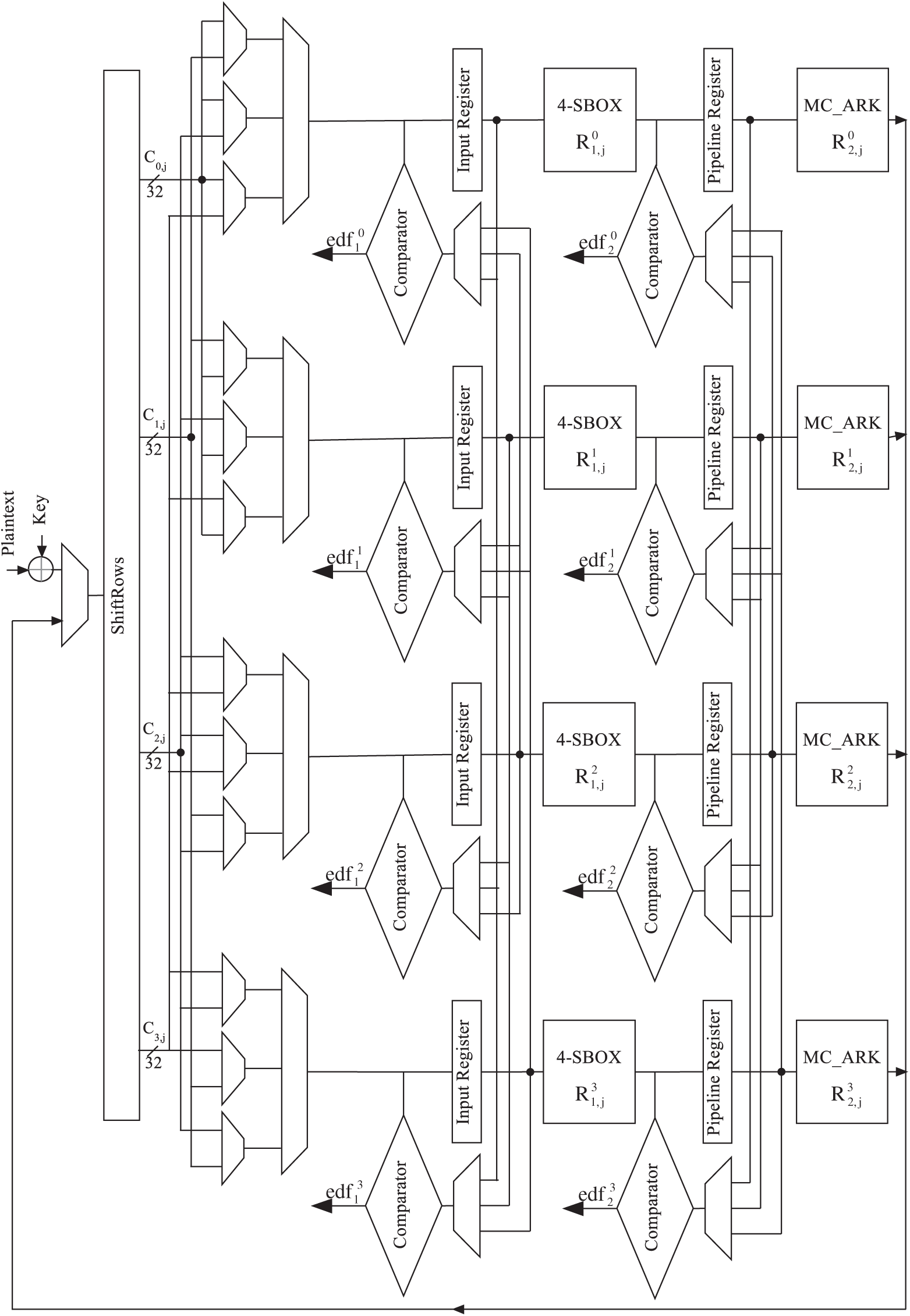
Figure 4: AES 32-bit with fault detection scheme
The AES round is executed 11 times to process the round input. The AES 32-bit column round critical path is split into two parts and pipeline register (PRi) is implemented between them. In Fig. 4, 8 registers are presented. The input registers (IRi) and the pipeline registers (PRi) hold the input and the intermediate values of the 32-bit column computation, while the comparators and the error detection flags
The first half of the AES 32-bit column round

In the 1st clock cycle (k = 1), the initial round is executed where the initial key is XORed with the plaintext and the first ShiftRows transformation is performed. The state message goes through the first half of the first AES 32-bit column round
The IRi and PRi are utilized to stock up the encryption data to be compared with the re-encryption data using the error detection flags. Tab. 2 explicates this procedure:
• The
• The
• The IRi and PRi are loaded in all clock cycles,
• The stored encryption data in IRi and PRi are used in even and odd clock cycles, respectively for errors checking,
• The faults checking of
As seen in Tab. 2 and Fig. 4, the AES 32-bit round operations should switch exchange between the standard encryption process and re-encryption process at each clock cycle. The initial error checking will be performed in the second cycle when the outputs of the first AddRoundKey and ShiftRows 32-bit in the standard encryption process, is compared to their corresponding in the re-encryption execution. The proposed architecture process takes 22 clock cycles to execute the 11 rounds of AES 32-bit.
It should be pointed out although the encryption method is executed at k = 1, the encryption message is not utilized until the k = 2 when the output of
As presented in Fig. 4, the proposed design consists of 8 error detection flags where each error flag ensures the fault detection into two half AES 32-bit columns. Since the proposed architecture consists of four

The proposed design can be also implemented to the AES-256 and AES-192 architectures where the register size is 32-bit ones instead of 256-bit size register and 192-bit size register respectively.
5 Proposed Fault Detection Scheme: Fault Detection Evaluation
To verify the proposed architecture robustness against the fault injection attacks, Simulation series are executed for our AES fault detection scheme using the VHDL language. Three tests of injection fault are considered:
• Single-bit transient faults: this case is occurred when one bit of the encryption/decryption state is modified,
• Multiple-bit transient faults: this case is occurred when at least two bits of the encryption/decryption state are changed,
• Permanent fault: affect the AES hardware architecture and can only be removed through repairing.
Errors are injected in diverse target locations. In detail:
• Error injection into the initial encryption key and plaintext,
• Error injection into all half AES 32-bit columns
• Error injection into the fault detection data path, i.e., the error detection flags and comparators,
• Error injection into all multiplexer, input registers and pipeline registers.
It is noted that the we can inject the same error in the same position two times during one AES round. Also, we have considered all transient and permanent faults for our scheme. In the error checking, the proposed detection scheme utilizes the error detection flags (
We are able to partition the output of the proposed design into four classes:
• Silent fault: the round output is the predicted encryption/decryption data and no error is detected in the encryption/decryption process, which means that the injected faults have no influence on our architecture.
• Undetected error: no injected error is detected even that the round output is erroneous which means that the detection scheme was not capable to detect the occurred or injected faults.
• Detected error: an error is detected and the round output is not the predicted encryption/decryption data which means that the occurred or injected errors were detected using the fault detection scheme.
• False positive: an injected error is detected, however, the round output is the predicted encryption/decryption data.
An efficient AES fault detection scheme should reduce the undetected errors apparition. In addition, it must not authorize the existence the false positives if the round output is the predicted value. The silence false depends mainly on the properties of the design.
Transient single faults: we first analyzed the robustness of the proposed fault detection scheme against single fault attacks. we assume for this fault model a single-bit transient fault is injected into a one of the mentioned location faults. The simulation security is executed using 4,000,000 single-bit faults. Tab. 4 shows our simulation security results for the proposed AES architecture. The percentage of the detected faults is computed as the ratio of the detected faults number to the total of single-bit faults injected into the AES architecture. It can be seen from Tab. 4, the majority part of single-bit transient errors was detected error or classified as false positive. Just a small error percentage was silence fault: about 2.544%. The undetected error percentage achieves 0% against the single-bit transient faults. Therefore, our scheme ensures high AES security level against single fault injection attacks.

Transient multiple faults: The fault detection capability of the multiple-bit transient faults is very significant, since this type is the main error model for the fault injection attacks. In this simulation, we consider the two cases of the multiple-bit transient faults, i.e., burst faults and random faults.
• Burst faults: In this experiment, we analyzed our AES fault detection scheme with respect to faults affecting at last two bits. We inject multiple-bit transient faults affecting any AES state with the number of the erroneous bits ranging from 2 to 7. The errors are injected into the previously mentioned locations. Therefore, using eight error detection flags (
• Random faults: in this experiment, we inject 4,000,000 faults with random faulty bit number in the previously mentioned locations. As seen in Tab. 4, while the proposed AES fault detection scheme is simulated with random-bit transient faults, the percentage of the undetected error is equal to 0.00015% while 99.88585% can be detected. The undetected fault case will be occurred if an attacker injects the same fault in two AES 32-bit columns with respect the same constraints, i.e., the faults are injected in similar locations at the same clock cycle.
Permanent faults: in this experiment, we consider the stuck-at-0 and stuck-at-1 faults where the injected faults remain more than one clock cycle. we inject 4,000,000 faults in all possible location. As mentioned in Tab. 4, the undetected error percentage achieves 0% against the single-bit permanent faults. The majority part of random permanent faults was classified as detected error. Just a very small error percentage was not detected or silence fault or: about 0.0001% and 0.018% respectively. Our attack results show that our architecture ensures high security level against permanent fault attacks.
In order to evaluate the proposed design in terms of hardware implementation costs, we report the encryption/decryption implementation processes for AES 32-bit on FPGA XC5VFX70T from Xilinx Virtex-5 family. Yet, two architectures have been implemented: the unprotected and the protected AES implementations. Those architectures have been modeled using VHDL description language, simulated by ModelSim 10.1 and synthesized with Xilinx ISE 14.1.
The following synthesis results of the proposed unprotected and protected architectures for FPGA implementation are reported in Tabs. 5 and 6:
• Area
• Area overhead
• Working frequency
• Frequency overhead
• Throughput overhead
• Efficiency overhead
For all FPGA implementation results, we compute the cost overhead using Eq. (10):
where the costUn and costPr are the hardware implementation costs of unprotected and protected architectures, respectively.

As seen in Tab. 5, the unprotected AES encryption (decryption) takes 396 (480) slices for 279.38 (259.52) MHz frequency. The protected AES encryption (decryption) occupies 24.24% (26.25%) more slices and the frequency increase by 44.25% (39.31%) than the unprotected AES. Since the critical path of the proposed AES architecture is split into two parts, the working frequency is increased. As it can be seen in the Tab. 5, the frequency speed-up to 44.25% in encryption process compared to the unprotected AES. It is important to note that since the proposed AES architecture critical path is not divided into two identical parts in practice and multiplexers are added to the AES data path, the protected AES is less than twice frequency overhead as the unprotected architecture.
Tab. 5 shows that the protected AES encryption (decryption) causes approximately 21.26% (24.01%) throughput degradation and 36.63% (39.81%) efficiency degradation compared to the unprotected AES. The mainly causes of throughput degradation is the increase in number of cycles. The unprotected AES clock cycles number is 12 while it requires 22 clock cycles to perform the data encryption in the protected AES.
Tab. 6 compares the proposed architecture with 5 similar reported works [9–13] in terms of fault coverage (FC), area, frequency, throughput and efficiency overheads. It should be noted that since most similar works classify the faulty outputs as undetected error and detected error, we considered the silent fault and false positive as detected error.

Guo et al. [9] proposed in a new concurrent fault detection approach named re-computing with permuted operands. Tab. 6 compares our architecture with all versions proposed in [9]. Obviously, our architecture is higher to all the different versions in the hardware implementation metrics in encryption/decryption process. The detection schemes in [9] allow a throughput degradation ranges from 30.87% to 51.61% which means those schemes allow a throughput degradation up to two and a half times than our architecture. Although the scheme in [9]d marginally affects the working frequency of the unprotected implementations, it allows approximately 25.6%, 51.61% and 61.47% area overhead, throughput and efficiency degradation respectively. In other words, the throughput and efficiency degradation of [9]d are, respectively, 2.43 (2.18) and 1.68 (1.47) times as the proposed protected AES encryption (decryption) design. From a security viewpoint, the FC of the proposed architecture is similar to [9]d in the single and random faults. Yet, as previously discussed, our architecture outperforms [9]d in terms of hardware implementation costs.
Also, Tab. 6 compares the proposed architecture with the proposed fault-resilient implementation versions by Sheikhpour et al. [10]. It is clear that our AES protected encryption (decryption) process takes 24.24% (26.25%) area overhead for 44.35% (39.31%) working frequency overhead, while the encryption (decryption) implementation in [10]c takes 51% (35.7%) area overhead for 21.24% (17.41%) frequency degradation compared to the original AES encryption (decryption) process. This means that our architecture has less than half area overhead and one and a half times working frequency overhead as the proposed design in [10]c. Tab. 6 shows also that our protected AES has similar FC(%) as the fault-resilient implementation in [10]c at lower cost, which means the latter allows a throughput degradation three times more and efficiency degradation two times more than the propose scheme. Another comparison with Sheikhpour et al. [11] is presented in Tab. 6. The detection scheme in [11] has a little better working frequency overhead as compared to our AES, but it takes more area overhead in the decryption process than our design. From a security viewpoint, the comparison with [11] shows that better FC has been reached by our proposed AES, mainly in random faults (99.99985% vs. 99.9939%).
Tab. 6 reveals that cost overheads of our architecture is very close to those of [12] in the decryption process. In other words, Our AES decryption implementation archives about 26.25% area overhead and 39.81% efficiency degradation, however the approach in [12] causes 34.40% area overhead and 41.75% efficiency degradation compared to the unprotected AES, but it provides lower FC. Moreover, the comparison with [13] shows that better FC has been reached by our architecture, principally in single fault (100% vs. 98.7%) and random faults (99.99985% vs. 53%).
In this paper, we have presented an efficient fault detection scheme based on the architecture modification for the standardized encryption cryptographic algorithm AES, for the encryption and decryption process. Our fault simulation attacks demonstrate that our detection scheme detects 99.88585% and 99.9069% of transient and permanent faults. Moreover, the proposed fault detection scheme and the counterparts have been implemented Xilinx Virtex FPGAs. Their frequency overhead, area overhead, throughput degradation and efficiency degradation for the AES have been compared. The FPGA implementation results demonstrate that the proposed scheme can efficiently secure the AES implementation against transient and permanent faults attacks and it can be simply implemented with low complexity. In addition, the implementation results show that the frequency overhead is around 44.35% which is higher compared to recent works which have the same fault coverage. Based on our experimental results, with acceptable fault coverage, our proposed scheme has the highest efficiency, showing reasonable throughput degradation and area and frequency overheads. It is shown that the proposed scheme is better than other last recent works in terms of fault detection and implementation costs.
Funding Statement: The authors received no specific funding for this study.
Conflicts of Interest: The authors declare that they have no conflicts of interest to report regarding the present study.
1. National Institute of Standards and Technology, “Advanced encryption standard (AESFIPS Publication 197,” 2001. [Online]. Available: https://nvlpubs.nist.gov/nistpubs/FIPS/NIST.FIPS.197.pdf. [Google Scholar]
2. O. C. Abikoye, A. D. Haruna, A. Abubakar, N. O. Akande and E. O. Asani, “Modified advanced encryption standard algorithm for information security,” Symmetry, vol. 11, no. 12, pp. 1–16, 2019. [Google Scholar]
3. Ü. Çavuşoğlu, S. Kaçar, A. Zengin and I. Pehlivan, “A novel hybrid encryption algorithm based on chaos and S-AES algorithm,” Nonlinear Dynamics, vol. 92, no. 4, pp. 1745–1759, 2018. [Google Scholar]
4. S. S. Rekha and P. Saravanan, “Low-cost AES-128 implementation for edge devices in IoT applications,” Journal of Circuits, Systems and Computers, vol. 28, no. 4, pp. 1–24, 2019. [Google Scholar]
5. C. Dobraunig, M. Eichlseder, H. Gross, S. Mangard, F. Mendel et al., Statistical ineffective fault attacks on masked AES with fault countermeasures. in Advances in Cryptology, LNCS. vol. 11273. Berlin, Germany: Springer, pp. 315–342, 2018. [Google Scholar]
6. J. Krautter, D. R. E. Gnad and M. B. Tahoori, “FPGAhammer: Remote voltage fault attacks on shared FPGAs suitable for DFA on AES,” IACR Transactions on Cryptographic Hardware and Embedded Systems, vol. 2018, no. 3, pp. 44–68, 2018. [Google Scholar]
7. J. Zhang, N. Wu, J. Li and F. Zhou, “A novel differential fault analysis using two-byte fault model on AES Key schedule,” IET Circuits, Devices & Systems, vol. 13, no. 5, pp. 661–666, 2019. [Google Scholar]
8. K. J. Hwan, L. J. Hyeok and H. D. Guk, “Novel differential fault attack using function-skipping on AES,” Journal of the Korea Institute of Information Security & Cryptology, vol. 30, no. 6, pp. 1263–1270, 2020. [Google Scholar]
9. X. Guo and R. Karri, “Recomputing with permuted operands: A concurrent error detection approach,” IEEE Transactions on Computer-Aided Design of Integrated Circuits and Systems, vol. 32, no. 10, pp. 1595–1608, 2013. [Google Scholar]
10. S. Sheikhpour, A. Mahani and N. Bagheri, “Practical fault resilient hardware implementations of AES,” IET Circuits, Devices & Systems, vol. 13, no. 5, pp. 596–606, 2019. [Google Scholar]
11. S. Sheikhpour, A. Mahani and N. Bagheri, “High throughput fault-resilient AES architecture,” IET Computers & Digital Techniques, vol. 13, no. 4, pp. 312–323, 2019. [Google Scholar]
12. H. Mestiri, F. Kahri, B. Bouallegue and M. Machhout, “A high-speed AES design resistant to fault injection attacks,” Microprocessors and Microsystems, vol. 41, no. 2, pp. 47–55, 2016. [Google Scholar]
13. H. M. Kamali and S. Hessabi, “A fault tolerant parallelism approach for implementing high-throughput pipelined advanced encryption standard,” Journal of Circuits, Systems, and Computers, vol. 25, no. 9, pp. 1–14, 2016. [Google Scholar]
14. N. Benhadjyoussef, M. Karmani, M. Machhout and B. Hamdi, “A hybrid-countermeasure based fault-resistant AES implementation,” Journal of Circuits, Systems and Computers, vol. 29, no. 3, pp. 1–17, 2020. [Google Scholar]
15. H. Mestiri, N. Benhadjyoussef and M. Machhout, “Fault attacks resistant AES hardware implementation,” in Proc. IEEE Int. Conf. on Design & Test of Integrated Micro & Nano-Systems, Gammarth, Tunisia, pp. 1–6, 2019. [Google Scholar]
16. J. Zhang, N. Wu, F. Zhou, F. Ge and X. Zhang, “Securing the AES cryptographic circuit against both power and fault attacks,” Journal of Electrical Engineering & Technology, vol. 14, no. 5, pp. 2171–2180, 2019. [Google Scholar]
17. I. Polian, “Fault attacks on cryptographic circuits,” in Proc. IEEE Int. New Circuits and Systems Conf., Munich, Germany, pp. 1–4, 2019. [Google Scholar]
 | This work is licensed under a Creative Commons Attribution 4.0 International License, which permits unrestricted use, distribution, and reproduction in any medium, provided the original work is properly cited. |