DOI:10.32604/cmc.2022.020029
| Computers, Materials & Continua DOI:10.32604/cmc.2022.020029 | |
| Article |
Proxy-Based Hierarchical Distributed Mobility Management for Tactical Networks
1Agency for Defense Development, Daejeon, 34186, Korea
2Department of Computer Science and Engineering, Chung-Ang University, Seoul, 06974, Korea
3College of Art & Technology, Chung-Ang University, Anseong, 17546, Korea
*Corresponding Author: Sanghyun Seo. Email: sanghyun@cau.ac.kr
Received: 06 May 2021; Accepted: 20 June 2021
Abstract: An important requirement in a military domain is a highly reliable mobility management method, especially when components of the networks are moving in tactical network environments. To increase reliability, the mobility management technology of the tactical network should be able to reflect the characteristics of the tactical network, such as a limited environment, failure, and hierarchical unit structure. In this paper, we propose a proxy-based hierarchical distributed mobility management scheme, which is highly focused on tactical networks. Considering the characteristics of tactical networks, the proposed scheme is composed of the following: 1) a proxy-based method, 2) a distributed mobility management method that synchronizes a mobility database between entities, and 3) a method of managing mobility by dividing the tactical network into upper and lower layers. Mathematical analysis and modeling and simulation results demonstrate that the method outperforms the existing state-of-the-art method in overcoming entity failure, handover cost, and delay in tactical environments.
Keywords: Mobility management; tactical networks; PMIP; DMM
Information transmission and sharing play an important role in modern battlefield environments. Tactical networks are necessary for tactical communication, and they will be even more important when conducting a mission in network-centric operational environments in a future battlefield environment called network-centric warfare. To properly deliver mission-critical tactical messages, the tactical network must provide a high level of survivability, stability, and reliability.
A tactical network is classified by a wireless-based point-to-point tactical backbone network (TBN) and a wireless mobile ad hoc network-based tactical maneuver network (TMN). Each military unit, including future soldiers and autonomous robot systems, must share battlefield information through TMNs connected to the TBNs and deliver battlefield information to commanders and senior units. A reliable mobility management system should ensure survivability and reliability for tactical communications at the tactical border, the contact point between the TBN and the TMN.
Mobility management technologies have been proposed for commercial network domains and designated and utilized as standards. However, it is difficult to apply commercial standard mobility management technology directly to a military domain because the following characteristics of a tactical network are different from those of a commercial network.
First, a tactical network domain has a limited ability to provide services. A TMN exhibits characteristics of a wireless mobile ad hoc network. The lack of infrastructure, such as a base station, access point, and wired environment, make it difficult to provide commercial-like services. An infrastructure-less environment could provide high mobility, but it would degrade the network performance, such as data rate and transmission range. If a TMN is inevitable on a battlefield, the load of the TMN should be considered to mitigate the degradation of the network performance.
Second, the specificity of the battlefield environment causes topology changes in the tactical network. In a battlefield, failure conditions from a connection loss may take place often, such as equipment destroyed by attacks, relocation of equipment for tactical deployment, or the occlusion of military units. Therefore, the mobility management technology in the tactical network must be robust to dynamic topology changes and not dependent on specific equipment.
Third, military units are hierarchical, and operations are carried out based on this hierarchy. In other words, unit movements with radios or networking equipment in the tactical network occur more frequently in the lower layers (i.e., squads, platoons, and companies) than in the higher layers (i.e., battalions, brigades, divisions, and corps). Therefore, mobility management efficiency with respect to these hierarchical differences must be considered.
In this paper, we propose a proxy-based hierarchical distributed mobility management (Proxy-based HDMM) scheme, which is highly focused on tactical networks. The proposed method is a distributed mobility management that controls the movement of devices with proxy entities to reduce the loads on the TMNs. It also shares some information (i.e., the binding database) between entities to mitigate dependency on specific equipment. Through shared information, it is possible to use an efficient data transmission path. Considering how much movement occurs in the hierarchical environment, efficient mobility management is obtained by separating the tactical network domain into two logical layers: upper and lower. The results of the mathematical analysis show that the proposed method is more efficient than the standard protocol, and the outputs of network-level modeling and simulation (M&S) demonstrate the effectiveness of our method in military environments.
The rest of this paper is organized as follows. Section 2 summarizes existing related studies, and Section 3 describes the proposed protocol. Section 4 provides mathematical analysis and M&S results, while Section 5 concludes the paper.
This section describes the commercial standard mobility management technologies and existing studies on mobility management technologies for tactical networks.
2.1 Standard Mobility Management Methods
With the development of network technology, many studies have been conducted on mobility management technology for commercial networks centering on the standard group. Representative technologies, such as Mobile IP (MIP), Proxy Mobile IP (PMIP), and distributed mobility management (DMM), are standardized and used in commercial fields. However, when we consider the features of the tactical network described in Section 1, commercial standard mobility management technologies have the following limitations.
MIP [1,2] is a mobility management method that signals between the home agent (HA) and mobile node (MN), where the MN detects the network movements, performs the binding, and updates the HA. Research on the MIP has been extended to methods for improving the handover latency by reducing the delay of the L3 layer [3], methods tailored to a specific commercial network (e.g., mobile WiMAX and 3G) [4,5], and a method that can be used in a multicast environment [6]. However, TMN loads and problems such as triangular routing make the MIP performance poor. In addition, when an HA fails, the MNs managed by that HA cannot communicate with external terminals or moved MNs [7,8].
Unlike the MIP method, PMIP [9,10] supports the mobility of the MN with a local mobility anchor (LMA) and a mobile access gateway (MAG). PMIP studies were extended to latency improvement [11] and application in a multicast environment [6], the same as with MIP, and a method for inter-interface handover in a dual wireless environment [12] was also performed. PMIP is more suitable for tactical networks than MIP schemes because of the tactical mobile network loads. However, because control and data transmission are performed with the LMA, a load on the LMA and an inefficient data transmission path problem may occur. In addition, if the LMA fails, related MNs cannot communicate with external terminals or moved MNs.
DMM [13] has been proposed to solve the problem of such a centralized structure. DMM methods are either partially distributed or fully distributed. Partially distributed mobility management (PDMM) is a method of processing mobility control and binding information through an entry such as a centralized mobility database (CMD) and distributing data transmission and tunneling functions throughout the network. This method can balance the load better than the above centralized method. However, PDMM is difficult to apply directly to a tactical network. Like MIP and PMIP, PDMM has a problem in that communication is impossible if the CMD fails. Fully distributed mobility management (FDMM) provides mobility through information sharing using multicast messages such as a proxy binding query between the mobility anchor and access routers (MAARs) without a centralized entity. This method is robust to specific entity failures, but the load can be flooded into the entire network if the movement range of the MN is wide or the MN moves frequently. FDMM has not yet been designated as a standard. An extension of the DMM [14] provided the service only when necessary because session continuity or IP address reachability was not required for all movements. This concept can be used in tactical networks, but it is out of the scope of this study.
Another mobility research concept, methods that provide mobility by flow, has been proposed [15–18]. This concept can also be applied to a tactical network. However, because overhead increases due to individual movement information, it is preferable to apply it only when the performance of the tactical network is further improved.
Current standard and commercial mobility technology is being studied in the 5G domain [19,20], including drones [21].
2.2 Tactical Mobility Management Methods
Mobility management studies for tactical networks have been few due to the demand and security aspects of tactical networks. This subsection describes some published studies on mobility management for tactical networks.
Kim et al. [22] proposed a DMM scheme for tactical networks. Their method aims to provide a handover even in the event of an anchor failure. To this end, the new anchor determined by the movement of an MN attempts a proxy binding update (PBU) with the previous anchor. If the new anchor does not receive a response from the previous anchor, it recognizes the failure. The new anchor extracts the IP address of the correspondent node (CN) from the packets transmitted and received by the MN and sends a PBU message to the CN. The anchors receiving the PBU message determine whether the CN is connected to them, and they deliver a PBU message to the CN-connected anchor. The anchor of the CN receives the PBU and performs the binding update. In this way, their method made it possible to support handover even in the event of a previous anchor failure. However, their method had an issue of delay due to the recognition of the anchor failure and the search time for an available anchor, and the study was limited to the theoretical level.
Sun et al. [23] proposed a PMIP-based distributed mobility management (PMIP-DMM) structure for tactical networks. In their study, the gateways (GWs) in tactical networks were defined as distributed access routers (DARs) and named DAR-LMA and DAR-MAG according to their roles. The DAR-LMA performs the role of the LMA in PMIP, and the DAR-MAG performs the role of the MAG in PMIP. DARs configured and synchronized the MN's binding information database (DB), and if the DAR-LMA failed, one of the DAR-MAGs could switch to the role of a DAR-LMA so that mobility management could continue even with the failure. In addition, by exchanging routing optimization messages, their method optimizes the message delivery path after handover. However, although these methods support a protocol for handover between domains, a triangular routing problem remains when this handover occurs.
Another study by Sun et al. [24] proposed an effective mobility management method in the tactical environment to which the Identifier-Locator Network Protocol (ILNP) [25] is applied, assuming that the ID/LOC separation structure is applied to the tactical network. They considered applying ILNP for the economic reason that they can be used without significant changes in existing IPv6-based network nodes compared to the Location Identifier Separation Protocol (LISP) [26]. Their method has a newly defined site mobility router (SMR) and site mobility anchor (SMA). The SMR performs a proxy function for MN movement, and the SMA performs a domain name server (DNS) proxy function. As the SMA tunnels to a new SMR using Node Identifier-Locator 64-bit (NID-L64) information, their method supports the seamless delivery of existing traffic. Their method considers the structure of the tactical network, but it also requires a distributed DNS system considering security, and a network failure situation was only mentioned for future research.
Cha et al. [27] proposed a PDMM-based method that supports an existing session even in the event of a failure in an IPv6-based tactical network. Their method allows the MN to maintain the existing session by creating a tunnel through the newly connected MAAR and CMD if the MAAR fails. In addition, their method allows MAAR to take over the role of a CMD that fails in order to provide network mobility management even in a CMD failure situation. However, their research did not consider improving efficiency in the structure of tactical networks.
Choi et al. [28] studied the design and implementation of a testbed environment for tactical networks. They also applied a distributed mobility management method based on PMIPv6 as a mobility management technology required for future tactical networks. The method was selected considering the distributed structure for survivability on the battlefield, but a CMD failure was not considered.
A common consideration by the above-described studies is the provision of reliable mobility management in tactical networks. The proposed method in this paper considers reliable mobility management. It can provide high survivability and efficiency in a tactical environment by applying a method suitable for the structure and characteristics of a tactical network.
3 Proxy-Based Hierarchical Distributed Mobility Management
This section describes the proposed Proxy-based HDMM. The proposed method has the following features:
First, the proposed method is a proxy-based method that supports mobility management with a tactical mobile access router (T-MAR) to minimize the load on the tactical mobile network based on the structural characteristics of the tactical network.
Second, the proposed method is an efficient method that reduces the amount of mobility management information by dividing the mobility support range into layers based on the military's unit structure and operational range and by varying the mobility information exchanged between layers. To this end, the proposed method defines two entities, the tactical mobile access router on the upper layer (T-MAR-U) and the tactical mobile access router on the lower layer (T-MAR-L), based on the layers.
Third, T-MARs can share mobility information with each other to support mobility normally, even in failure situations caused by equipment destruction. When a failure occurs in the performing the anchor role, one of the T-MAR-Ls sharing the movement information takes over the anchor role.
3.1 Architecture of Proxy-Based HDMM
Fig. 1 shows the conceptual architecture of Proxy-based HDMM. The proposed method divides the mobility management domain into several subgroups and defines an upper layer composed of T-MAR-Us. The subgroups are defined as the lower layer, separated from the upper layer. Each subgroup consists of a number of T-MAR-Ls and one T-MAR-U. The T-MAR-U, a representative entity of each subgroup, is also an entity constituting the upper layer. The T-MAR-U works as an anchor in a subgroup, and it synchronizes the MN and layer information DB in the subgroup through lower-layer DB synchronization (LDS). In addition, when the MN moves between subgroups, the T-MAR-U performs a handover in the upper layer through a binding update and upper-layer DB synchronization (UDS). The T-MAR-L performs a handover of the MN through a binding update with the T-MAR-U for the movement of the MN within the subgroup. The T-MAR-Ls share the same information as the T-MAR-U through DB synchronization. When a failure occurs in a T-MAR-U, one of the T-MAR-Ls takes over the role of the T-MAR-U through the registration procedure.
Subgroups can be categorized by the frequency of movement of the terminal, considering the concept of the operation of units in the tactical network. If a subgroup is defined as a range in which movement occurs frequently, efficiency can be improved through optimized message delivery within the subgroup. Furthermore, DB synchronization overhead can be reduced by limiting the DB information sharing range to within a subgroup area rather than the entire domain.
Tab. 1 shows the DB information synchronized between T-MARs within a subgroup of the lower layer. Information related to the MN includes the node identifier and the home address (HoA) and care-of address (CoA) data of each MN that has moved. The MN information includes intra-subgroup movement and inter-subgroup movement data. IP tunnels are created when the MN information is updated. The lower layer-related information includes the subgroup multicast address for DB synchronization within a subgroup, subnet information of a subgroup to detect movement of MNs, and the address of the T-MAR-U, an anchor of the current subgroup. The upper layer-related information includes the upper layer multicast address used to share movement data in the upper layer.
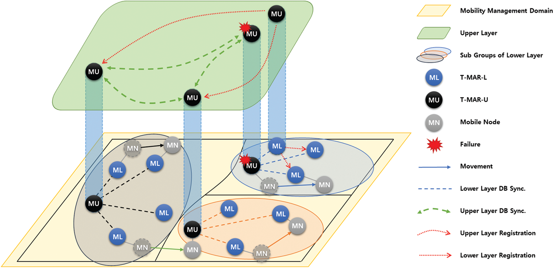
Figure 1: Conceptual architecture of the proposed Proxy-based HDMM

3.2 Operation Procedure of Proxy-Based HDMM
The initial access of the MN and handover within the subgroup are performed in the lower layer. Fig. 2 shows the detailed operation procedure of the lower layer protocol.
In the attachment phase, the T-MAR (T-MAR-L1 in Fig. 2) recognizes the MN's connection and checks the IP to determine whether it is an attachment or a handover. If it is an attachment, the T-MAR updates the MN information in the DB and sends a PBU message to the T-MAR-U. The CoA is not recorded in the DB at this time because the data can be transmitted by the internal routing protocol. Upon receiving the PBU, the T-MAR-U updates the MN's ID, HoA, and CoA in the DB, and it completes the attachment by replying with a proxy binding ack (PBA) message. At this time, the T-MAR-U synchronizes the DB within the group by delivering the updated DB information through a multicast of the LDS message to all T-MARs in the subgroup. When the attachment phase is complete, the CN and MN can transmit and receive data through subnet routing.
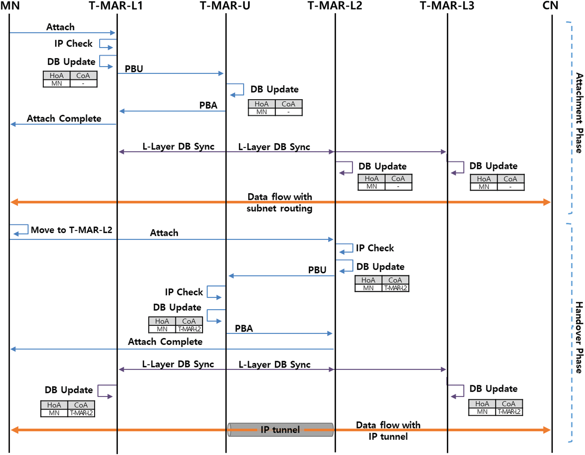
Figure 2: Attachment and handover procedure in the lower layer
The handover phase is performed when an MN moves and accesses another T-MAR. Upon detecting the movement of the MN, the T-MAR (T-MAR-L2 in Fig. 2) checks the IP address of the MN and records the movement information of the MN in the DB. The T-MAR sends a PBU message including the updated DB data to the T-MAR-U. The T-MAR-U checks whether the MN's movement is within the subgroup, updates the DB, and completes the handover by sending a PBA message. Immediately after, T-MAR-U transmits an LDS message through a subgroup multicast to synchronize the updated DB with the T-MARs in the subgroup. Each T-MAR creates a tunnel to the target T-MAR by using the handover information of the DB, and it can directly deliver data packets to the target T-MAR.
In the upper layer, handover is performed for MN movement between subgroups. Fig. 3 shows a detailed operation procedure for performing the handover in the upper layer.

Figure 3: Handover procedure in the upper layer
When an MN located in subgroup T-MAR-U1 moves and connects to T-MAR-L21 in subgroup T-MAR-U2, T-MAR-L21 detects the movement of the MN. T-MAR-L21 updates the DB and sends a PBU message to T-MAR-U2. T-MAR-U2 checks the movement information of the MN and detects that movement has occurred between subgroups. T-MAR-U2 updates the DB and sends a PBU message to T-MAR-U1 with its own address as the CoA. T-MAR-U1 updates the handover between subgroups to the DB and sends a PBA message to T-MAR-U2. Then, the handover is completed by T-MARU2 sending a PBA message to T-MAR-L21. T-MAR-U2 then synchronizes the upper-layer DB through a multicast of UDS messages. The T-MAR-Us receiving the UDS message synchronize the handover between subgroups in their own group through a multicast LDS message. Each of the T-MARs in the T-MAR-U2 subgroup to which the MN has moved can directly transfer data packets to T-MAR-L21 through tunneling. Other T-MARs deliver data packets on the path to T-MAR-L21 via T-MAR-U2.
If a T-MAR-U fails, one of the T-MAR-Ls can take over the role and operate. The T-MAR-U operation procedure is shown in Fig. 4.
When a T-MAR-U failure is recognized, the designated T-MAR-L transmits a lower-layer registration (LLR) message through a subgroup multicast. Each T-MAR-L that receives the LLR updates the T-MAR-U information in the DB and sends a lower-layer registration ack message, including its own subnet information. The designated T-MAR-L changes its role to T-MAR-U and performs a routing update, including subnet information of the subgroups in the TBN. The role change is completed by the T-MAR-U sending an upper-layer registration (ULR) message to other T-MAR-Us using an upper-layer multicast. The T-MAR-Us update the ULR information in the DB.
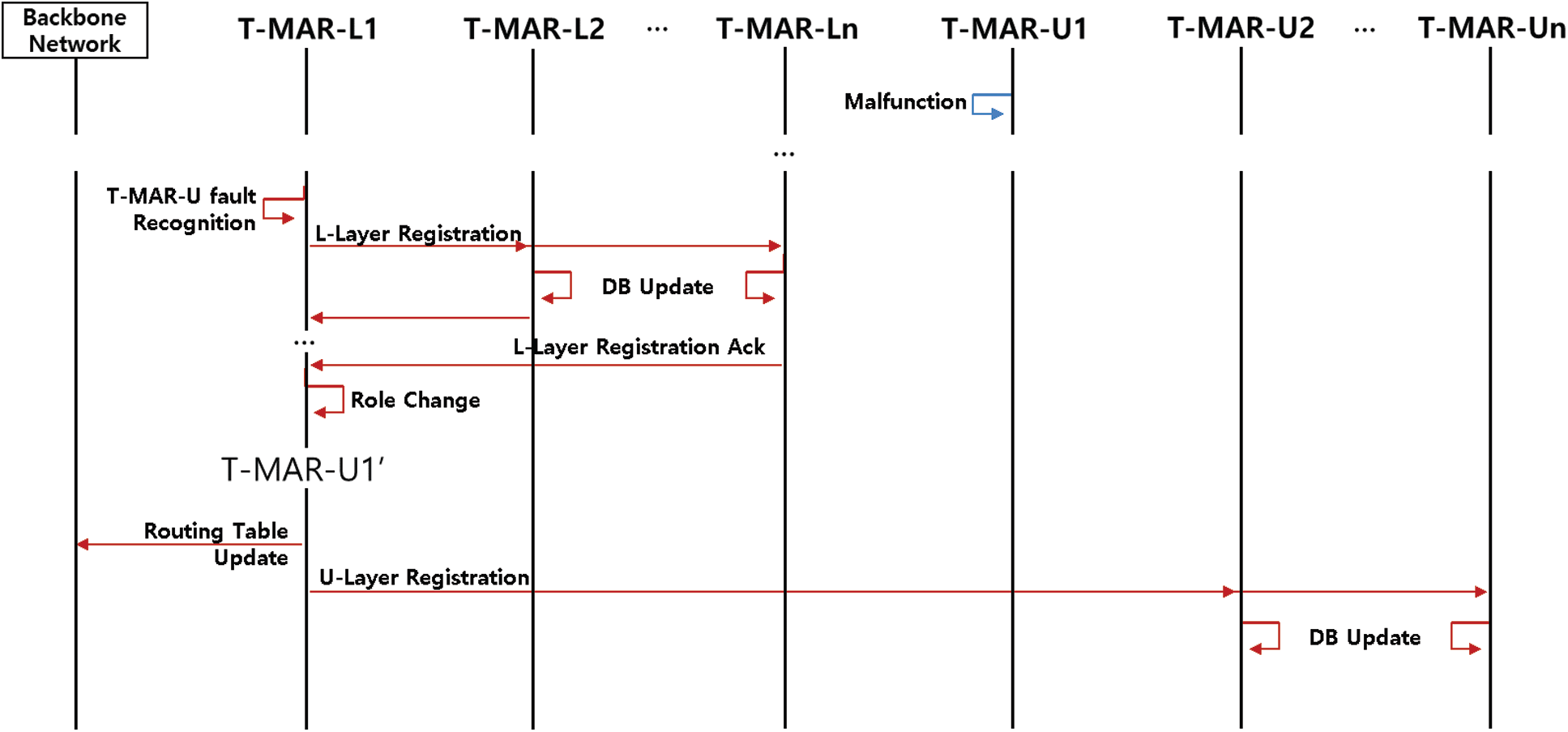
Figure 4: Recovery procedure after a T-MAR-U failure
The designated T-MAR-L is determined in advance by the network plan. The selection method for optimal T-MAR-L designation is out of the scope of this study, but connectivity with other T-MAG-Ls in the group, backbone connection information, and mobility and stability of the T-MAR-L in the operating environment can be considered.
This section analyzes the performance of the proposed Proxy-based HDMM. Performance analysis consists of simple mathematical analysis and M&S analysis using Riverbed Modeler, a network-level simulator.
In this study, the performance of the proposed scheme was compared to the standard MIP, PMIP, and PDMM schemes and PMIP-DMM (from a previous study [23]) schemes through mathematical analysis in four scenarios in which the tactical network structure was considered. The three topologies suggested in the PMIP-DMM were used, and a topology was added to analyze the handover performance between subgroups. The method without consideration of inter-domain movement was applied as a single domain, and the GW closest to the home network was considered as the LMA or CMD.
Fig. 5 shows the network topologies used for performance analysis. Here, we assume that the tactical network is structured in a tree-like form. Fig. 5a is the basic topology in which handover has occurred, and Fig. 5b is a topology where the home and visited network are not directly connected to the GW but connected through a relay router. Fig. 5c is a topology in which CN exists in the same subgroup and the CN-MN path can be optimized. Fig. 5d shows a topology in which movement between subgroups has occurred.
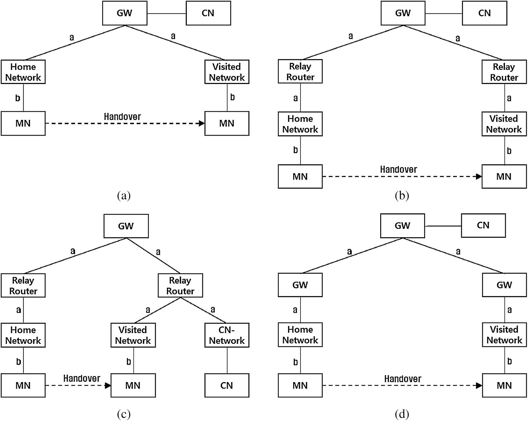
Figure 5: Topology models for analysis: (a) basic topology; (b) relay topology; (c) optimizable topology; (d) subgroup handover topology
The performance analysis model refers to the models from previous studies [29,30]. Here, a simplified model, a level of relative comparison with previous protocols, is applied for ease of analysis. The targets of this analysis are the initial signaling cost CSIG incurred during handover, the cost CPD for delivering packets after handover, and the handover delay DHO, which is the time until data packets are delivered after movement.
The signaling cost CSIG in this analysis can be expressed as follows:
where SMR is the relative ratio of the session arrival rate to the MN mobility rate, CBU is the binding update cost, and CDS is the DB synchronization cost.
CBU is the sum of the transmission cost of all links and the processing cost of all nodes along the path for handover signaling and can be expressed as follows:
where TCa is the signaling message delivery cost of the TBN, TCb is the signaling message delivery cost of the TMN, PCBU is the processing cost of the network node for binding update and tunnel creation, and PCrelay is the processing cost of the network node for relaying signaling messages.
CDS, the cost for DB synchronization, is calculated as follows, considering the number of nodes to be synchronized and the path to each node:
where TCDS is the message delivery cost of the DB synchronization path and PCDS is the synchronization processing cost of the network node. Here, the DB synchronization works only in the TBN, so TCDS is the same as TCa.
The packet delivery cost CPD is calculated for a data transmission path considering the tunneling cost and can be expressed as follows:
where λ is the packet arrival rate, η is the ratio of the data/control packet size, τ is the additional cost rate for tunneling, TCt is the data transmission cost of tunneling, and PCtunnel is the processing cost of encapsulating data for the network node tunneling. In the case of DMM, the transmission paths of the existing and new sessions are classified and applied in a 1:1 ratio. Because tunneling works only in the TBN, TCt is also the same as TCa.
The handover delay DHO can be expressed as the sum of the delay for each signaling path, the delay for each data transmission path, and the DB synchronization delay:
where sl denotes each link in the signaling path, dl denotes each link in the data transmission path, and dsl denotes a link of the synchronization path. Hds is the total number of hops required for DB synchronization message delivery, c is the size of the control message, and d is the size of the data message. Common delays such as node processing delay, L2 switching, and IP connection are excluded from this analysis.
The transmission delay twl(s) for transmitting a packet of size s in a specific link wl is applied as follows:
where qwl is the link failure probability of the wl, Bwl is the link bandwidth of the wl, and Lwl is the delay of the wl.
The parameters and default values used for the performance analysis are shown in Tab. 2. The session-to-mobility ratio and packet arrival rate are variable parameters. The parameters of the TMN compared to the TBN were applied considering that the TMN was composed of a multi-hop ad hoc network. Other parameters used in this analysis were set to typical values by referring to the previous study [29].

Fig. 6 shows the signaling cost of each topology during handover as a function of SMR. The larger the SMR value, the higher the session arrival rate compared to the mobility rate, so the signaling cost for handover decreases. Due to the poor performance of TMN, MIP has the highest signaling cost in all cases except topology (c). PMIP has the lowest signaling cost of all topologies. PDMM shows a slightly higher signaling cost than PMIP due to the PBU/A procedure for creating tunnels between MAARs through CMD. The proposed method and PMIP-DMM have the same binding update cost as PMIP, but the DB synchronization cost is added. The proposed method increases the signaling cost by adding the synchronization cost for upper-layer information sharing, but it is also utilized for data transfer through an efficient path without a routing optimization protocol. When the SMR is small, the ratio of the additional overhead may increase. However, because the distribution of battlefield information is expected to increase in the future, the signaling cost will be relatively low. When MNs move as a group, a further reduction of the signaling cost is possible by performing the synchronization at once [31,32].
Fig. 7 shows the packet delivery cost of each topology as a function of the packet arrival rate. Because of the triangular routing problem and the load on the TMN, MIP has the highest packet delivery cost in all topologies. In the case of PDMM, triangular routing and using the optimal path are applied 1:1, showing an intermediate packet delivery cost. In topologies (a) and (b), PMIP, PMIP-DMM, and the proposed method show the same packet delivery cost. In topology (c), the routing optimization (RO) applying PMIP-DMM and the proposed method show the lowest delivery cost. In topology (d), which uses handover between subgroups, the proposed method shows the most efficient delivery cost. If the packet arrival rate is low, the increase in signaling cost may be greater than the gain from an efficient path. However, as the size and frequency of traffic are expected to increase in future tactical networks, the benefits of efficient routes will also increase.
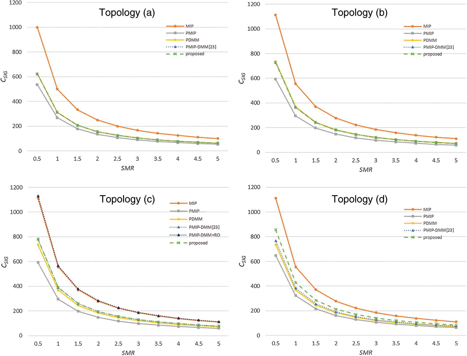
Figure 6: Signaling cost as a function of SMR: (a) graph of basic topology; (b) graph of relay topology; (c) graph of optimizable topology; (d) graph of subgroup handover topology
Tab. 3 shows a comparison of the total cost and the handover latency. The total cost is the sum of the signaling cost and packet delivery cost applying the default parameter values used in this analysis. The handover latency of the PDMM is the delay in the case of triangular routing, which is the existing session, and the handover latency of PMIP-DMM is the delay transmitted to the path before path optimization. In topologies (a) and (b), PMIP shows the lowest cost and the lowest latency. In topologies (c) and (d), the proposed method shows the lowest total cost. The handover latency of the proposed method slightly increases compared to PMIP due to the DB synchronization delay. However, in the case of topology (c), in which it is possible to optimize the routing path, the delay of the proposed method is lower than that of PMIP. This shows that the proposed method is more effective in packet transmission delay than PMIP by selecting an efficient path. Furthermore, PMIP cannot take into account a node failure in the tactical network. The proposed method provides an efficient delivery cost while preparing for a node failure by adding a part of the signaling cost.
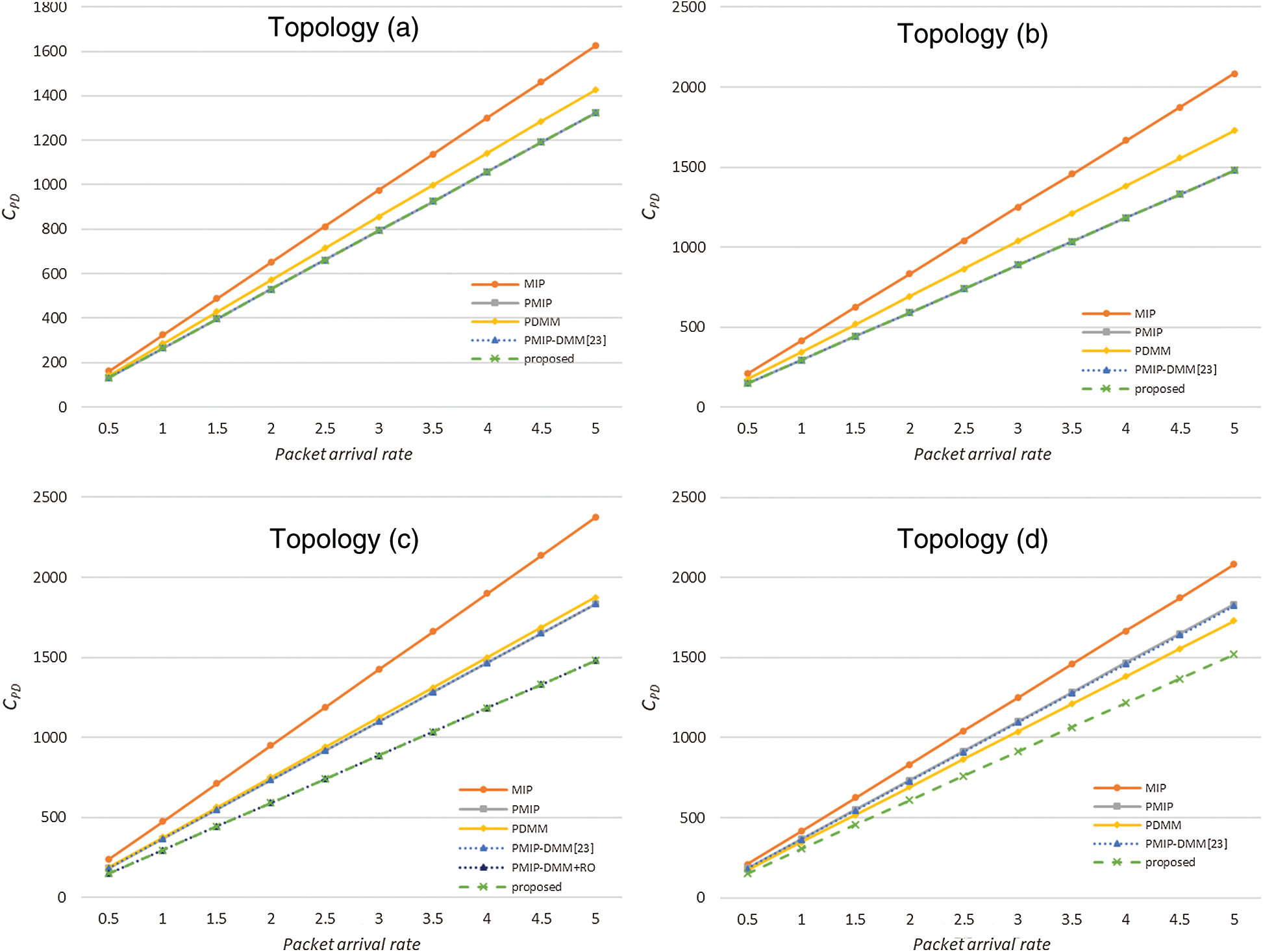
Figure 7: Packet delivery cost as a function of packet arrival rate: (a) graph of basic topology; (b) graph of relay topology; (c) graph of optimizable topology; (d) graph of subgroup handover topology
Additionally, the DB synchronization cost of the FDMM method and the proposed method is compared. The topology used for comparison is shown in Fig. 8a. Considering the characteristics of the tactical network, this comparison assumes that handovers between subgroups and handovers within subgroups occur at a ratio of 2:8.
Fig. 8b shows the comparison result of the synchronization cost according to the number of handovers. FDMM floods the entire network with mobility information when handover occurs, resulting in a high synchronization cost. In the proposed scheme, movements within subgroups are synchronized only to subgroups, and only movements between subgroups are flooded, resulting in a low synchronization cost.

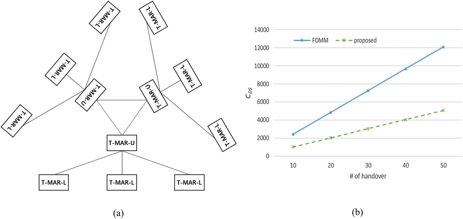
Figure 8: Comparison of database synchronization cost: (a) Comparison topology; (b) Comparison result
M&S was performed using Riverbed Modeler. We designed a virtual operation scenario considering the tactical environment, as shown in Fig. 9. Six units consisting of five MNs were deployed, and one MN of each unit, except for unit 2–1, moved to another unit according to the operational plan. Four movements were intra-subgroup movements, and one movement was an inter-subgroup movement. In each unit, the MNs and the T-MAR constituted a multi-hop (2–4 hop) ad hoc network, with the lower layer composed of two subgroups. In the TBN, relay nodes were arranged considering the mountainous terrain and hierarchical unit structure, and the bottom four nodes of Fig. 9 show only the connection information. MNs periodically transmitted their status information to their superiors, and moving MNs received operation data from their superiors. The arrangement of MNs and nodes irrelevant to the simulation is omitted.
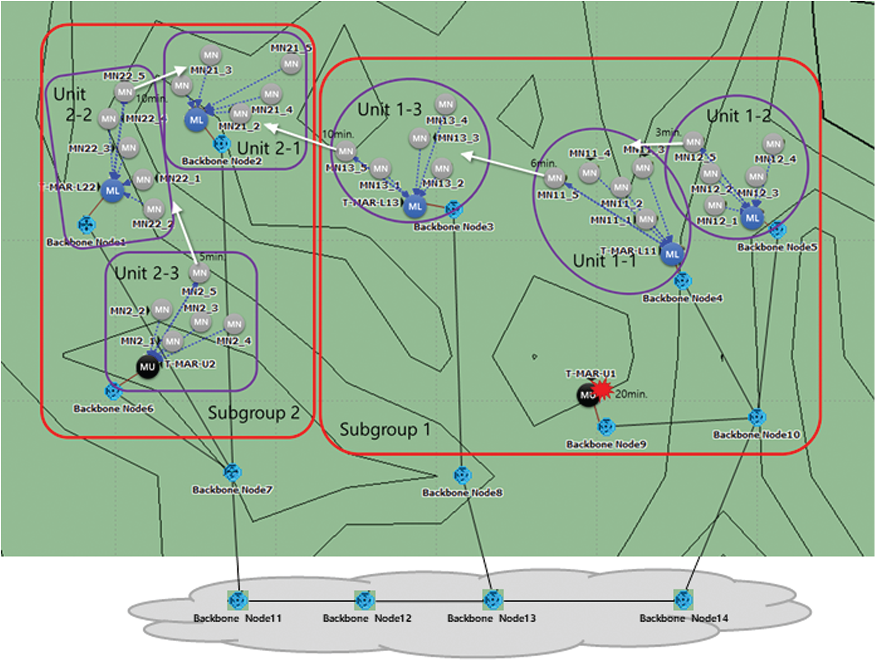
Figure 9: Virtual operation scenario for modeling and simulation
The simulation parameters are given in Tab. 4. The data rates were assumed in consideration of the limited performance of the tactical network, and a basic standard was applied to the MAC/Routing protocol. Because the TBN is also used as a data transmission path for other systems, bidirectional background traffic was applied to each link of the TBN. As an application, periodic status reporting of MNs and transmission of operational data to a moving MN were applied. At 20 min, the destruction of the T-MAR-U1, or the LMA in the case of PMIP, was simulated and compared with a scenario without destruction. The protocols compared were PMIP, PMIP-DMM, and the proposed method.


The backbone overhead, end-to-end delay, and packet delivery ratio (PDR) of each protocol were compared in this M&S. The backbone overhead is the sum of signaling cost and transmission cost by tunneling. Tab. 5 describes M&S results. As studied in the mathematical analysis, the proposed method has the lowest backbone overhead. By using efficient paths, the handover was handled with 60.58% of the backbone overhead required by PMIP and 89.55% of that required by PMIP-DMM. With PMIP, data are passed through the LMA, so it had the largest backbone overhead value with multiple relay nodes. In addition, PMIP most often uses TBN links with background traffic, resulting in a higher delay and lower PDR than the proposed method. Because the proposed method uses the most efficient paths, the delay was 9.78% lower and the PDR was 4.03% higher than with PMIP, and the delay was 2.22% lower and the PDR was 0.49% higher than PMIP-DMM. The performance gap between the proposed method and PMIP-DMM was due to the inter-subgroup handover. Therefore, as the number of inter-subgroup handovers increases, the performance gap will increase. In the node failure scenario, PMIP had a rapidly reduced PDR because MNs cannot communicate with an external terminal or moved MNs if an LMA fails. On the other hand, PMIP-DMM and the proposed method, which can switch major entities, have results similar to those of a failure-free scenario. Therefore, the proposed method is robust to entity failure.
In this paper, we proposed a proxy-based hierarchical mobility management scheme, a mobility-providing technique that reflects the characteristics of the tactical network. To mitigate the loads on the TMN, we defined a new T-MAR, a proxy entity. Through information sharing between T-MARs and role switching of a device in failure situations, continuous movement management is supported without being dependent on a specific entity. In addition, tunneling using shared information makes the data transmission paths efficient without additional signaling. Because of the characteristics of the military structure and operation, the signaling overhead was reduced by dividing the mobility management domain into two layers and subgroups and controlling the transmission range of shared information. Through mathematical analysis and M&S in the assumed tactical network environment, the proposed method proved more effective than existing state-of-the-art methods in overcoming failures, overhead, and delay. The performance analysis results showed that the proposed method is a mobility management protocol suitable for the tactical network environment considered. As a future study, we plan to expand our research into a multi-layered heterogeneous network within tactical networks.
Funding Statement: This work was supported by the Agency for Defense Development.
Conflicts of Interest: The authors declare that they have no conflicts of interest to report regarding the present study.
1. C. Perkins, “IP mobility support for IPv4, revised,” Internet Engineering Task Force, IETF RFC 5944, 2010. [Google Scholar]
2. C. Perkins, D. Johnson and J. Arkko, “Mobility support in IPv6,” Internet Engineering Task Force, IETF RFC 6275, 2011. [Google Scholar]
3. R. Koodli and C. Perkins, “Mobile IPv6 fast handovers,” Internet Engineering Task Force, IETF RFC 5568, 2009. [Google Scholar]
4. H. Jang, J. Jee, Y. Han, S. Park and J. Cha, “Mobile IPv6 fast handovers over IEEE 802.16e networks,” Internet Engineering Task Force, IETF RFC 5270, 2008. [Google Scholar]
5. H. Yokota and G. Dommety, “Mobile IPv6 fast handovers for 3G CDMA networks,” Internet Engineering Task Force, IETF RFC 5271, 2008. [Google Scholar]
6. G. Fairhurst and D. Liu, “Multicast listener extensions for mobile IPv6 (MIPv6) and proxy mobile IPv6 (PMIPv6) fast handovers,” Internet Engineering Task Force, IETF RFC 7411, 2014. [Google Scholar]
7. H. A. Chan, H. Yokota, J. Xie, P. Seite and D. Liu, “Distributed and dynamic mobility management in mobile internet: Current approaches and issues,” Journal of Communications, vol. 6, no. 1, pp. 4–15, 2011. [Google Scholar]
8. H. Chan, D. Liu, P. Seite, H. Yokota and J. Korhonen, “Requirements for distributed mobility management,” Internet Engineering Task Force, IETF RFC 7333, 2014. [Google Scholar]
9. S. Gundavelli, K. Leung, V. Devarapalli, K. Chowdhury and B. Patil, “Proxy mobile IPv6,” Network Working Group, IETF RFC 5213, 2008. [Google Scholar]
10. R. Wakikawa and S. Gundavelli, “IPv4 support for proxy mobile IPv6,” Internet Engineering Task Force, IETF RFC 5844, 2010. [Google Scholar]
11. H. Yokota, K. Chowdhury, R. Koodli, B. Patil and F. Xia, “Fast handovers for proxy mobile IPv6,” Internet Engineering Task Force, IETF RFC 5949, 2010. [Google Scholar]
12. M. Liebsch, A. Muhanna and O. Blume, “Transient binding for proxy mobile IPv6,” Internet Engineering Task Force, IETF RFC 6058, 2011. [Google Scholar]
13. D. Liu, J. C. Zuniga, P. Seite, H. Chan and C. J. Bernardos, “Distributed mobility management: Current practices and gap analysis,” Internet Engineering Task Force, IETF RFC 7429, 2015. [Google Scholar]
14. A. Yegin, D. Moses and S. Jeon, “On-demand mobility management,” Internet Engineering Task Force, IETF RFC 8653, 2019. [Google Scholar]
15. G. Tsirtsis, H. Soliman, N. Montavont, G. Giaretta and K. Kuladinithi, “Flow bindings in mobile IPv6 and network mobility (NEMO) basic support,” Internet Engineering Task Force, IETF RFC 6089, 2011. [Google Scholar]
16. H. Yokota, D. Kim, B. Sarikaya and F. Xia, “Flow bindings initiated by home agents for mobile IPv6,” Internet Engineering Task Force, IETF RFC 7109, 2014. [Google Scholar]
17. C. Bernardos, “Proxy mobile IPv6 extensions to support flow mobility,” Internet Engineering Task Force, IETF RFC 7864, 2016. [Google Scholar]
18. A. Chan, X. Wei, J. Lee, S. Jeon and C. Bernardos, “Distributed mobility anchoring,” Internet Engineering Task Force, IETF RFC 8818, 2020. [Google Scholar]
19. U. Chunduri, J. Kaippallimalil, S. Bhaskaran, J. Tantsura and P. Muley, “Transport network aware mobility for 5G,” Internet Engineering Task Force, IETF draft-ietf-dmm-tn-aware-mobility-00, 2021. [Google Scholar]
20. I. Shayea, M. Ergen, M. Azmi, S. Çolak, R. Nordin et al., “Key challenges, drivers and solutions for mobility management in 5G networks: A survey,” IEEE Access, vol. 8, pp. 172534–172552, 2020. [Google Scholar]
21. J. Tanveer, A. Haider, R. Ali and A. Kim, “Reinforcement learning-based optimization for droneMobility in 5G and beyond ultra-dense networks,” Computers, Materials & Continua, vol. 68, no. 3, pp. 3807–3823, 2021. [Google Scholar]
22. Y. Kim, K. Sun and Y. Kim, “Distributed mobility management scheme for the tactical network,” Journal of Korean Institute of Communications and Information Sciences, vol. 39, no. 11, pp. 1078–1087, 2014. [Google Scholar]
23. K. Sun, Y. Kim, H. Noh, H. Park, M. Han et al., “PMIP-Based distributed mobility management for tactical network,” Journal of the Korea Institute of Military Science and Technology, vol. 22, no. 5, pp. 654–666, 2019. [Google Scholar]
24. K. Sun, Y. Kim, H. Noh, H. Park, M. Han et al., “Mobility management for ILNP-based tactical network,” Journal of the Korea Institute of Military Science and Technology, vol. 23, no. 3, pp. 246–256, 2020. [Google Scholar]
25. R. Atkinson, S. Bhatti and U. S. Andrews, “Identifier-locator network protocol (ILNP) architectural description,” Internet Research Task Force, IRTF RFC 6740, 2012. [Google Scholar]
26. D. Farinacci, V. Fuller, D. Meyer and D. Lewis, “Locator/ID separation protocol (LISP),” Internet Engineering Task Force, IRTF RFC 6830, 2013. [Google Scholar]
27. S. H. Cha, M. Shin, J. H. Ham and M. Y. Chung, “Robust mobility management scheme in tactical communication networks,” IEEE Access, vol. 6, pp. 15468–15479, 2018. [Google Scholar]
28. H. Choi, S. Seo, D. Jung, S. Pack, M. Kang et al., “Design and implementation of integrated tactical mobility testbed,” ICT Express, vol. 7, no. 1, pp. 23–27, 2021. [Google Scholar]
29. C. Makaya and S. Pierre, “An analytical framework for performance evaluation of IPv6-based mobility management protocols,” IEEE Transactions on Wireless Communications, vol. 7, no. 3, pp. 972–983, 2008. [Google Scholar]
30. F. Giust, C. J. Bernardos and A. Oliva, “Analytic evaluation and experimental validation of a network-based IPv6 distributed mobility management solution,” IEEE Transactions on Mobile Computing, vol. 13, no. 11, pp. 2484–2497, 2014. [Google Scholar]
31. P. Thubert, A. Petrescu, R. Wakikawa and V. Devarapalli, “Network mobility (NEMO) basic support protocol,” Internet Engineering Task Force, IRTF RFC 3963, 2005. [Google Scholar]
32. K. Imran, N. Anjum, S. Mahfooz, M. Zubair, Z. Yang et al., “Cluster-based group mobility support for smart IoT,” Computers, Materials & Continua, vol. 68, no. 2, pp. 2329–2347, 2021. [Google Scholar]
 | This work is licensed under a Creative Commons Attribution 4.0 International License, which permits unrestricted use, distribution, and reproduction in any medium, provided the original work is properly cited. |