DOI:10.32604/cmc.2022.019741
| Computers, Materials & Continua DOI:10.32604/cmc.2022.019741 | |
| Article |
High Gain of UWB Planar Antenna Utilising FSS Reflector for UWB Applications
Department of Electronics and Computer Engineering (FKEKK), Center for Telecommunication Research and Innovation (CeTRI), Universiti Teknikal Malaysia Melaka (UTeM), Durian Tunggal, Malacca, Malaysia
*Corresponding Author: Ahmed Jamal Abdullah Al-Gburi. Email: engahmed_jamall@yahoo.com
Received: 23 April 2021; Accepted: 24 May 2021
Abstract: In this paper, a high gain and directional coplanar waveguide (CPW)-fed ultra-wideband (UWB) planar antenna with a new frequency selective surface (FSS) unit cells design is proposed for UWB applications. The proposed UWB antenna was designed based on the Mercedes artistic-shaped planar (MAP) antenna. The antenna consisted of a circular ring embedded with three straight legs for antenna impedance bandwidth improvement. The modelled FSS used the integration of a two parallel conductive metallic patch with a circular loop structure. The FSS provided a UWB stopband filter response covering a bandwidth of 10.5 GHz, for frequencies from 2.2 to 12.7 GHz. The proposed FSS had a compact physical dimension of 5 mm × 5 mm × 1.6 mm, with a printed array of 19 × 19 FSS unit cells. The FSS unit cells were printed on only one side of the dielectric FR4 substrate and placed as a sandwich between the antenna and the reflector ground plane. An equivalent circuit configuration (ECC) was used to verify the FSS unit cell structure’s performance. The simulated results indicated that the UWB MAP antenna and FSS reflector provided a fractional bandwidth of 136% and a high gain of 11.5 dB at 8.5 GHz with an acceptable radiation efficiency of 89%. Furthermore, the gain was improved across the operating band and kept between 8.3 and 11.5 dB. The proposed antenna was in good agreement between theoretical and experimental results and offered a wide enough bandwidth for UWB and vehicle applications.
Keywords: UWB MAP antenna; stable gain; FSS reflector; ECC; stopband response; reflection phase
Throughout the past decade, the demand for high data rate applications, low interference, low complexity, and low power consumption for communication systems has encouraged the need for UWB applications. The significance of this need can be exemplified by the Federal Communication Committee (FCC) certification of the use of the band from 3.1 to 10.6 GHz for UWB applications in 2002 without the need for any licence. The action was also to prevent interference with existing bands [1]. UWB technology permits the spread of extremely short pulses in a wide range of frequencies [2].
To leverage the advantages of this UWB technology, planar monopole antennas have been extensively used due to their excellent characteristics, such as uncomplicated structure, making them easy to fabricate. UWB antennas are commonly implemented with a partial ground plane (PGP) [3,4], and CPW feeds [5,6]. The CPW-fed con-figuration is more preferred since it is easy to fabricate and combine with an integrated circuit board. As radiators usually used in UWB operations, planar antennas have omnidirectional characteristic and two-sided radiation patterns in their principal radiating planes. The drawback of this kind of antenna is that omnidirectional emission leads to high interference and energy loss in unwanted directions, meaning that the main lobe of the radiation pattern is low. Moreover, the back lobe radiation is high and capable of affecting the surrounding environment changes [7–12].
Therefore, under these circumstances, the directional radiation is more favoured as it guarantees more sensible use of the radiated power, which can be explained through a deep analysis related to Effective Isotropic Radiated Power (EIRP) [13]. The pulses of power received (Pr) by the radiator (antenna) are equivalent to the transmitted power (Pt) with the same radiated mechanism. The transmitted gain (Gt) is formed from the transmitted power received from the radiator, as shown by the equation below:
where Pt and Gt are the power and gain transmitted, indicated by the EIRP since most of the power radiated in uniformity in all orientations (gain) with an input power of PtGt as shown in Fig. 1.
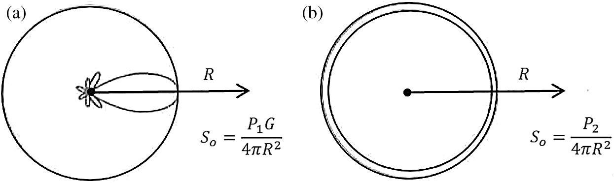
Figure 1: Sketch of the EIRP principle radiation directions: (a) Directional and (b) Omnidirectional [13]
As can be seen from Fig. 1, the two cases can be considered comparable as observed by the power receiver (P) if P2 is assumed to be P2 = P1G, which denotes that the sender directional radiation needs less input power which is equal to 1/G.
Hence, the power limitation required by the FCC can be considered while developing the radiator’s gain by decreasing the input power. Directional radiation offers more extra power saving. These advantages of using directional radiation make it useful for UWB applications, including for vehicle applications [14,15]. A compromise can be performed by employing an antenna with directional radiation where the transmitted power can be efficiently distributed. At the same time, the coverage range will remain a hemispherical space on every side of the antenna. Using UWB technology, the coverage area is good enough for antennas mounted or integrated into vehicular bodies. The displaced back radiation is not of high advantage and will be reflected or absorbed by the vehicles’ bodies anyway. Furthermore, an FSS reflector with ultra-wide stopband properties can enhance the radiation direction and gain of UWB antennas. In other words, appropriately designed UWB reflectors can add directionality to existing UWB omnidirectional antennas.
FSS is a two-dimensional or thin, periodic array that can exhibit its filter characteristics to transmit (bandpass) and/or reflect (stopband) electromagnetic wave (EMW) when triggered by an angle arbitrary to the plane arrays [16]. FSSs have been introduced as UWB reflectors in these studies [17,18]. Moreover, FSSs are subject to frequency selective characteristics, meaning they have a non-similar behaviour over frequency, which give them the ability to serve multiple purposes. They can be employed in antenna engineering as space filters, polarisers, and absorbers [19–21]. Therefore, they have various uses, including for radio telecommunication systems and radar cross-section (RCS) [22,23].
Additionally, FSSs are also comparable to metasurfaces which have similar characteristics in dealing with filtering behaviour and the incident wave of angles. Some metasurfaces were upgraded with different techniques and performed as a metallic reflector to improve the antenna application’s directivity and gain. In [24], an anisotropic metasurface reflector was used to improve the antenna performance. A reflective metasurface (RMS) was proposed to enhance the antenna gain and bandwidth using a double split-ring resonator [25]. Nevertheless, these metallic reflectors cannot provide a stable gain response through the band due to their reflection, which is off.
Therefore, multilayer FSS structures with various resonant frequencies have been utilised to obtain a desirable UWB response. A double-layer FSS is presented in [26], which provided a bandwidth of 10.35 GHz for frequencies from 3.05 to 13.4 GHz with a gain enhancement from 2 to 4 dB. Furthermore, earlier studies have also performed three-layer and four-layer FSS structures [27,28], respectively. Nevertheless, the stacking design still suffers from several disadvantages, including design complexity and a large FSS unit dimension. As a result, the multilayer FSS type is not convenient for miniaturisation and stimulates an economic concern. In addition, obtaining a steady gain through the band is also crucial for such a wideband frequency spectrum where the gain needs to be constant and stable across the operating band.
Several single-layer FSS reflectors have recently been designed to yield a stable gain response in UWB frequencies [29,30]. In [29], the FSS was designed similar to the square loop structure, and the proposed antenna achieved a maximum gain of 9.6 dB with a gain enhancement of 6.2 dB after loading the FSS reflector. A single-layer FSS is presented in [30], which provided a bandwidth of 8.5 GHz for frequencies from 2.5 to 11 GHz and a gain variation of 1.0 dB. In addition, the proposed antenna was fabricated using the Rogers RO4350B substrate, which is an expensive substrate material.
In this paper, a CPW-fed UWB MAP antenna with a single-layer, single-side FSS reflector is proposed for gain enhancement application. A comprehensive parametric study of the proposed antenna with and without the FSS was carried out to determine the best values of its parameters and their impact on the antenna performance. The total electrical dimension of the proposed UWB MAP antenna with the FSS reflector loaded was 2.4 λo × 2.4 λo × 0.038 λo, where λo corresponded to the centre of frequency at 7.2 GHz. The antenna achieved a fractional bandwidth of 136%, with a high gain of about 11.5 dB at 8.5 GHz. A summary of the contribution to the body of knowledge of this paper is listed below:
a) A new shape of the UWB antenna was proposed (MAP antenna), and it achieved a bandwidth of 10.5 GHz from 2.1 to 12.6 GHz, with high efficiency and gain of 97% and 6.7 dB at 9.8 and 8.4 GHz, respectively.
b) Obtained a miniaturised and new shape of FSS unit cell with a total physical dimension of 5 mm × 5 mm × 1.6 mm, with a linear decreasing phase over UWB frequencies.
c) The proposed FSS exhibited UWB stopband response covering a bandwidth from 2.2 to 12.7 GHz. Moreover, the running mechanism of the FSS was verified through an ECC.
d) The proposed MAP antenna with FSS achieved directional radiation and high gain over UWB frequencies with a high gain of 11.5 dB at 8.5 GHz and 8.9 dB at the lowest frequency of 2.2 GHz.
The following is the remaining structure of this paper: Section 2 presents the proposed MAP antenna design strategy; Section 3 presents the proposed FSS unit cell design strategy, including the FSS method analysis, design process and the ECC analysis; Section 4 describes the operational mechanism, fabrication, simulation and measurement of results of the proposed antenna, and Section 5 summarises the study results.
The geometry of the proposed CPW-fed MAP antenna is shown in Fig. 2, with a total physical dimension of 50 mm × 50 mm × 1.6 mm, corresponding to the length (L), width (W), and the FR4 substrate thickness (ht), respectively. The FR4 substrate was used for the simulation process and had an Epsilon (dielectric constant) of 4.5 with a dissipation factor (tan δ) of 0.035. All antenna parameters are listed in Tab. 1.
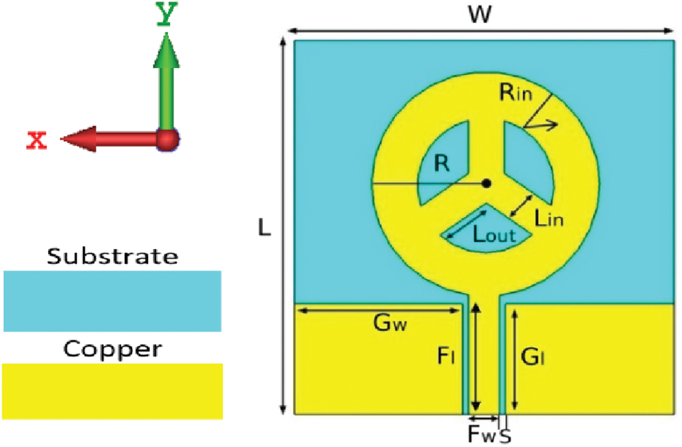
Figure 2: The geometry of the proposed MAP antenna
Regarding the geometry shown in Fig. 2, the following design patterns describe the development of the Mercedes-shaped patch with a demonstrative presentation, as illustrated in Fig. 3.
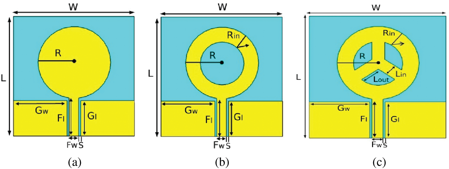
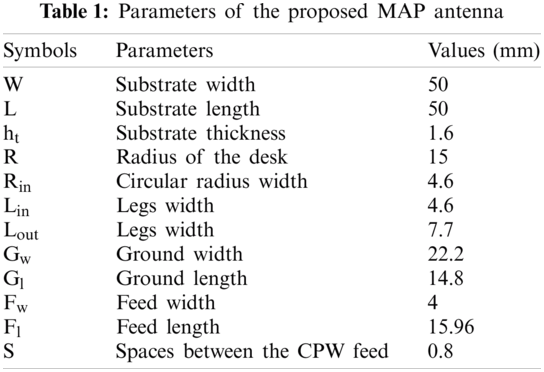
Figure 3: Development of the proposed MAP antenna: (a) Circular disk-shape, (b) Circular ring-shape, and (c) Mercedes-shape
Pattern-1 (M1): The first design phase started from a basic circular disk, and the total antenna dimension was 50 mm × 50 mm × 1.6 mm. The circular disk of radius R with a 50 Ω CPW feed was printed on one side of the FR4 substrate. With a circular disk radius (R) of 15 mm, the diameter (D = 2R) of the disk was found to be 30 mm, which was equal to one-sixth of the wavelength at the first resonant frequency around 19 mm as discussed in [4].
The simulated reflection coefficients (S11) with all three phases are presented in Fig. 4a, where it shows that the antenna with the circular disk pattern had four main resonant frequencies. The frequency band from 3.1 to 3.9 GHz was out of the −10 dB range, which did not incorporate the UWB spectrum. Although the circular disk achieved a high gain of 7.55 dB at 8.6 GHz, the gain varied through the UWB band, as shown in Fig. 4b. Meanwhile, the circular disk pattern achieved a 0.95 radiation efficiency (in linear scale), which was equal to 95%, as shown in Fig. 4c.
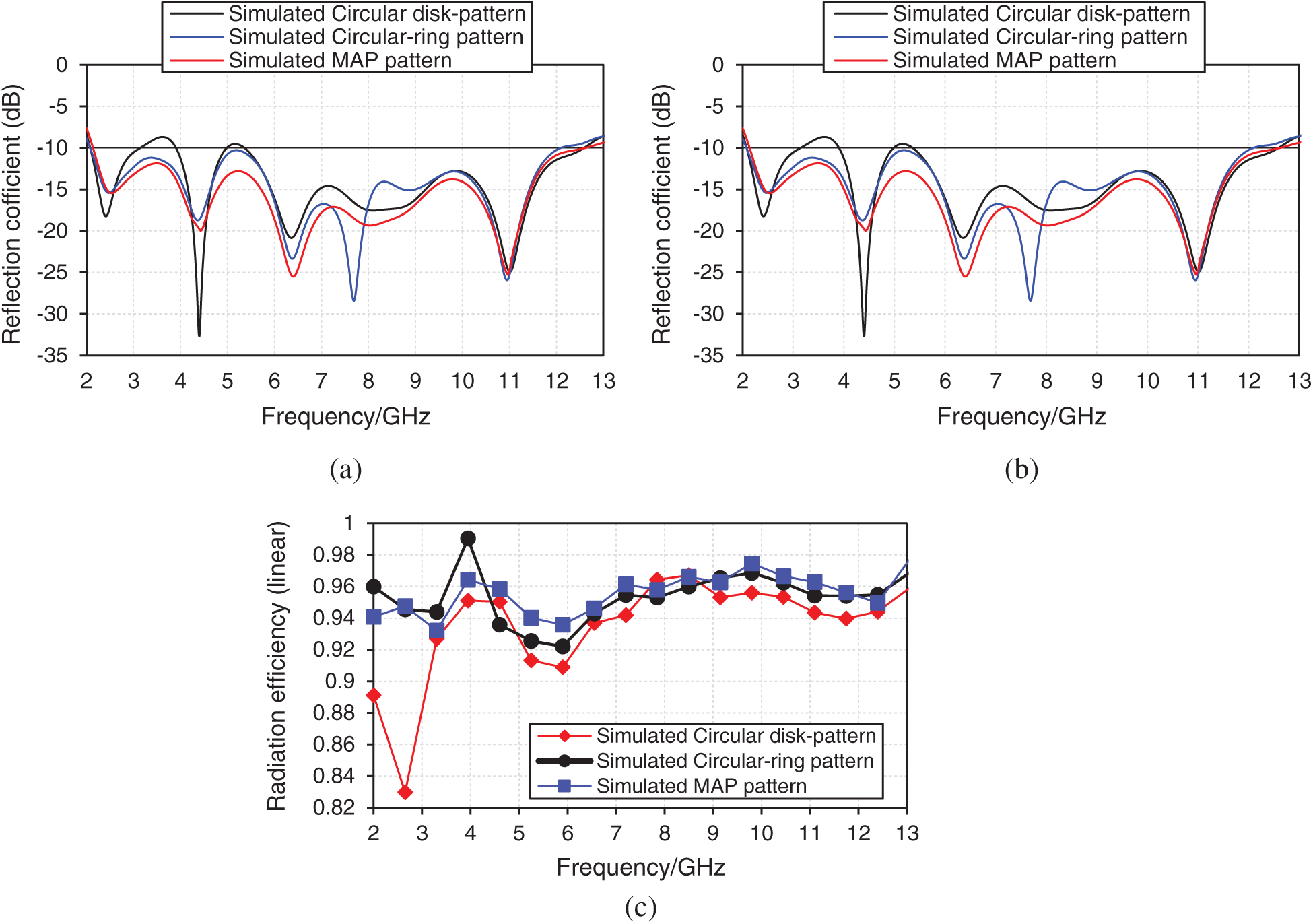
Figure 4: Simulated results of the antenna patterns: (a) Reflection coefficient (S11), (b) Gain (dB), and (c) Radiation efficiency (linear scale)
Pattern-2 (M2): In this phase, the circular ring was formed with maintaining the same substrate dimension as given in M1, where Gl and Gw indicated the length and the width of the FR4 substrate layer. The space of the CPW feed line was fixed at S = 0.8 mm to attain 50 Ω of impedance. The circular ring pattern achieved a wide impedance bandwidth for frequencies from 2.1 to 12.08 GHz. Nevertheless, the UWB frequencies had less resonance through the bands. For example, frequencies from 4.9 GHz up to 5.3 GHz had poor resonances, around −10.1 to −10.3 dB of return loss performance, as shown in Fig. 4a. Hence, high resonances through the band proved advantageous, especially for fabrication and measurement purposes in which the return loss increased due to the fabrication tolerance. As confirmed by Figs. 4b–4c, the circular ring pattern achieved an 8.2 dB of peak gain at 12.8 GHz with 99% of radiation efficiency at 4 GHz.
Pattern-3 (M3): Finally, three straight legs were used to structure the Mercedes-shaped patch pattern, and the Mercedes-shaped patch with the CPW feed served as an impedance matching circuit. Consequently, by changing the space between the CPW and the feed line, the input impedance was tuned, hence the 10 dB return loss bandwidth. Figs. 4a–4b demonstrate the CPW-fed UWB MAP antenna reflection coefficient and gain, respectively. The proposed antenna obtained a wide range frequency from 2.1 to 12.6 GHz with a better return loss performance of −13.5 dB at 5.2 GHz with a peak gain of 6.7 dB at 8.4 GHz. Meanwhile, it can also be concluded that the gain was more stable through the UWB frequencies, unlike those for the circular disk and circular ring patterns. Moreover, the UWB MAP antenna exhibited a high radiation efficiency of 0.97 at 9.8 GHz (in linear scale), around 97% in the operating band, as shown in Fig. 4c.
3 Proposed FSS Unit Cell Design Strategy
3.1 FSS Unit Cell Analysis Method
Periodic boundary conditions (PBCs) allow the effect of the periodic replication of periodic structures to be modelled by simulating only a single unit cell. Applying PBCs are necessary for infinite structures where the perfectly matched layers cannot be used because these conditions are compatible only with finite structures such as antennas. FSSs are a typical example of the periodic structures that can be effectively simulated using PBCs.
Different setups were proposed to model periodic structures through the CST MWS simulator. One approach surrounded a single unit cell with PBCs and used waveguide ports to calculate the reflection, transmission magnitude, and phase. Another method consisted of using a combination of a perfect electric conductor (PEC) and perfect magnetic conductor (PMC) boundary conditions along with waveguide ports, as in Fig. 5a. The third setup used the unit cell boundary conditions along with Floquet ports to analyse periodic structures. The latter is depicted in Fig. 5b.
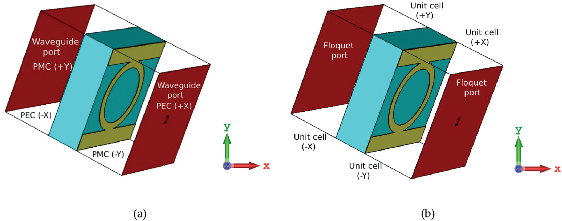
Figure 5: Setups for the simulation of periodic structures using CST MWS: (a) Combination of PEC and PMC, and (b) Unit cell boundary conditions with Floquet ports
3.2 FSS Design Process and Characterisation
In this study, the concept of joining two structures was adopted due to the structures’ abilities to resonate at a relative frequency to develop an FSS with UWB stopband filter properties. At the same time, the structures’ geometries and sizes allowed them to be combined. Hence, finding structures was the first step to design the proposed FSS. In addition, loop models are the best choice as they resonate when their perimeter is approximately a wavelength and their circumferences are good enough to be integrated with other structures. The proposed FSS consisted of a circular loop, which resonates when its circular parties get a part of the wavelength (λ/3), connected to two metallic patches, and their geometries are presented in Fig. 6. The FR4 material was used to print the proposed FSS, and the substrate had a dielectric constant of 4.5 with a thickness of 1.6 and 0.02 tangent loss.
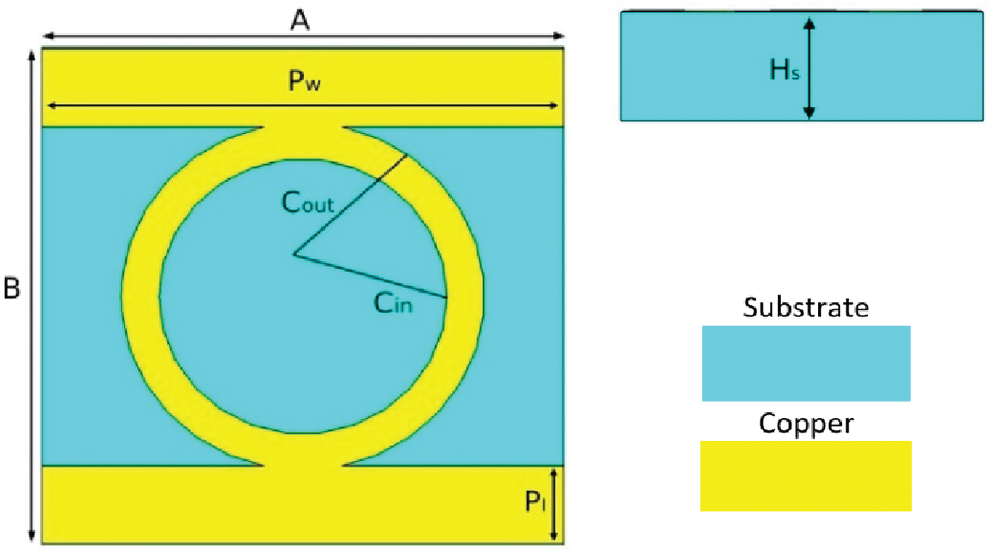
Figure 6: The geometry of the proposed FSS
A parametric study of the proposed FSS is performed in Fig. 7, and it was mainly developed within three rounds of the design process. The modelled unit cell contained two metallic patches connected with a circular loop. The resonant frequency of the proposed FSS depended on the structure’s perimeter, which corresponded to λo at the centre frequency of 7.45 GHz, as displayed in Fig. 7a. A single metallic patch was added and attached to the circular loop geometry. This metallic patch, along with the stationed circular ring, essentially helped deliver stopband operation from 7 GHz up to 14 GHz, as presented in Fig. 7b. The last round was to integrate the circular ring with the two metallic patches. From the simulated results, it was clear that the proposed FSS successfully performed stopband characteristics through UWB frequencies at 6.2 GHz from 2.2 to 12.7 GHz, with a reflection value of 0 dB. The transmission magnitude was less than −10 dB, as presented in Fig. 7c.
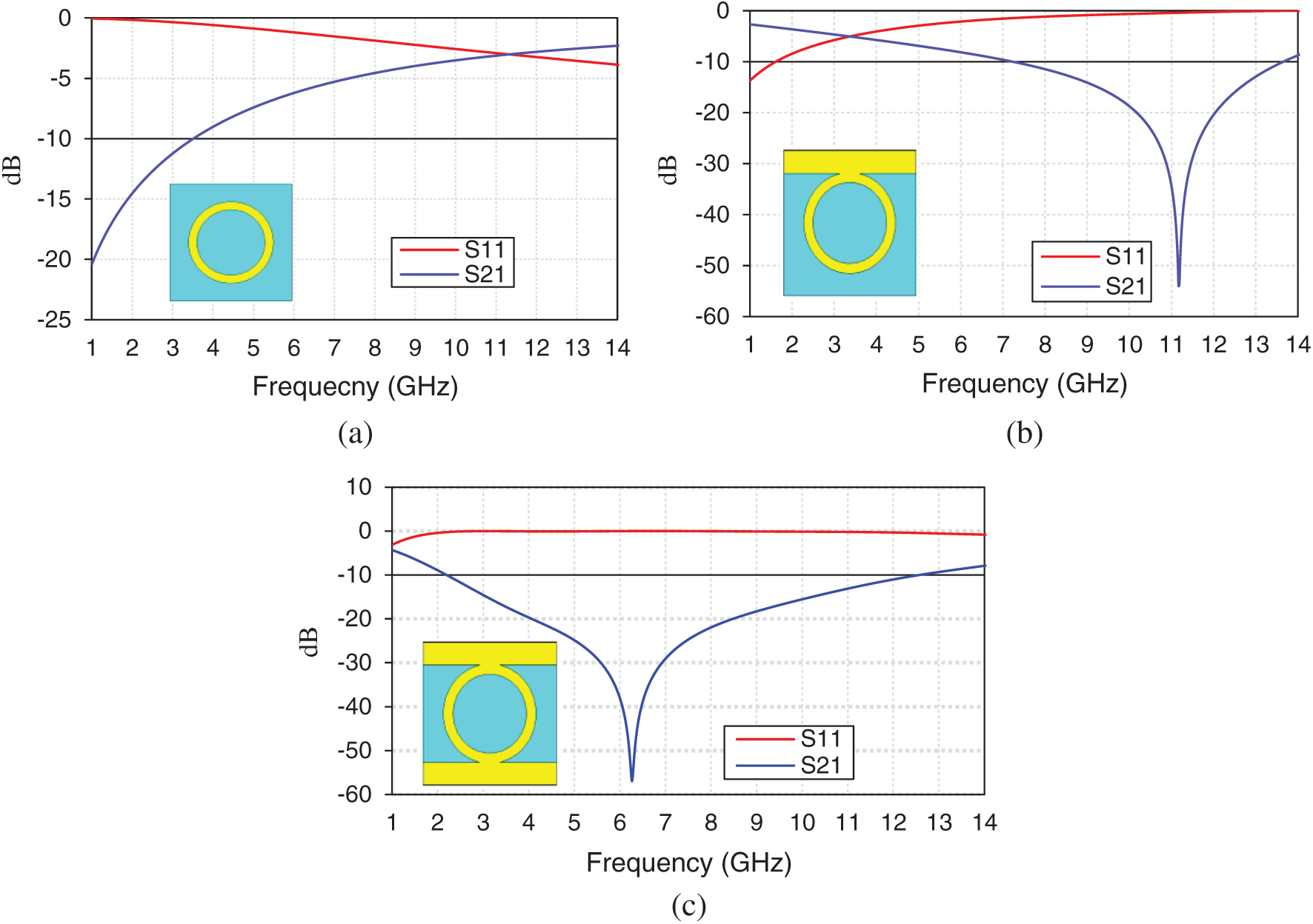
Figure 7: Simulation process of the proposed FSS: (a) Circular loop, (b) Circular loop with a single metallic patch, and (c) Circular loop with two metallic patches
The total physical dimension of the modelled FSS was 5 mm × 5 mm × 1.6 mm (A × B × Hs). The metallic patch width (Pw) was 5 mm, and its length (Pl) was 0.78 mm. An investigation with a comprehensive analysis of the modelled FSS circular loop is presented next.
The circular loop consisted of two essential parameters: “Cin” and “Cout”, and these two parameters indicated the edge of the inner and the outer of the circular loop, respectively. Fig. 8 presents the analysis of parameters “Cin” and “Cout” modification effects, which showed that the circular loop corresponded to the modification of its parameters in a comparable form to the conventional square loop. Additionally, the outer radius was fixed at 1.75 mm.
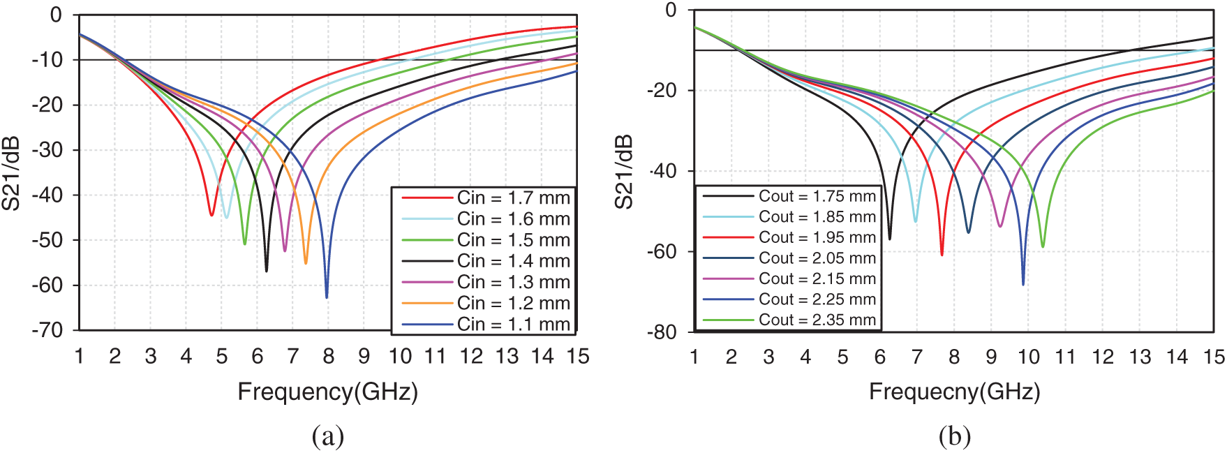
Figure 8: Parametric analysis of the proposed circular loop transmission coefficient: (a) Various values of inner circular loop and (b) Various values of outer circular loop
Fig. 8a shows the effect of different values of “Cin” in which the resonant frequency decreased as the inner circular loop value increased. For example, at 1.7 mm inner circular radius, the stopband response at 4.8 GHz was inadequate compared to other frequencies. As a result, the inner circular radius at 1.7 mm was considered inadequate and thin, and its thickness was made thicker by decreasing the values of the inner ring. Moreover, the stopband response became wider as the inner loop’s thickness increased, as can be seen at 1.1 mm of the inner circular radius. Eventually, the optimum inner radius of 1.4 mm was chosen at 6.3 GHz (which is the black colour).
On the other hand, Fig. 8b presents the effect of the outer circular loop for various numbers of “Cout”, with the inner radius fixed at 1.7 mm. Developing the outer circular radius led to shifting the resonant frequency to the highest and resulted in wider bandwidth. The optimum outer radius of 1.75 mm was chosen at 6.3 GHz (which is the black colour).
From the aforementioned findings, it can be established that a narrow bandwidth was expected as the inner circular loop became smaller. Likewise, as the outer circular loop became larger, a wider bandwidth with movable resonant frequency was realised. Therefore, it can be concluded that the resonance frequency of the FSS was dependent on the perimeter of its geometry.
The outcomes of the earlier processes assisted in delivering a clear picture of the FSS to act as a stopband as follows:
• Combining the two structures was a great idea that can be used to achieve a stopband response.
• The external edge of the circular ring loop controlled the lower side of its working band.
• The internal radius of the circular loop can be used to establish the coveted all higher frequency.
The linear decreasing of the reflection phase of the proposed FSS was observed over the entire frequency of 2.2 to 12.7 GHz. As a result, this important attribute increased the usability of the FSS to carry a variety of applications where a linearly declining phase is needed, as presented in Fig. 9.
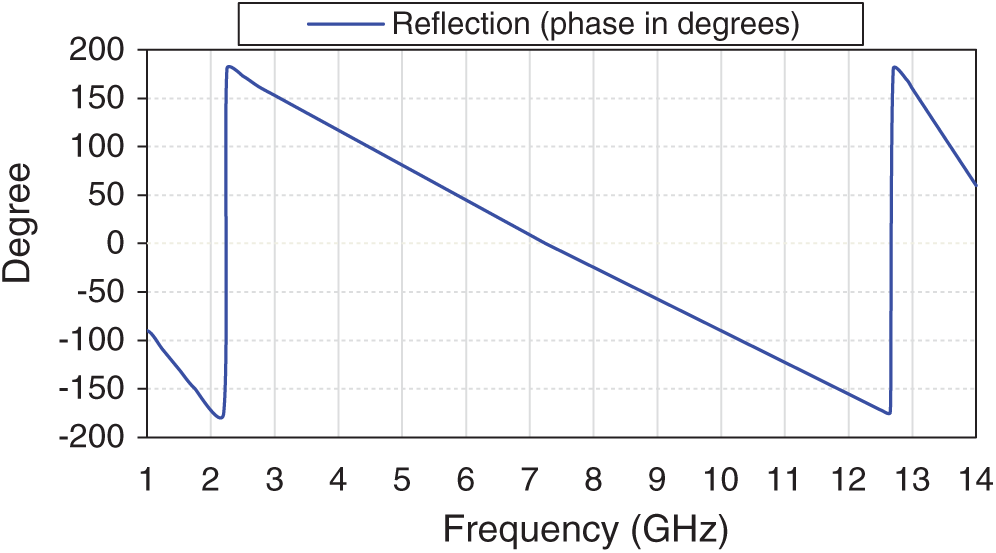
Figure 9: Simulated reflection phase
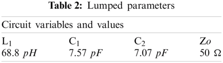
The Advanced Design System (ADS) software was used to design the equivalent circuit. The ECC was formed based on the FSS unit cell structure, and afforded inductance (L) and capacitance (C) lumps in the equivalent circuit. In addition, it was modelled based on LC components combined in series (loading 50 Ω), as displayed in Fig. 10. The stopband response was resonating at 6.2 GHz, as presented in Fig. 7c, whereas the load was close to the unit cell’s radiation resistance. The input resistance of the equivalent circuit at the stopband was best while its input reactance almost disappeared. As a result, the two metallic patches were produced from the inductance L1, C1, and C2 from the gaps inside and outside the circular ring.
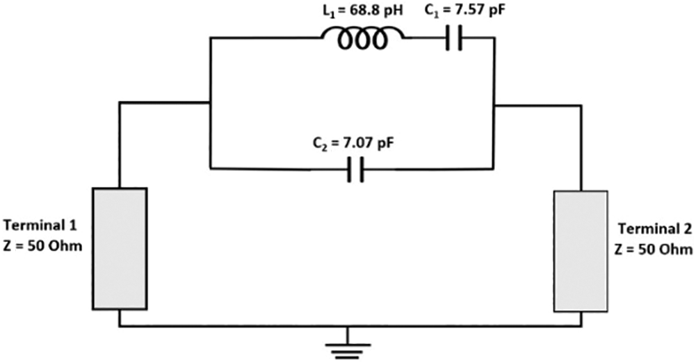
Figure 10: ECC lump formation
The vacuum on both ports of the FSS unit structure was represented as a feed line with a neural impedance of Zo = 50 Ω. In addition, the neural impedance of the FR4 substrate was represented by
As aforementioned, the proposed FSS achieved a stopband response at 6.2 GHz, and its lumped derived in Eq. (2).
The values of the variables ωp1, and ωp2 were the swivel (pole) and zeros pair. Meanwhile, the value of ωp1 was taken to be zero. These variables were realised from Eqs. (3)–(5). The lumped values recorded in Tab. 2 were estimated using the equations mentioned earlier.
4 Proposed Antenna with FSS Reflector
4.1 Operational Mechanism of the Proposed Antenna with the FSS Reflector
Theoretical explanation of the proposed antenna and the FSS reflector with a graphical presentation of the working principle is given by Fig. 11a. Two plane surface waves are described and presented as follows. The first surface plane (OV) indicated the overall incident wave from the antenna and the reflector at a phase of φOV. While the second surface plane (F) presented the incident waves coming from the FSS reflector at a phase of φF. When the reflector was located at a gap (G) in mm below the antenna, the incident waves along the FSS were reflected. These reflected waves towards the FSS unit cells were added to the radiating incident wave coming from the antenna and created a constructive interference indicated as φR. As expected, the gain was at the maximum level when these two waves were in phase with decreasing frequency. The theory for this phenomena is described in the following equation:
Additionally, the overall reflection (φOV) should be approximately zero at all range of frequencies. A set of 19 × 19 FSS unit cells were used to develop the proposed reflector, and their geometries are presented in Fig.11b.
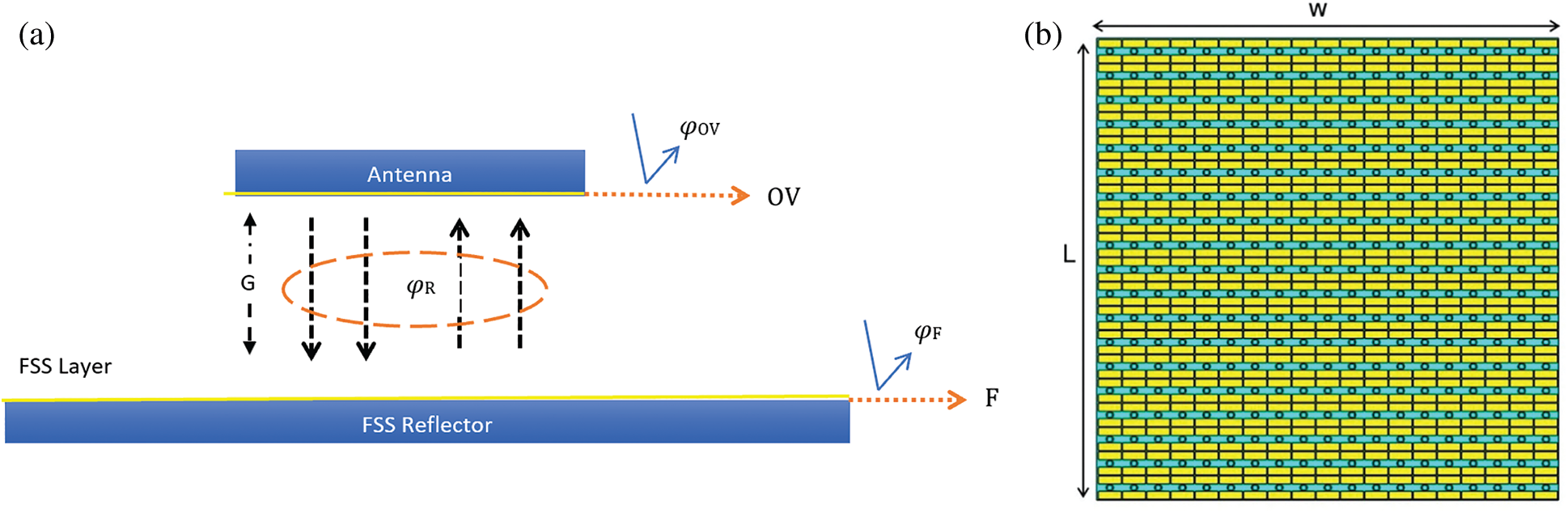
Figure 11: Operational mechanism of the proposed antenna with FSS reflector: (a) Theoretical explanation of proposed antenna and FSS reflector, (b) Geometries of FSS unit cells
4.2 Fabrication and Results Measurement of the Finalised Antenna
The proposed antenna and the FSS reflector were fabricated, with a total physical dimension of 100 mm × 100 mm × 1.6 mm (their photographs are shown in Fig. 12, using the FR4 substrate with a 4.5 dielectric constant. The measurement operation was carried out within four cases, such as the reflection coefficient (S11), gain (dB), efficiency (%) and radiation patterns. The simulated reflection coefficient for the proposed antenna with the FSS reflector obtained a bandwidth of 9.81 GHz for frequencies from 2.29 to 12.1 GHz. Fig. 13 illustrates the simulation and measurement performance of the proposed antenna, with and without the FSS reflector, to visualise the improvement produced by the reflector.
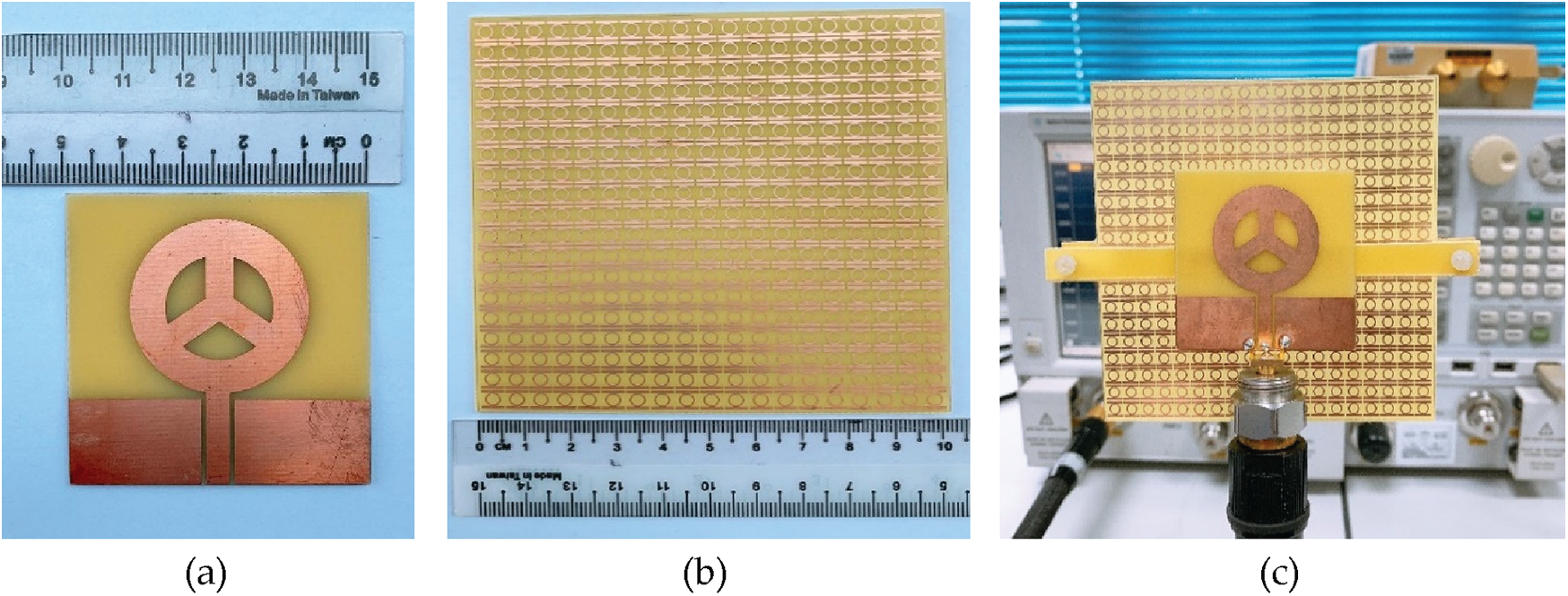
Figure 12: Fabricated prototypes: (a) UWB MAP antenna, (b) FSS reflector, and (c) UWB MAP antenna with FSS reflector
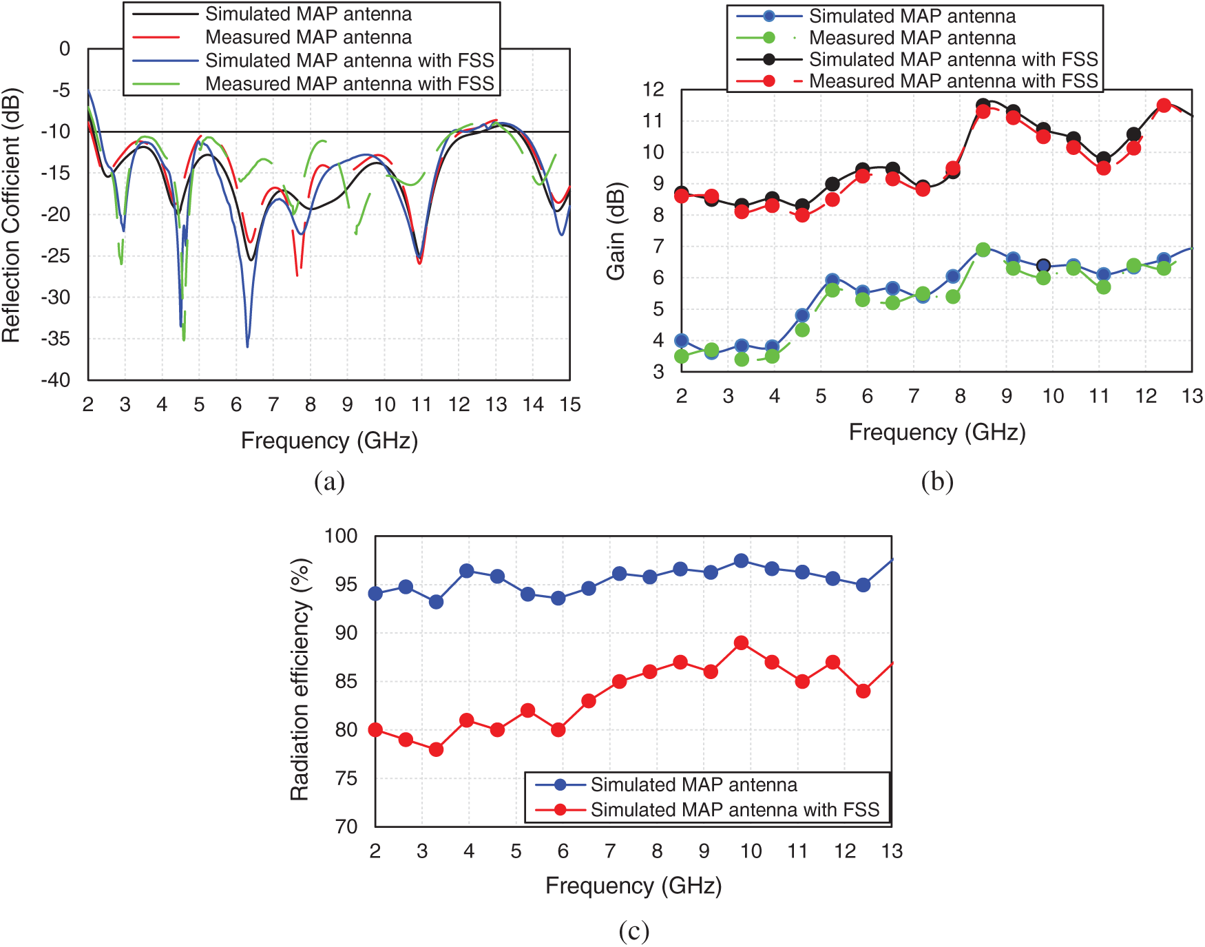
Figure 13: Simulated and measured results of the proposed antenna with FSS reflector: (a) Reflection coefficient (S11), (b) Gain, and (c) Radiation efficiency
Fig. 13a presents the reflection coefficient (S11) of the proposed CPW-fed UWB MAP antenna mounted above the proposed FSS reflector. The results indicated that a reflection magnitude of less than −10 dB was obtained simultaneously through the UWB band with different variations. The measured antenna with FSS achieved a bandwidth of 9.7 GHz for frequencies from 2.2 to 11.9 GHz, which covered the UWB frequencies and beyond. Furthermore, the marching band was performed for an overall profile thickness of 10 mm, around λ/4 at the centre operating frequency of 7.1 GHz. While Fig. 13b demonstrates the simulated and measured gain over the frequency. It can be observed that a high gain of 11.3 dB was obtained at 8.5 GHz after loading the FSS reflector. As for the radiation behaviour, the directivity and the gain of the proposed antenna over the UWB frequency were improved. It was also found that its directivity and gain were greater over higher frequencies of the operating band but minimal over lower frequencies. This behaviour was due to the dimension of the FSS taken, which was smaller in the latter circumstance. Nevertheless, a quasi-stable gain with a peak gain of 11.3 dB over the UWB operating band was significantly provided. The high quasi-stable gain attained was contributed by several factors, such as the linearly decreasing reflection phase over the frequency of the proposed FSS and the small gap between the FSS and the radiator, which cannot be achieved by utilising a metallic reflector [24,25]. As a result, a low profile planar UWB antenna with an improved quasi-stable gain was achieved. It was also observed that the antenna above the reflector gave a similar function, except for small variations, across the entire UWB frequencies. Apart from that, the radiation efficiency of the proposed antenna with and without the single-layer FSS reflector is presented in Fig. 13c. From the graph, it is clear that the efficiency of the UWB MAP antenna alone delivered a higher efficiency of 97% at 9.8 GHz, compared with the FSS reflector integration, which was only 89% at the same resonant frequency of 9.8 GHz. Thus, it can be concluded that the radiation efficiency was reduced with the FSS reflector integration. Furthermore, the small drop in efficiency had grown in the resonance frequencies of the FSS reflector, and this efficiency reduction can be attributed to impedance matching and thermal (dielectric and surface wave) losses.
The finalised MAP antenna and FSS reflector were placed in an anechoic chamber, as shown in Fig. 14, to measure its radiation patterns.
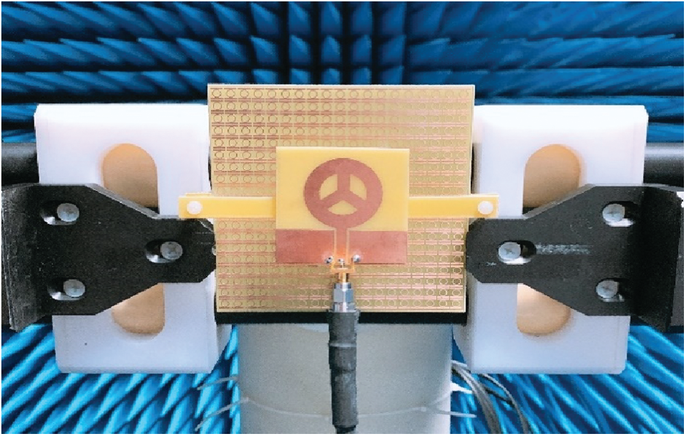
Figure 14: Setup for measuring the finalised antenna in a radiation chamber
Furthermore, the simulated and measured radiation patterns in the E and H planes, corresponding to (YZ) and (XZ), are shown in Fig. 15. The patterns indicated the functional impacts of the FSS reflector on the radiation performance of the antenna and verified the gain enhancement, primarily due to the small back lobe radiation. With the integration of the FSS reflector, the antenna’s backward radiation was decreased, and in contrast, its forward radiation was improved. Evidently, the directivity of the antenna was significantly enhanced by the introduction of the FSS reflector.
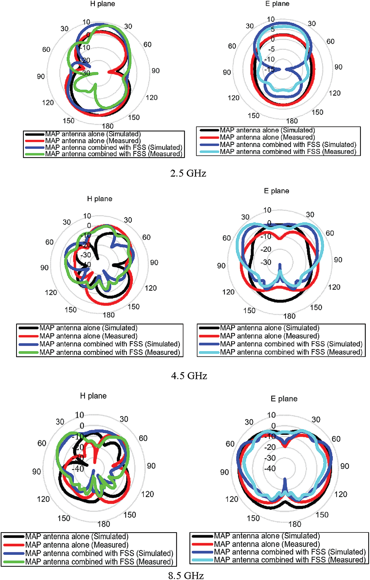
Figure 15: Radiation patterns in E-plane and H-plane at various frequencies
This can be further explained by the standard behaviour of UWB planar antennas, in which the radiation patterns start to change with multiple side lobes due to the distortion and anticipated radiation angle of the used antennas. Nevertheless, the proposed FSS reflector was able to maintain the peak gain despite the radiation distortion at higher frequencies.
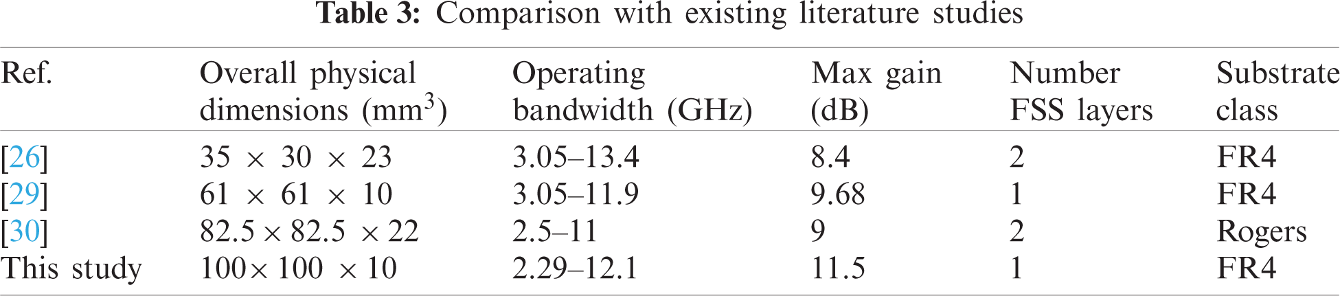
Fig. 16 demonstrates the surface current distribution of the proposed antenna with the FSS reflector separately. As observed, the rainbow colour mapping fields showed a great current flow density for the resonant frequency at 6.2 GHz. From Fig. 16a, the current was mainly disturbed along with the Mercedes radiating patch and more about the feed line, indicating the first resonant frequency. The effect of the current on the FSS unit cell is displayed in Fig. 16b. The dimension of the FSS mainly affected the radiating antenna patch and became more saturated in its particular fields, as indicated in Fig. 16c. In terms of high gain and low profile, the proposed antenna has a high peak gain and low profile compared to all the antennas recorded in Tab. 3. The finalised antenna provides operating bandwidth ranges from 2.29 to 12.1 GHz, which offers more extended bandwidth than antennas proposed in [26,29,30].
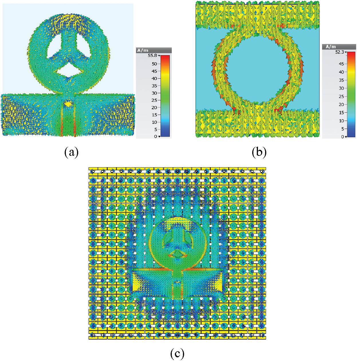
Figure 16: Surface current of the proposed (a) MAP antenna, (b) FSS unit cell and, (c) MAP antenna with FSS
A novel UWB MAP antenna with a new FSS reflector design to improve the antenna’s gain and directionality was proposed. The total physical dimension of the FSS reflector along with the antenna was 100 mm × 100 mm × 1.6 mm. Moreover, a miniaturised and new FSS unit cell with stopband filter characteristics covering a bandwidth of 10.5 GHz for frequencies from 2.2 to 12.7 GHz, with linearly declining phase magnitude over the frequency was obtained. As a result, the directivity and UWB spectrum gain were enhanced for the UWB MAP antenna integrated with the FSS reflector. Nevertheless, the gain was improved with varying enhancements according to frequency ranges. For example, an 8.3 dB gain was obtained for ground-penetrating radar (GPR) applications (3 GHz), and the gain was maintained between 8.4 dB to 8.8 dB for 5G frequencies (3.5–5 GHz). While for C-band applications (4–8 GHz), the gain was sustained between 8.55 dB to 9.9 dB. Therefore, it can be concluded that the proposed antenna exhibited great features and performance to be used for UWB and vehicle applications.
Funding Statement: We would like to thanks to Ministry of Higher Education and UTeM through FRGS Grant F00430 FRGS/1/2020/FKEKK-CETRI/F00430 that support this research.
Conflicts of Interest: The authors declare that they have no conflicts of interest to report regarding the present study.
1. First Report and Order: ‘Revision of part 15 of the commission’s rules regarding ultra-wideband transmission systems’. FCC 02-48, February 2002. [Google Scholar]
2. F. Zeng and J. Yao, “An approach to ultrawideband pulse generation and distribution over optical fiber,” IEEE Photonics Technology Letters, vol. 18, no. 7, pp. 823–825, 2006. [Google Scholar]
3. J. N. A. Jan, S. H. Kiani, D. A. Sehrai, M. R. Anjum, A. Iqbal et al., “Design of a compact monopole antenna for UWB applications,” Computers, Materials & Continua, vol. 66, no. 1, pp. 35–44, 2021. [Google Scholar]
4. J. Liang, C. C. Chiau, X. Chen and C. G. Parini, “Study of a printed circular disc monopole antenna for UWB systems,” IEEE Transactions on Antennas and Propagation, vol. 53, no. 11, pp. 3500–3504, 2005. [Google Scholar]
5. S. Chaimool and K. L. Chung, “CPW-fed mirrored-L monopole antenna with distinct triple bands for WIFI and WiMAX applications,” Electronics Letters, vol. 45, no. 18, pp. 928–929, 2009. [Google Scholar]
6. A. Haider, M. Rahman, H. Ahmad, M. NaghshvarianJahromi, M. T. Niaz et al., “Frequency-agile WLAN notch UWB antenna for URLLC applications,” Computers, Materials & Continua, vol. 67, no. 2, pp. 2243–2254, 2021. [Google Scholar]
7. N. A. Jan, S. H. Kiani, F. Muhammad, D. A. Sehrai, A. Iqbal et al., “V-shaped monopole antenna with chichena itzia inspired defected ground structure for UWB applications,” Computers, Materials & Continua, vol. 65, no. 1, pp. 19–32, 2020. [Google Scholar]
8. A. J. A. Al-Gburi, I. M. Ibrahim and Z. Zakaria, “Band-notch effect of U-shaped split ring resonator structure at ultra wideband monopole antenna,” International Journal of Applied Engineering Research, vol. 12, no. 15, pp. 4782–4789, 2017. [Google Scholar]
9. V. N. K. R. Devana and A. M. Rao, “A compact flower slotted dual band notched ultrawideband antenna integrated with Ku band for ultrawideband, medical, direct broadcast service, and fixed satellite service applications,” Microwave and Optical Technology Letters, vol. 63, no. 2, pp. 556–563, 2021. [Google Scholar]
10. N. Rahman, M. T. Islam, Z. Mahmud and M. Samsuzzaman, “The broken-heart printed antenna for ultrawideband applications,” IEEE Antennas and Propagation Magazine, vol. 60, no. 6, pp. 45–51, 2018. [Google Scholar]
11. R. N. Tiwari, P. Singh and B. K. Kanaujia, “Small-size scarecrow-shaped CPW and microstrip-line-fed UWB antennas,” Journal of Computational Electronics, vol. 17, no. 3, pp. 1047–1055, 2018. [Google Scholar]
12. I. M. Ibrahim, A. J. A. Al-Gburi, Z. Zakaria and H. A. Bakar, “Parametric study of modified U-shaped split ring resonator structure dimension at ultra-wide-band monopole antenna,” Journal of Telecommunication, Electronic and Computer Engineering, vol. 10, no. 2–5, pp. 53–57, 2018. [Google Scholar]
13. D. M. Pozar, Microwave and RF Design of Wireless Systems. New York, USA: John Wiley & Sons, 2000. [Google Scholar]
14. S. M. Patole, M. Torlak, D. Wang and M. Ali, “Automotive radars: A review of signal processing techniques,” IEEE Signal Processing Magazine, vol. 34, no. 2, pp. 22–35, 2017. [Google Scholar]
15. B. D. Pell, E. Sulic, K. Ghorbani, S. John and W. S. T. Rowe, Advancements in Automotive Antennas. Princeton, New Jersey, USA: Citeseer, 2011. [Google Scholar]
16. R. Mittra, C. H. Chan and T. Cwik, “Techniques for analysing frequency selective surfaces-a review,” Proc. of the IEEE, vol. 76, no. 12, pp. 1593–1615, 1988. [Google Scholar]
17. S. S. Sampath and R. Sivasamy, “A single-layer UWB frequency-selective surface with band-stop response,” IEEE Transactions on Electromagnetic Compatibility, vol. 62, no. 1, pp. 276–279, 2018. [Google Scholar]
18. R. Yahya, A. Nakamura and M. Itami, “Compact UWB frequency selective surface with high angular stability,” IEICE Communications Express, vol. 5, no. 2, pp. 39–43, 2016. [Google Scholar]
19. A. J. A. Al-Gburi, I. M. Ibrahim, M. K. Abdulhameed, Z. Zakaria, M. Y. Zeain et al., “A compact UWB FSS single layer with stopband properties for shielding applications,” Przegląd Elektrotechniczny, vol. 2, no. 34, pp. 167–170, 2021. [Google Scholar]
20. M. Fartookzadeh and S. H. M. Armaki, “Enhancement of dual-band reflection-mode circular polarisers using dual-layer rectangular frequency selective surfaces,” IEEE Transactions on Antennas and Propagation, vol. 64, no. 10, pp. 4570–4574, 2016. [Google Scholar]
21. K. Xue, H. Zhai, S. Li and Y. Shang, “A miniaturised absorber frequency selective surface with good angular stability,” IEEE Antennas and Wireless Propagation Letters, vol. 19, no. 1, pp. 24–28, 2019. [Google Scholar]
22. M. Pazokian, N. Komjani and M. Karimipour, “Broadband RCS reduction of microstrip antenna using coding frequency selective surface,” IEEE Antennas and Wireless Propagation Letters, vol. 17, no. 8, pp. 1382–1385, 2018. [Google Scholar]
23. X. Sheng, J. Ge, K. Han and X. Zhu, “Transmissive/reflective frequency selective surface for satellite applications,” IEEE Antennas and Wireless Propagation Letters, vol. 17, no. 7, pp. 1136–1140, 2018. [Google Scholar]
24. K. L. Chung, S. Chaimool and C. Zhang, “Wideband subwavelength-profile circularly polarised array antenna using anisotropic metasurface,” Electronics Letters, vol. 51, no. 18, pp. 1403–1405, 2015. [Google Scholar]
25. S. Chaimool, K. L. Chung and P. Akkaraekthalin, “Bandwidth and gain enhancement of microstrip patch antennas using reflective metasurface,” IEICE Transactions on Communications, vol. E93.B, no. 10, pp. 2496–2503, 2010. [Google Scholar]
26. S. Kundu, A. Chatterjee, S. K. Jana and S. K. Parui, “A compact umbrella-shaped UWB antenna with gain augmentation using frequency selective surface,” Radioengineering, vol. 27, no. 12, pp. 448–454, 2018. [Google Scholar]
27. F. C. G. D. S. Segundo and A. L. P. D. S. Campos, “A design proposal for ultrawide band frequency selective surface,” Journal of Microwaves, Optoelectronics and Electromagnetic Applications, vol. 12, no. 2, pp. 398–409, 2013. [Google Scholar]
28. Y. Ranga, L. Matekovits, A. R. Weily and K. P. Esselle, “A constant gain ultra-wideband antenna with a multilayer frequency selective surface,” Progress in Electromagnetics Research, vol. 38, no. 2, pp. 119–125, 2013. [Google Scholar]
29. A. J. A. Al-Gburi, I. B. M. Ibrahim, M. Y. Zeain and Z. Zakaria, “Compact size and high gain of CPW-fed UWB strawberry artistic shaped printed monopole antennas using FSS single layer reflector,” IEEE Access, vol. 8, no. 5, pp. 92697–92707, 2020. [Google Scholar]
30. Y. Yuan, X. Xi and Y. Zhao, “Compact UWB FSS reflector for antenna gain enhancement,” IET Microwaves, Antennas & Propagation, vol. 13, no. 10, pp. 1749–1755, 2019. [Google Scholar]
 | This work is licensed under a Creative Commons Attribution 4.0 International License, which permits unrestricted use, distribution, and reproduction in any medium, provided the original work is properly cited. |