DOI:10.32604/cmc.2022.019572
| Computers, Materials & Continua DOI:10.32604/cmc.2022.019572 | |
| Article |
Recognition and Tracking of Objects in a Clustered Remote Scene Environment
1Wah Engineering College, University of Wah, Wah Cantt, Pakistan
2Department of Electrical Engineering, University of Lahore, Islamabad Campus, Pakistan
3Department of Unmanned Vehicle Engineering, Sejong University, Seoul, 05006, Korea
4Department of Computer Science, HITEC University Taxila, Taxila, 47040, Pakistan
5College of Computer Engineering and Sciences, Prince Sattam Bin Abdulaziz University, Al-Khraj, Saudi Arabia
6Department of ICT Convergence, Soonchunhyang University, Asan, 31538, Korea
*Corresponding Author: Yunyoung Nam. Email: ynam@sch.ac.kr
Received: 17 April 2021; Accepted: 18 May 2021
Abstract: Object recognition and tracking are two of the most dynamic research sub-areas that belong to the field of Computer Vision. Computer vision is one of the most active research fields that lies at the intersection of deep learning and machine vision. This paper presents an efficient ensemble algorithm for the recognition and tracking of fixed shape moving objects while accommodating the shift and scale invariances that the object may encounter. The first part uses the Maximum Average Correlation Height (MACH) filter for object recognition and determines the bounding box coordinates. In case the correlation based MACH filter fails, the algorithms switches to a much reliable but computationally complex feature based object recognition technique i.e., affine scale invariant feature transform (ASIFT). ASIFT is used to accommodate object shift and scale object variations. ASIFT extracts certain features from the object of interest, providing invariance in up to six affine parameters, namely translation (two parameters), zoom, rotation and two camera axis orientations. However, in this paper, only the shift and scale invariances are used. The second part of the algorithm demonstrates the use of particle filters based Approximate Proximal Gradient (APG) technique to periodically update the coordinates of the object encapsulated in the bounding box. At the end, a comparison of the proposed algorithm with other state-of-the-art tracking algorithms has been presented, which demonstrates the effectiveness of the proposed algorithm with respect to the minimization of tracking errors.
Keywords: Object racking; MACH filter; ASIFT; particle filter; recognition
The problem of estimating the position of fixed shape moving objects still persists in a remote scene environment because of ever-changing environmental conditions and change in the dimensions and physical attributes of the object [1,2]. To address the problem of estimating the correct position of the object i.e., recognition, and keeping track of the recognized object i.e., tracking, this paper proposes an efficient algorithm. Recent advancements in the fields of pattern recognition and neural networks have greatly influenced the performance of state of the art and modern object recognition and tracking systems. Various correlation based, features based and Convolution neural networks (CNN) based object recognition techniques have been proposed so far [3,4]. A breakthrough technique pertaining to object recognition and localization was proposed using the MACH filter [5]. In a recent algorithm [6], MACH was used for the recognition of objects based on log mapping techniques. Besides MACH, several image recognition and localization methods have been proposed. The most widely used method is the temporal template matching algorithm. Polana et al. [7] developed an algorithm for recognizing human motions by obtaining spatio-temporal templates pertaining to motion. Obtained samples are then used to match test samples with the reference images. Essa et al. [8] proposed an algorithm that uses optical flow energy for the generation of spatio-temporal templates, which are used for the recognition of facial action units. However, these techniques failed to generalize a single template from a set of examples which can be used for a global set of images. The proposed algorithm uses a MACH filter, which is a generic template-based method for image recognition and can easily be adapted. The MACH filter gives maximum relative height w.r.t. the expected distortions by generating the broader peaks. The MACH is considered to be a computationally feasible correlation filter for implementation.
In recent years, image detectors such as ASIFT have been introduced which can improve the recognition process by providing shift and scale invariances. These detectors are normally classified based on the properties relating to incremental invariance. The Harris point detector was one of the earliest ones which was rotationally invariant [9]. Later, the Harris-Laplace method was developed, which was followed by Hessian-Laplace and Difference of Gaussian Detectors (DOG) [10]. All of them were scale and rotational invariant methods. Some detectors which were regional-moment based were also developed, such as the Harris-Affine and Hessian-Affine [11]. Similarly, in previous years, work on edge-based region detectors, entropy-based region detectors and Level-Line detectors (LLD) was also carried out. All of the techniques that are mentioned were used to provide invariance in one to two parameters and were very computationally taxing. A breakthrough technique was, however, introduced by Lowe [12]. The algorithm proposed a scale invariant feature transform (SIFT), which can be used to provide image rotation as well as image scaling invariance. It also provided partial invariance to changes in view point and illumination. A few amendments and improvements have been made to the SIFT algorithm. They include PCA-SIFT, speeded up robust features (SURF) and gradient location orientation histogram (GLOH) [13,14]. This paper employs an improvement to SIFT, an affine invariant extension i.e., ASIFT. Later a short comparison between SIFT and ASIFT is implemented using MATLAB for more precise illustration.
Similar to recognition, multiple tracking algorithms have been proposed over the years. Tracking refers to a complex problem of estimating the approximate path of an object of interest in the image plane as it starts to move. It can also be referred to as dynamic object identification. The primary motive behind tracking is to find a route for the object in all the frames of a certain video [15]. To achieve tracking of fixed shape moving objects efficiently, many important preliminary functions are needed, including motion detection [16,17], classification [18,19], behavioral analysis and object identification [20,21]. Motion detection and estimation are not only used for the extraction of a moving object of interest but also for other related applications such as video encoding, human motion analysis, and human machine learning and interaction [22,23]. The three fundamental types of algorithms used for motion estimation using object detection are background subtraction, temporal differencing and optical flow. The most popular of the three, and ultimately the algorithm which will form the basis of our proposed techniques, is background subtraction. This uses a rather simple technique of differentiating the object of interest from a maintained background model.
The novel contribution of this paper is that ASIFT and MACH are used in combination with particle filters and ASIFT for image tracking for the first time. The proposed algorithm involves two major steps, i.e., object recognition and object tracking. Object recognition involves either MACH or an ASIFT filter. The MACH generates a correlation peak that can be considered maximum with respect to the produced noise. It then proceeds to minimize a metric commonly known as the Average Similarity Measure (ASM). MACH will be employed first for recognition of objects using the first frame. Objects’ coordinates are identified, and a bounding box is constructed using MACH. If the object changes its position drastically, then it is very important to recognize the feature points of the object i.e., the points that best describe the nomenclature of the object. ASIFT is an upgraded version of the SIFT algorithm, providing invariance for up to six parameters (in comparison to SIFT, which provides invariance in four parameters). The six parameters are: Translation (2 parameters), zoom3, rotation and two camera axis orientations.
Once the recognition part is completed, the bounding box coordinates are forwarded to the second part of the algorithm, which is based on object tracking. The tracking portion of the algorithm employs the use of particle filters for periodically updating the coordinates of the bounding box that constitutes the object of interest. The particle filters will use the probability density function for estimating the positioning of the object. The probability estimation makes it convenient for the trained tracker to train an object under certain complex conditions, such as when object gets occluded by another object. The particle filters are then improved using the proximal gradient technique, which is used for the best precision results. In the end, performance comparisons are made with recently proposed algorithms to prove the effectiveness and speed of the proposed algorithm.
This paper proposes a tracker that first uses an ensemble of Correlation and Feature based filters for recognition of object and then proceeds to track the object of interest in an efficient manner.
Fig. 1 shows a complete block diagram of the proposed methodology. In the first step of the algorithm, preprocessing is performed. This results in all the images having the similar properties. If an image lacks clarity, then sharpening filters are employed. In the case of difficulty in recognizing the object, Sobel edge detectors or canny edge detectors may be used. If preprocessing provides results with better quality, then there is no need to use edge detection. A very easy preprocessing step has been done in this paper by subtracting the mean of image intensities and dividing it by the standard deviation. Gamma correction may improve the results, but it has not been performed to avoid delay and complexity. After improving the image quality, the DOG filtering operation is performed.
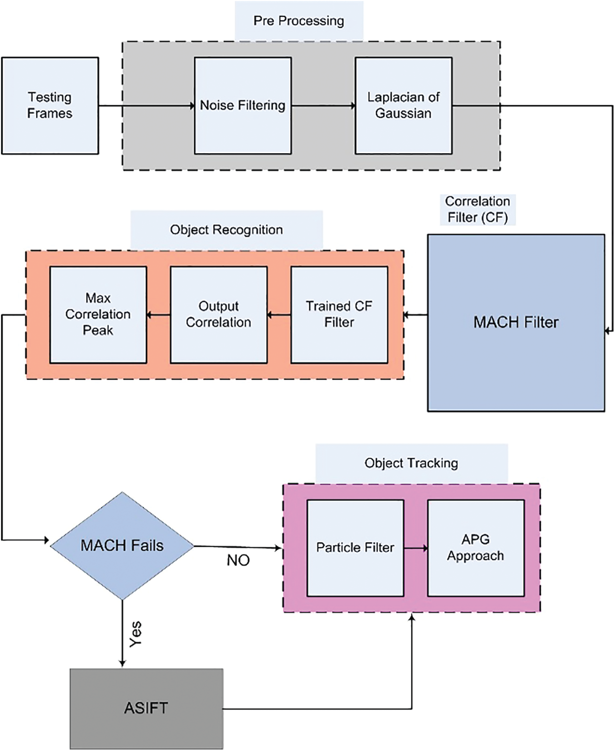
Figure 1: Proposed system model
The working phenomenon of DOG includes smoothing of input image. The smoothing is performed by convolving the Gaussian kernel with the input image. The process is achieved by differentiating two Gaussian functions g(x, y) for σ = 1, 2,…. The Gaussian is expressed using Eq. (1):
Smoothing of input image f(x, y) is performed using Eq. (1) to obtain the output image g1(x, y) as shown in Eq. (2)
Here * represents the convolution. By employing a different width σ2, a second smoothed image is obtained using Eq. (3).
Hence the DOG filtering operation is performed using Eq. (4).
Since the DOG is calculated by differentiating two low pass filters, therefore it can effectively be called a bandpass filter. The DOG eliminates mostly the high frequency components some low-frequency components. After preprocessing, the next step to perform the recognition. The recognition step involves employing of a MACH filter for the object recognition. The first step in using the MACH filter is to train it.
To perform this step, a temporal derivative is computed for each pixel of the input image, which results in a volume for every sequence involved in the training process. Afterwards, in frequency domain, each volume is represented by performing a 2-D Discrete Fourier Transform (DFT) operation using Eq. (5). The output of Eq. (4) i.e., g(x, y) is again considered to be f(x, y) for recursion.
In Eq. (5), the temporal derivative pertaining to each pixel of input sequence is represented by f(x, y). The frequency domain representation of f(x, y) after applying the 2-D DFT is represented by F(u, v). “L” specifies number of columns, “N” specifies number of frames and “M” specifies number of rows. All the resulting columns are then concatenated which were otherwise obtained separately as a result of the 3-D Fourier transform [24,25]. Let xi denote the resulting column of dimension “d” obtained after concatenation. The dimensions are calculated using L * M. After obtaining the column vectors, the MACH filter (which is used for minimization of the ASM, average correlation energy and maximizing a metric called the average correlation height) can be synthesized [26] using Eq. (6).
Here, h shows the frequency response of the filter, mx represents the arithmetic mean of all the input vectors xi, C is d * d dimensional diagonal covariance matrix and d signifies the total number of elements. Dx represents the average spectral density of the training videos and is also a d * d diagonal matrix. Dx is calculated using Eq. (7).
Here * represents the complex conjugate operation. Sx represents the matrix used for average similarity. Sx is calculated using Eq. (8).
where Mx can be considered similar to mx with similar values arranged in a diagonal array. For tradeoff parameters α, β and γ values can be set appropriately [27]. Thus the MACH is implemented using Eq. (9).
In this paper, the MACH parameters have been estimated using Particle Swarm Optimization (PSO) [26]. Tab. 1 shows the estimation of parameters for the data sets being used for testing purposes. The PSO has been employed for the optimization of optimal tradeoff parameters α, β and γ. The chosen parameters for PSO optimization are: Experiments (120), iterations (320), particles (10), dimensions (03), [Xmin, Xmax] = [−1, 1], [Vmin, Vmax] = [−0.1, 0.1], W = 0.9, C1 = C2 = 2. The optimized values of α, β and γ enables much sharper correlation peaks which ensures better object recognition.
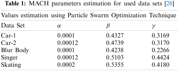
This correlation filter is employed as part of the proposed algorithm for recognition of the object from an image. For training of the filter, a few preliminary frames (eight) for the detection of the object are required. For detection and recognition of the object, i.e., testing of the images, the image is cross correlated with the training images using the two parameters i.e., Peak correlation energy (PCE) and Correlation output peak intensity (COPI). Fig. 2 shows vehicle motion on a circular curve of a road and its correlation peak. The peak shows that the object has been detected effectively.
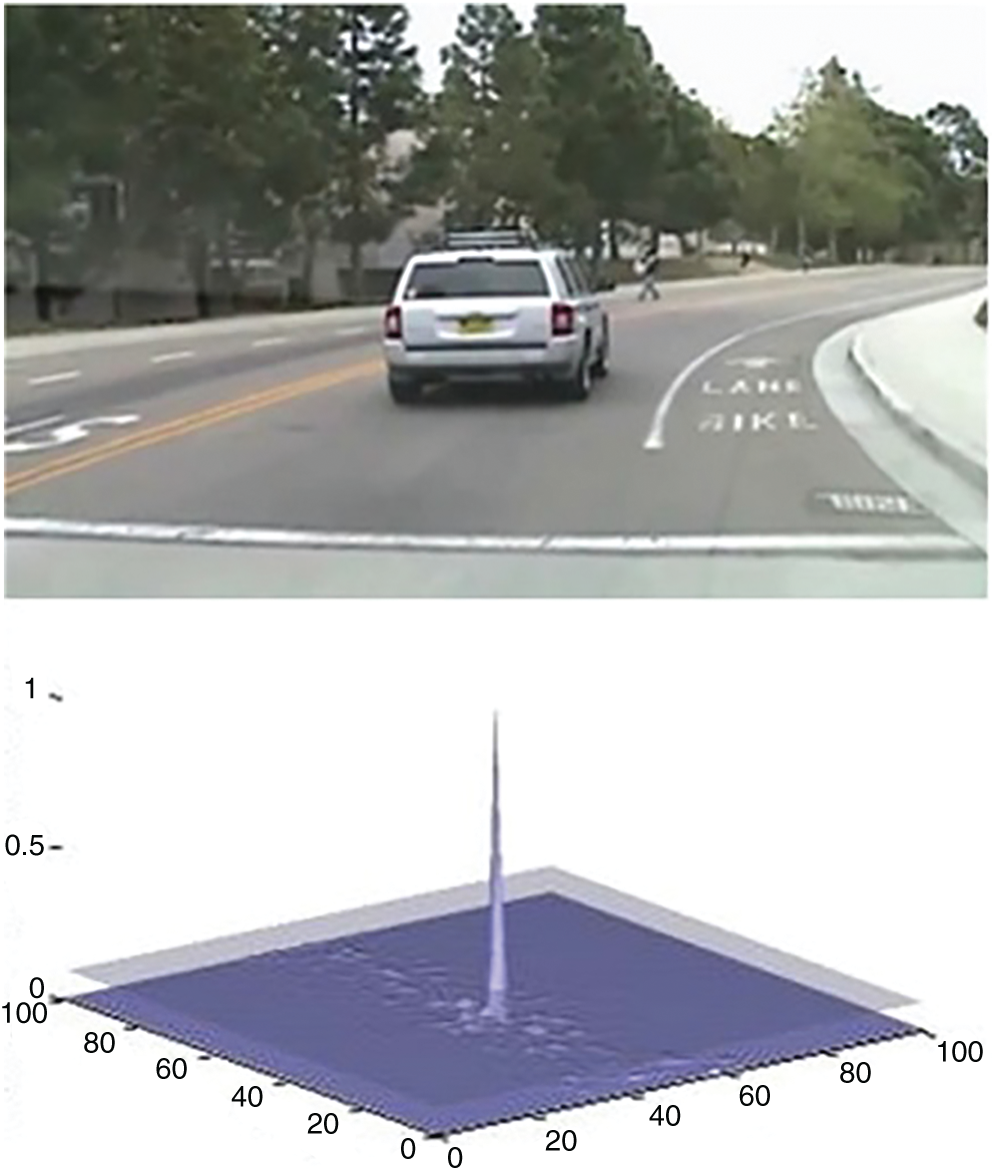
Figure 2: Object detection using MACH with PCE and COPI value are 2.4448e-005 and 34.2351 (Data set: CAR-1)
Fig. 3 shows the correlation peak indicating the presence of object of interest in the image. In this particular instance, the object has undergone a phase shift of 90 degrees. The MACH has once again successfully detected the object using the correlation peak.
Figure 3: Object detection using MACH with PCE and COPI value are 39.7931 and 0.0014 (Data set: CAR-1)
Fig. 4 shows the correlation peak indicating the presence of object of interest in the image. In this particular instance, the object has undergone a scaling factor of 0.84. The MACH has once again successfully detected the object using the correlation peak.
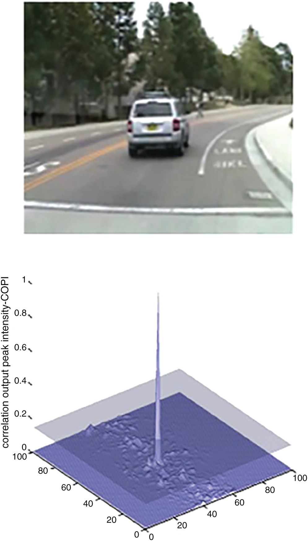
Figure 4: Object detection using MACH with PCE and COPI value are 40.70 and 0.0014 (Data set: CAR-1)
Fig. 5 shows the correlation peak indicating the presence of object of interest in the image. In this particular instance, the object has undergone an occlusion of 30%. The MACH has once again successfully detected the object using the correlation peak.
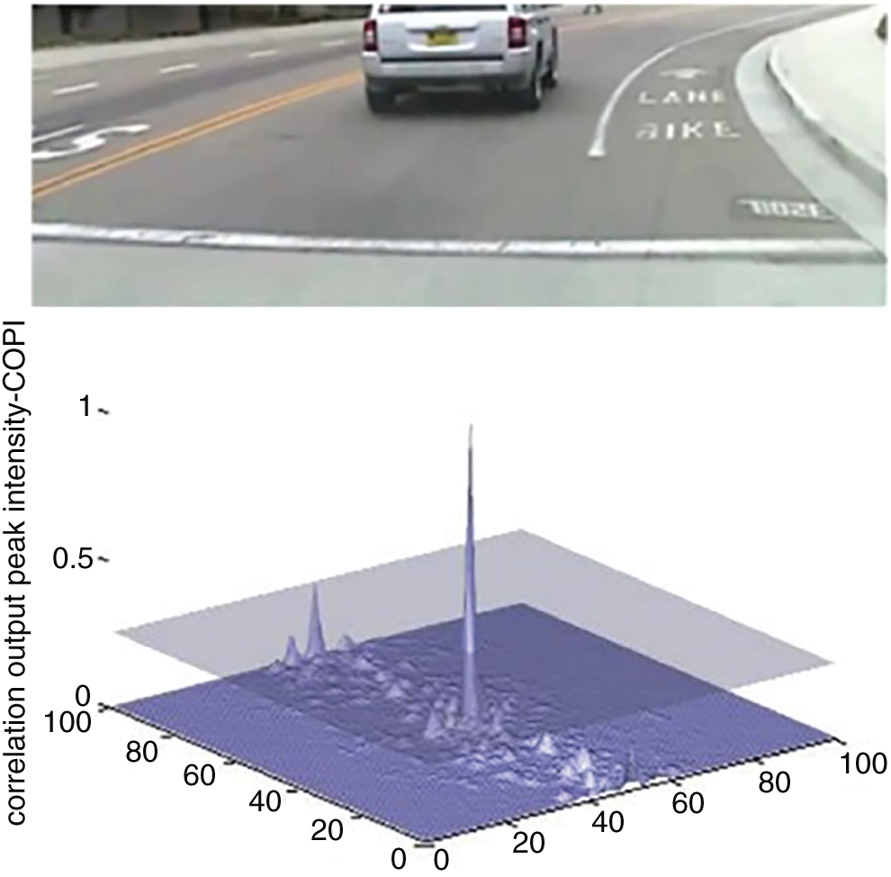
Figure 5: Object detection using MACH with PCE and COPI values are 70.6701 and 0.0025 (Data set: CAR-1)
The peak depicts the identified object coordinates. The coordinates of the object are used to construct the bounding box used for tracking of the object. The bounding box can be seen in Fig. 6.
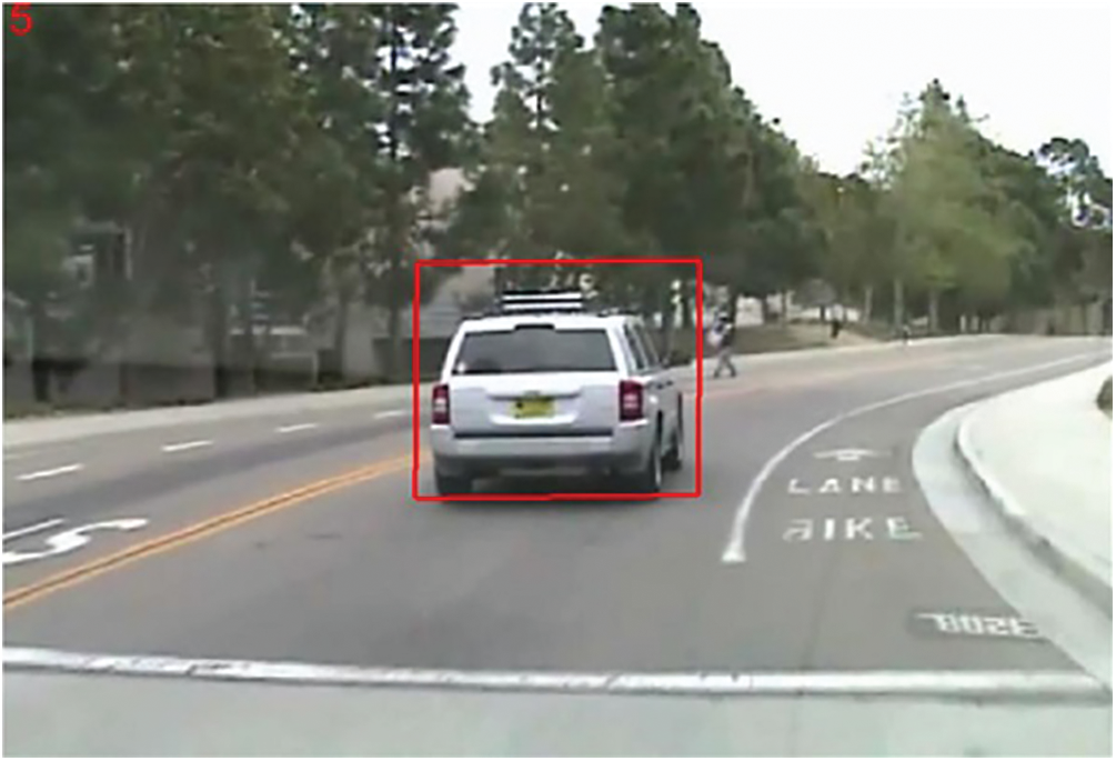
Figure 6: Bounding box around object of interest using MACH filter
Once the bounding box is established, the next task is to track the recognized object once it starts to move. For that, the particle filter-based algorithm will be used. In cases where the object changes its dimensions or path drastically, sometimes the MACH-based recognition filter does not give accurate results. In order to improve the efficiency of the tracker, ensemble of ASIFT and MACH has been proposed. The ensemble has been proposed for the first time, for efficient detection of the object of interest.
In case, object undergoes drastic changes in shift or scale, the MACH tends to give inaccurate results. In addition, in the presence of neighboring objects too close to object of interest, multiple correlation peaks tends to appear. Fig. 7 shows a MACH failure case in which a motion blur causes MACH to fail. To address these concerns, a feature based technique is implemented which covers the limitations of MACH. ASIFT is primarily used in this work because of its ability to detect the presence of the image based on the feature points. In case if object encounters are shift or scale variation, ASIFT is called for better recognition results. An improvement to SIFT was presented by Mehmon [27], which was called ASIFT because of the affine improvement in the SIFT algorithm. ASIFT, in addition to all the invariances provided by the SIFT algorithm, also provided improved accuracy in removing distortions provided by the deviation of the camera axis angle. Then, it applies the SIFT method to the image. Some of the variations, like tilt, are irreversible, i.e., once the tilt of an object is performed, 100% reversal is almost impossible. However, ASIFT performs the tilt in an orthogonal direction to perform the anti-tilt operation. The orthogonal direction tilt has the maximum chance of recovery of the original image. ASIFT uses affine camera model for better estimation of view point changes encountered by the object.
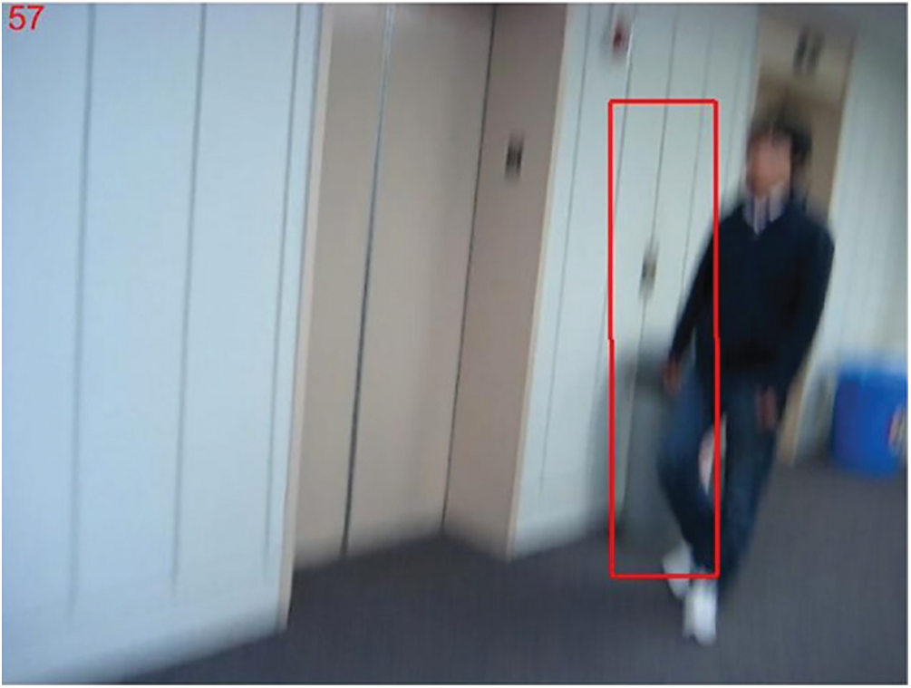
Figure 7: MACH failure case
ASIFT main algorithm: The main algorithm consists of the following steps:
• Each image is transformed using the affine distortion simulations caused by the change in orientation of the camera from frontal positioning. The distortions are dependent mainly on two factors: (i) Latitude θ and longitude Φ. The image must perform Φ rotations, and then, the tilt must be performed with a parameter t = 1/cosθ. For digital images, directional sub-sampling is used for performing the tilt.
• The tilts and rotations are .achieved as required for a finite amount of longitude and latitude angle changes. The sampling steps will most likely ensure that simulated images remain uniform with any other images generated by the same latitude and longitude angles.
• All simulated images are produced by steps 1 and 2. Comparison is then performed using SIFT.
The sampling rate of all the involved parameters to perform tilt is very critical. Object recognition is possible in any slanted case irrespective of the source producing it only if the object is perfectly planar. For this paper, a practical physical upper bound is enforced, i.e., tmax is physically obtained by using image pairs of the object both in the original position and in the slanting position. Multiple examples are presented here. Figs. 8–10 uses data set CAR for demonstration of ASIFT results. After simulations, the feature points are calculated for recognition of the object of interest. Fig. 8a shows the car moving on the road and Fig. 8b shows the same car while it changes the lanes.
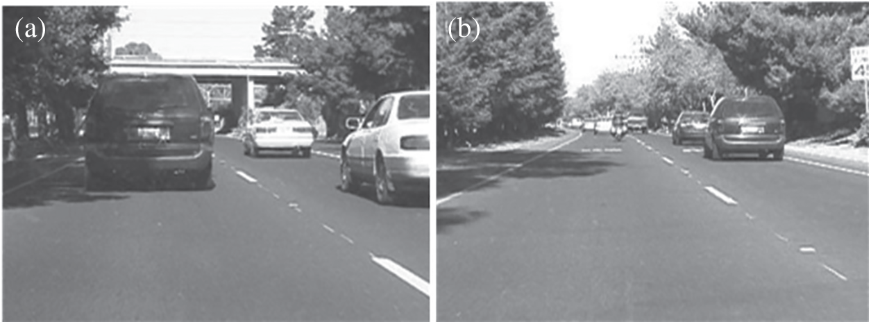
Figure 8: (a) Moving CAR (Frame-1), (b) Moving CAR (Frame-144)
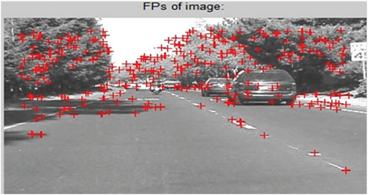
Figure 9: Feature points calculation
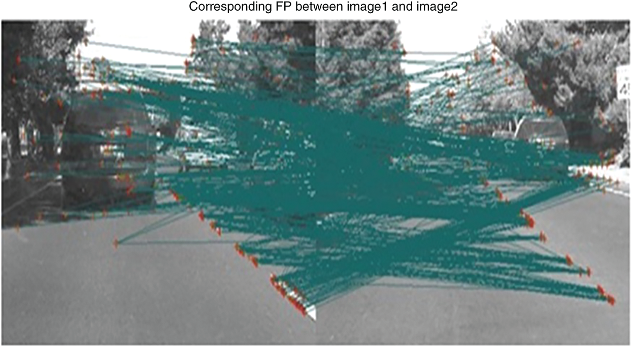
Figure 10: ASIFT matching results (Dataset: CAR-2)
Fig. 9 depicts the calculation of feature points that contribute towards matching via ASIFT. These feature points help in the recognition of the object regardless of any changes in zoom, rotation or change in scale. Fig. 10 shows the ASIFT matching results based on the feature point calculations in both the images. The data set CAR allows very limited scope for testing of the ASIFT algorithm as the vehicle shown in the data set has only shifted lanes but provided no variations in tilt.
Fig. 11 show the ASIFT results on one more data sets that demonstrate that ASIFT uses feature point matches for efficient object recognition. The result verifies the capability of ASIFT in being able to provide better recognition of images in the case of zoom and tilt as compared to MACH.
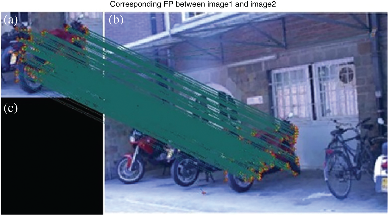
Figure 11: (a) Zoomed image of motor bike, (b) Original scene (c) ASIFT matching results
Fig. 12 shows that the failure case of MACH mentioned in Fig. 7 has been addressed with the help of feature points extracted and matched.
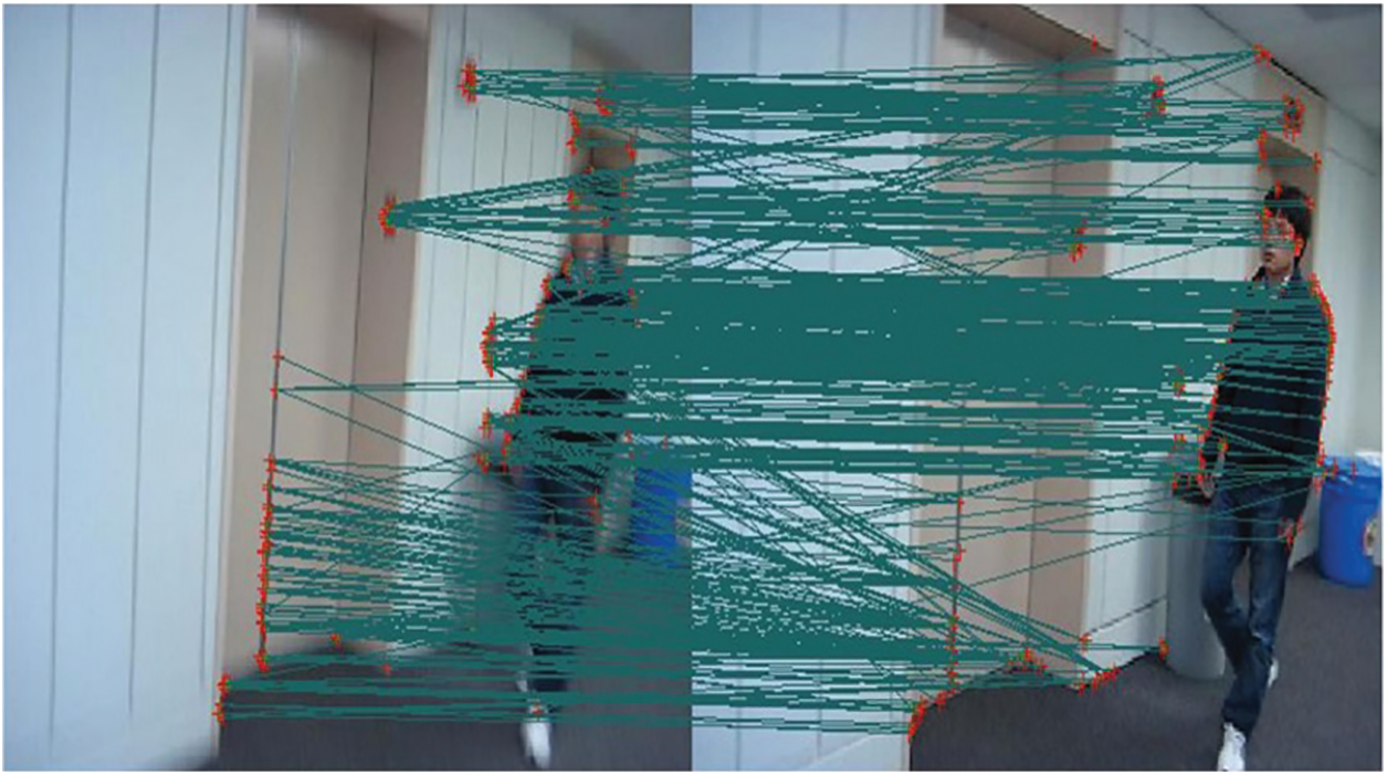
Figure 12: MACH failure case handled through ASIFT
After the recognition of object using MACH or ASIFT, the next step is the efficient tracking of the object in successive frames. The tracking algorithm uses the recognition algorithm in the first frame and then a modified particle filter is employed for updating the positioning of the object in successive frames. The MACH filter is used to construct the bounding box by efficiently performing the object recognition, while the APG based technique is used for updating the coordinates of the bounding box once the object is in motion. ASIFT is called if the longitudinal or latitudinal coordinates of the object change drastically or it starts to tilt as described in the previous section. For object tracking, particle filters are used. The tracking routine that is used in this paper is APG approach which utilizes the particle filter along with the gradient descent technique for object tracking. Algorithm-1 defines the main working principal of the APG approach, summarized below:
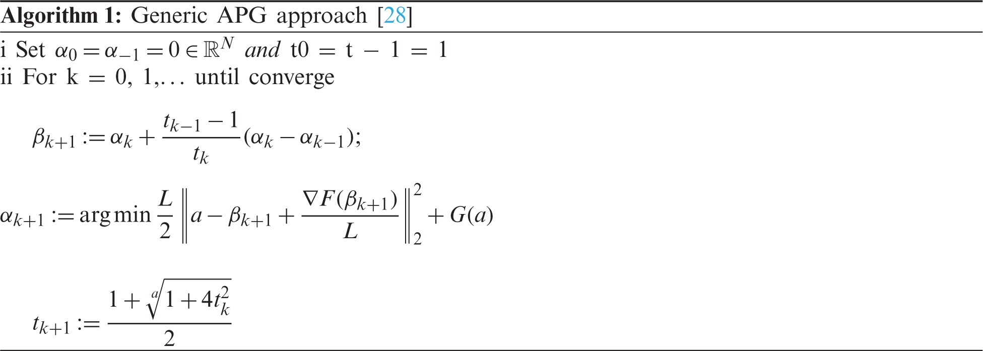
APG based Tracking: Conventionally, APG trackers are generally used for unconstrained minimization problems. So, a typical prerequisite associated with using the APG approach is to first translate a model with constraints into a model with no specific constraints. First, an identity vector is instantiated as an indicator function
The identity function is then applied in the minimization equation of Eq. (11) to get Eq. (12). These equations are used to convert a constrained model to an unconstrained one.
where A′ = [Tt, I] pertains to target templates coefficients. The matrix used for representing non target template coefficients is shown as a = [aT, aI]. For defining the energy pertaining to non-target templates, a crucial parameter, μt, is defined. Now, the APG method is applied on both F(a) and G(a) using Eqs. (13) and (14):
The method uses Eq. (15) for eventual minimization:
The APG-based tracking method is shown in Algorithm-3 that uses the particle filters and the APG approach defined in ALGORITHM. Implementation of the APG-based tracker is performed in MATLAB.
Multiple following datasets are used for the testing of the proposed method. The first dataset involves the Car-1 data set, which shows color images of a vehicle moving around in a curve-like pattern on a road. The data set is obtained from a video sequence that also involves a cluttered scene environment. The algorithm is tested on different frames of the data set, and it can be observed that coordinates of the red bounding box are periodically updated as the object changes its location along a curve. Fig. 13 displays the data set Car-1 and the results are shown accordingly. The second dataset, Car-2, shows a car changing the lanes on the road. The images shown in the data set are grayscale images and, in some frames, the translation and zoom levels of the car change. Fig. 14 shows the implementation of the algorithm on different frames of the data set Car-2. The bounding box is placed after the object detection is performed using the MACH filter. The tracking routine is performed based on APG based tracker.
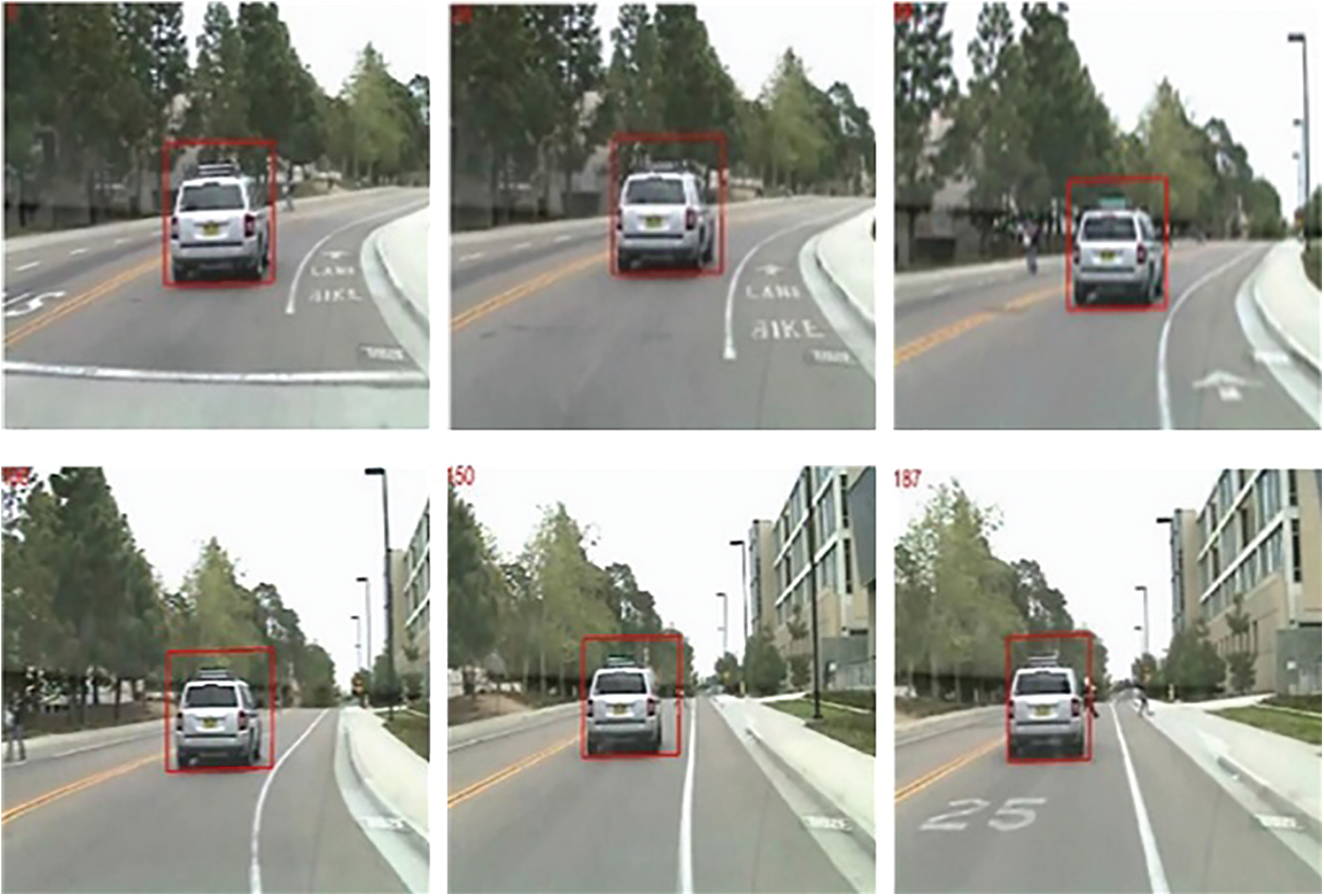
Figure 13: Results of Data Set-1 (CAR-1)
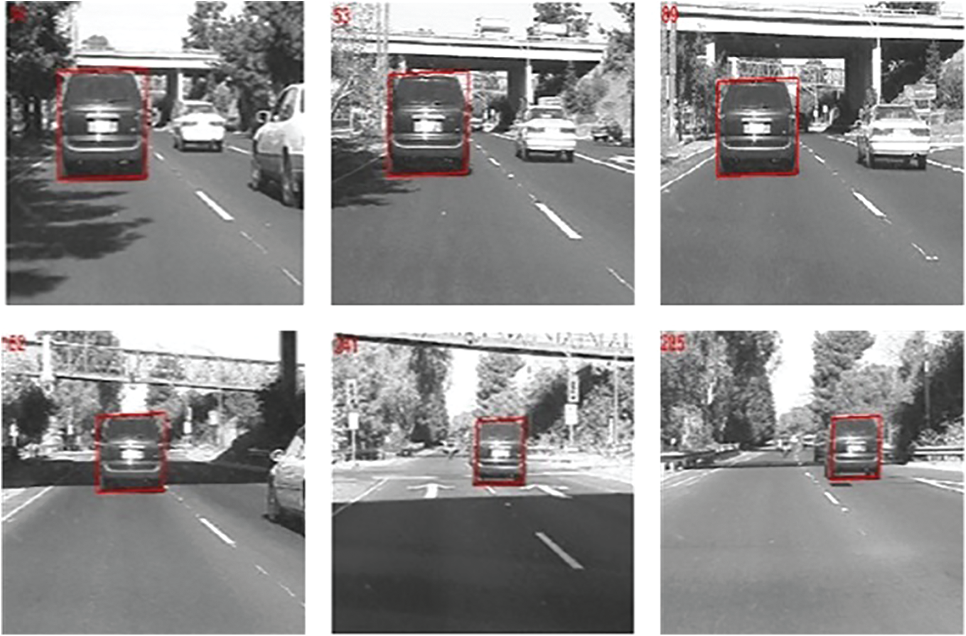
Figure 14: Results of Data Set-2 (CAR-2)
The third dataset shows movement of a person in his office. The dataset is named as “Blur Body” [29]. It shows movement of a person in an office. The data set is interesting considering that multiple images are blurred due to movement of person. The blurred images tests the ability of the tracking algorithm since feature points and correlation peaks are difficult to attain in blurry conditions. Fig. 15 shows the results of BlurBody dataset using APG approach.
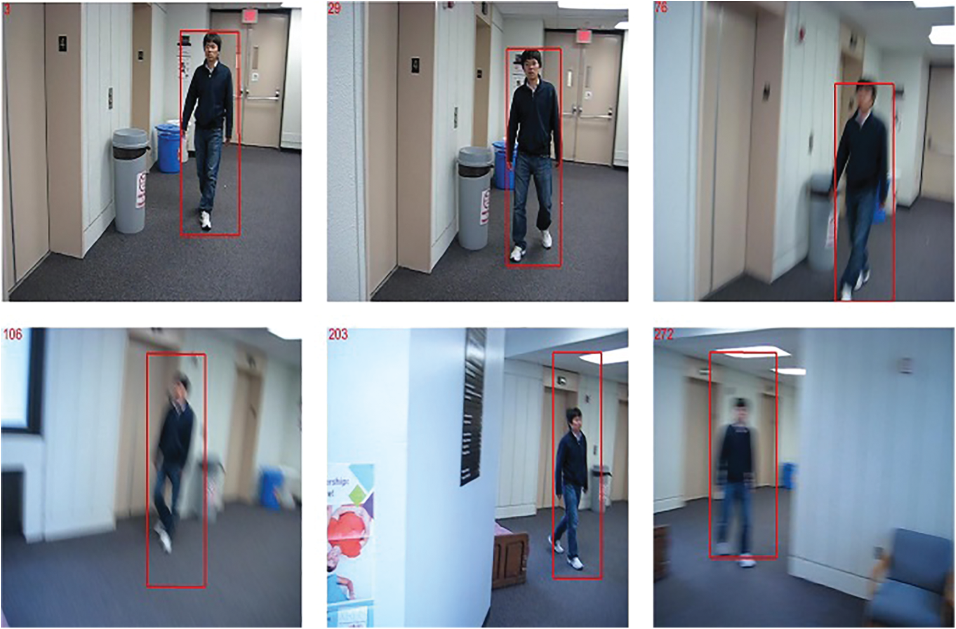
Figure 15: Results of Data Set-3 (Blur Body)
The fourth data employed for testing is referred to as “Singer” [29]. A person is shown singing on stage. The data set pose challenges because multiple images are zoomed in and out as frames starts to increment. The size of the bounding box must constantly be updated for precise results. Fig. 16 shows the results of Singer dataset using APG approach. The fifth data set is referred to as “Skating” [30]. The data set poses challenges because skater gets occluded behind multiple other skaters. The images of the skater also gets zoomed in and out consistently in the data set. Fig. 17 shows the results of Skating dataset using APG approach.
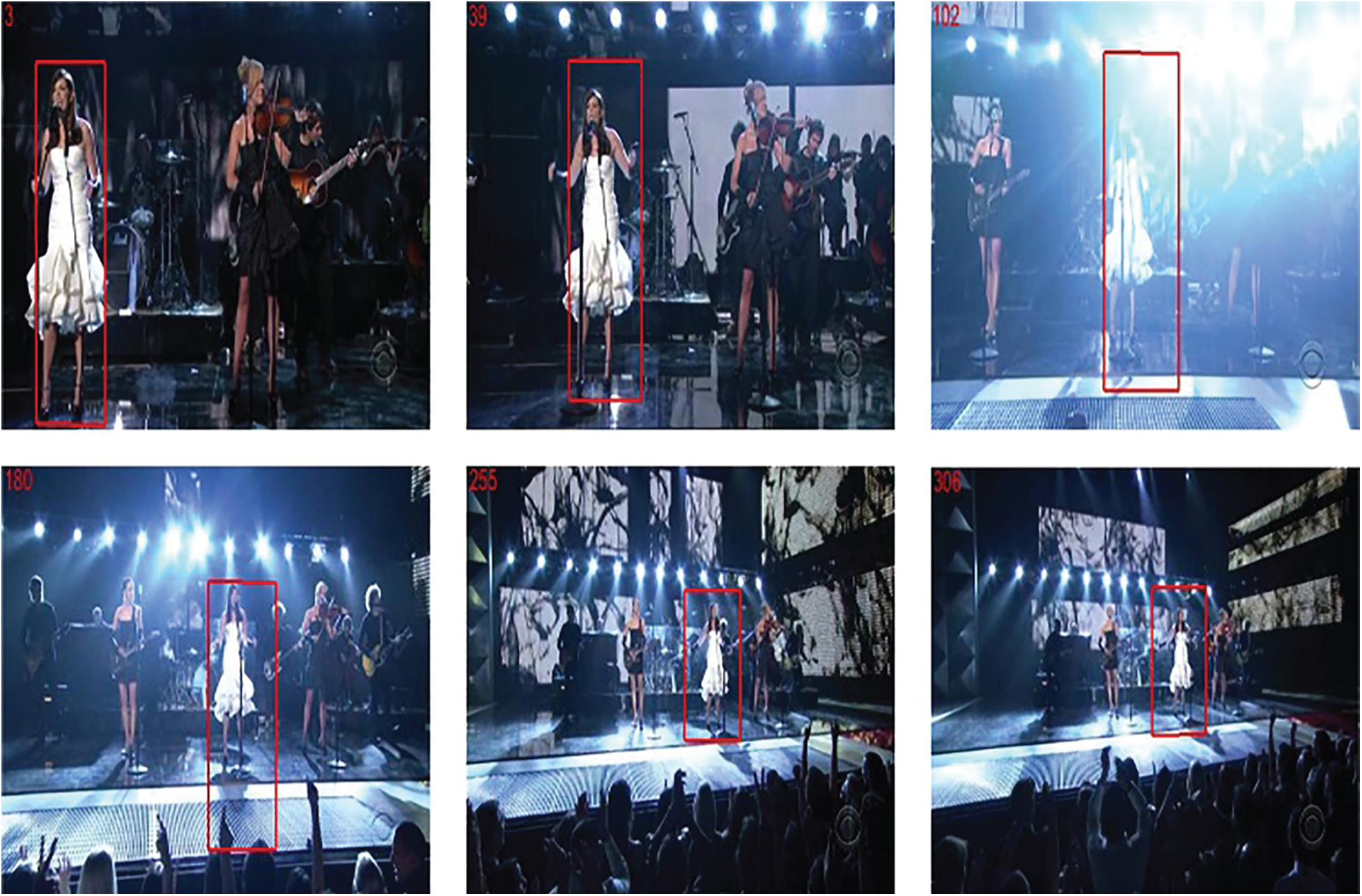
Figure 16: Results of Data Set-4 (Singer)
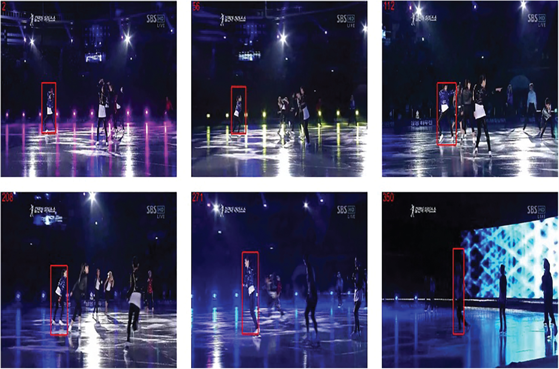
Figure 17: Results of Data Set-5 (Skating)
The results of the data sets shows that the bounding box consistently changes its position in conjunction with the movement of the object. This shows the efficiency and correctness of the tracker and also shows its efficiency while working in an environment with diverse conditions. Data set CAR-1 shows a simple colored object i.e., vehicle moving in a curve like pattern. Data set CAR-2 shows partial occlusion of a vehicle. Data set blur body shows occasional blurring of an object. Data set skating and singer each shows changes in projection and lightening conditions occasionally.
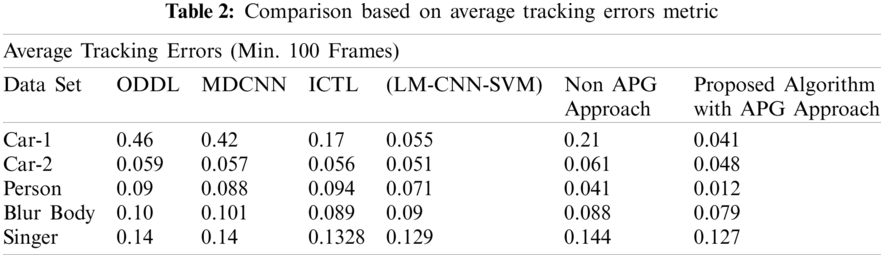
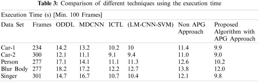
The proposed algorithm is compared with similar state of the art algorithms in terms of execution time and average tracking errors. The average tracking error is measured using the Euclidian distance of two center points, which has been normalized by the size of the target from the ground truth. The execution time is based on how fast the algorithm can detect the object of interest precisely. The execution time of algorithms is calculated using same language and machine i.e., MATLAB 2019 and Core i5 processing machine. The algorithm is compared to some of the state-of-the-art algorithms such as novel hybrid Local Multiple system (LM-CNN-SVM) based on Convolutional Neural Networks (CNNs) and Support Vector Machines (SVMs) [30], Object Detection with Deep Learning (ODDL) [31], Multi-scaled and deformable convolutional neural networks (MDCNN) [32] and Incremental Covariance Tensor Learning (ICTL) [33]. Detailed results are shown using both the non-APG and the APG approach. The results depict that the APG based implementation clearly shows better performance as compared to all the existing approaches. Tabs. 2 and 3 shows the comparison results based on average tracking errors and Euclidean distance respectively. Tabs. 2 and 3 clearly depict that the merger of MACH filter with the APG-based filter gives more accurate results as compared to the existing algorithms. Tab. 2 depicts the average tracking errors encountered by the proposed tracking algorithm in comparison with other similar state of the art algorithms. The proposed APG based algorithm shows better precision as compared to the other algorithms. Tab. 3 also shows execution time for the proposed APG based algorithm, thus depicting better run time speed as compared with other algorithms. For further improvement in the proposed algorithms, PSO based deep learning methods can also be opted [34,35]
This paper proposes an efficient technique that utilizes an ensemble of two recognition techniques and a novel tracking routine for tracking of fixed shape moving objects. First, MACH is used for detecting the object of interest by maximizing the average similarity measure. The detected coordinates are used to construct a bounding box that indicates the presence of object. In each subsequent frame, the coordinates of the bounding box are updated using the APG approach. The analysis show that the proposed algorithm is not only less error prone compared to the previous methods, but it also possesses less computational complexity than its predecessors due to the APG approach. The APG method eradicates the practice of templates that are trivial in nature, resulting in fewer complexities and a faster tracking procedure. The proposed algorithm can be improved in the future by training the proposed tracker to work on objects that have been occluded in a remote scene environment. Once the object becomes occluded, the MACH filter will be used for the prediction of coordinates instead of the particle filter, to hopefully provide more accurate results.
Funding Statement: This research was supported by X-mind Corps program of National Research Foundation of Korea (NRF) funded by the Ministry of Science, ICT (No. 2019H1D8A1105622) and the Soonchunhyang University Research Fund.
Conflicts of Interest: The authors declare that they have no conflicts of interest to report regarding the present study.
1. T. Mahalingam and M. Subramoniam, “A robust single and multiple moving object detection, tracking and classification,” Applied Computing and Informatics, vol. 2, no. 1, pp. 1–21, 2020. [Google Scholar]
2. M. Rashid, M. Alhaisoni, S. H. Wang, S. R. Naqvi, A. Rehman et al., “A sustainable deep learning framework for object recognition using multi-layers deep features fusion and selection,” Sustainability, vol. 12, no. 12, pp. 5037, 2020. [Google Scholar]
3. N. Hussain, M. Sharif, S. A. Khan, A. A. Albesher, T. Saba et al., “A deep neural network and classical features based scheme for objects recognition: An application for machine inspection,” Multimedia Tools and Applications, vol. 1, no. 2020, pp. 1–23, 2020. [Google Scholar]
4. M. Rashid, M. Raza, M. M. Sarfraz and F. Afza, “Object detection and classification: A joint selection and fusion strategy of deep convolutional neural network and SIFT point features,” Multimedia Tools and Applications, vol. 78, no. 2019, pp. 15751–15777, 2019. [Google Scholar]
5. H. Braun, S. Katoch, P. Turaga, A. Spanias and C. Tepedelenlioglu, “A MACH filter-based reconstruction-free target detector and tracker for compressive sensing cameras,” International Journal of Smart Security Technologies, vol. 7, no. 2, pp. 1–21, 2020. [Google Scholar]
6. H. Masood, S. Rehman, M. Khan, Q. Javed, M. Abbas et al., “A novel technique for recognition and tracking of moving objects based on E-MACH and proximate gradient filters,” in 2017 20th Int. Conf. of Computer and Information Technology, Dhaka, Bangaldesh, pp. 1–6, 2017. [Google Scholar]
7. R. Polana and R. Nelson, “Low level recognition of human motion (or how to get your man without finding his body parts),” in Proc. of 1994 IEEE Workshop on Motion of Non-Rigid and Articulated Objects, Austin, TX, USA, pp. 77–82, 1994. [Google Scholar]
8. I. A. Essa and A. P. Pentland, “Coding, analysis, interpretation, and recognition of facial expressions,” IEEE Transactions on Pattern Analysis and Machine Intelligence, vol. 19, no. 7, pp. 757–763, 1997. [Google Scholar]
9. K. Mikolajczyk and C. Schmid, “Scale & affine invariant interest point detectors,” International Journal of Computer Vision, vol. 60, no. 1, pp. 63–86, 2004. [Google Scholar]
10. L. Zhang, J. Xia, X. Ying, Y. He and H. S. Seah, “Efficient and robust 3D line drawings using difference-of-Gaussian,” Graphical Models, vol. 74, no. 4, pp. 87–98, 2012. [Google Scholar]
11. J. M. Morel and G. Yu, “ASIFT: A new framework for fully affine invariant image comparison,” SIAM Journal on Imaging Sciences, vol. 2, no. 2, pp. 438–469, 2009. [Google Scholar]
12. D. G. Lowe, “Distinctive image features from scale-invariant keypoints,” International Journal of Computer Vision, vol. 60, no. 2, pp. 91–110, 2004. [Google Scholar]
13. Y. Ke and R. Sukthankar, “PCA-Sift: A more distinctive representation for local image descriptors,” in Proc. of the 2004 IEEE Computer Society Conf. on Computer Vision and Pattern Recognition, NY, USA, pp. 1–6, 2004. [Google Scholar]
14. K. Mikolajczyk and C. Schmid, “A performance evaluation of local descriptors, IEEE Transcations on Pattern Analysis and Machine Intelligence, vol. 27, no. 10, pp. 1615–1630, 2005. [Google Scholar]
15. M. El-Khoreby, S. Abu-Bakar, M. M. Mokji and S. Omar, “Vehicle detection and counting using adaptive background model based on approximate median filter and triangulation threshold techniques,” Automatic Control and Computer Sciences, vol. 54, no. 4, pp. 346–357, 2020. [Google Scholar]
16. M. Sharif, T. Akram, M. Y. Javed, T. Saba and A. Rehman, “A framework of human detection and action recognition based on uniform segmentation and combination of Euclidean distance and joint entropy-based features selection,” EURASIP Journal on Image and Video Processing, vol. 2017, no. 1, pp. 1–18, 2017. [Google Scholar]
17. M. Zahid, F. Azam, S. Kadry and J. R. Mohanty, “Pedestrian identification using motion-controlled deep neural network in real-time visual surveillance,” Soft Computing, vol. 11, pp. 1–17, 2021. [Google Scholar]
18. I. M. Nasir, M. Yasmin, J. H. Shah, M. Gabryel, R. Scherer et al., “Pearson correlation-based feature selection for document classification using balanced training,” Sensors, vol. 20, no. 23, pp. 6793, 2020. [Google Scholar]
19. M. S. Sarfraz, M. Alhaisoni, A. A. Albesher, S. Wang and I. Ashraf, “Stomachnet: Optimal deep learning features fusion for stomach abnormalities classification,” IEEE Access, vol. 8, no. 20, pp. 197969–197981, 2020. [Google Scholar]
20. K. Aurangzeb, I. Haider, T. Saba, K. Javed, T. Iqbal et al., “Human behavior analysis based on multi-types features fusion and von nauman entropy based features reduction,” Journal of Medical Imaging and Health Informatics, vol. 9, no. 4, pp. 662–669, 2019. [Google Scholar]
21. Y. D. Zhang, S. A. Khan, M. Attique, A. Rehman and S. Seo, “A resource conscious human action recognition framework using 26-layered deep convolutional neural network,” Multimedia Tools and Applications, vol. 2, no. 21, pp. 1–23, 2020. [Google Scholar]
22. K. Javed, S. A. Khan, T. Saba, U. Habib, J. A. Khan et al., “Human action recognition using fusion of multiview and deep features: An application to video surveillance,” Multimedia Tools and Applications, vol. 1, no. 20, pp. 1–27, 2020. [Google Scholar]
23. M. Sharif, T. Akram, M. Raza, T. Saba and A. Rehman, “Hand-crafted and deep convolutional neural network features fusion and selection strategy: An application to intelligent human action recognition,” Applied Soft Computing, vol. 87, pp. 105986, 2020. [Google Scholar]
24. S. Rehman, R. Young, P. Birch, C. Chatwin and I. Kypraios, “Fully scale and in-plane invariant synthetic discriminant function bandpass difference of Gaussian composite filter for object recognition and detection in still images,” Journal of Theoretical and Applied Information Technology, vol. 5, no. 2, pp. 232–241, 2005. [Google Scholar]
25. J. Fan, X. Shen and Y. Wu, “What are we tracking: A unified approach of tracking and recognition,” IEEE Transactions on Image Processing, vol. 22, no. 2, pp. 549–560, 2012. [Google Scholar]
26. S. Tehsin, S. Rehman, M. O. B. Saeed, F. Riaz, A. Hassan et al., “Self-organizing hierarchical particle swarm optimization of correlation filters for object recognition,” IEEE Access, vol. 5, no. 17, pp. 24495–24502, 2017. [Google Scholar]
27. M. H. Memon, J. P. Li, I. Memon and Q. A. Arain, “GEO matching regions: Multiple regions of interests using content based image retrieval based on relative locations,” Multimedia Tools and Applications, vol. 76, no. 14, pp. 15377–15411, 2017. [Google Scholar]
28. C. Bao, Y. Wu, H. Ling and H. Ji, “Real time robust l1 tracker using accelerated proximal gradient approach,” in 2012 IEEE Conf. on Computer Vision and Pattern Recognition, NY, USA, pp. 1830–1837, 2012. [Google Scholar]
29. Y. Wu, H. Ling, J. Yu, F. Li and E. Cheng, “Blurred target tracking by blur-driven tracker,” in 2011 Int. Conf. on Computer Vision, NY, USA, pp. 1100–1107, 2011. [Google Scholar]
30. J. Kwon and K. M. Lee, “Visual tracking decomposition,” in 2010 IEEE Computer Society Conf. on Computer Vision and Pattern Recognition, Las Vegas, pp. 1269–1276, 2010. [Google Scholar]
31. A. Uçar, Y. Demir and C. Güzeliş, “Object recognition and detection with deep learning for autonomous driving applications,” Simulation, vol. 93, no. 9, pp. 759–769, 2017. [Google Scholar]
32. D. Cao, Z. Chen and L. Gao, “An improved object detection algorithm based on multi-scaled and deformable convolutional neural networks,” Human-Centric Computing and Information Sciences, vol. 10, no. 10, pp. 1–22, 2020. [Google Scholar]
33. F. Porikli, O. Tuzel and P. Meer, “Covariance tracking using model update based on means on riemannian manifolds,” in Proc. IEEE Conf. on Computer Vision and Pattern Recognition, NY, USA, pp. 728–735, 2006. [Google Scholar]
34.R. A. Naqvi, M. Arsalan, A. Rehman and A. U. Rehman, “A. deep learning-based drivers emotion classification system in time series data for remote applications,” Remote Sensing, vol. 12, no. 3, pp. e587, 2020. [Google Scholar]
35. K. Aurangzeb, S. Aslam, M. Alhussein, R. A. Naqvi and M. Arsalan, “Contrast enhancement of fundus images by employing modified PSO for improving the performance of deep learning models,” IEEE Access, vol. 9, no. 21, pp. 47930–47945, 2021. [Google Scholar]
 | This work is licensed under a Creative Commons Attribution 4.0 International License, which permits unrestricted use, distribution, and reproduction in any medium, provided the original work is properly cited. |