DOI:10.32604/cmc.2022.017105
| Computers, Materials & Continua DOI:10.32604/cmc.2022.017105 | |
| Article |
Resource Allocation for Throughput Maximization in Cognitive Radio Network with NOMA
1School of Computer Science, Sichuan University of Science and Engineering, Zigong, 643000, China
2Department of Network Information Management Center, Sichuan University of Science and Engineering, Zigong, 643000, China
3School of Information Engineering, South West University of Science and Technology, Mianyang, 621010, China
4School of Computer and Software, Nanjing University of Information Science and Technology, Jiangsu, 210044, China
5Alhamd Islamic University Airport Road Quetta, Balochistan, Pakistan
*Corresponding Author: Yu Song. Email: songyu_suse@hotmail.com
Received: 18 January 2021; Accepted: 21 February 2021
Abstract: Spectrum resources are the precious and limited natural resources. In order to improve the utilization of spectrum resources and maximize the network throughput, this paper studies the resource allocation of the downlink cognitive radio network with non-orthogonal multiple access (CRN-NOMA). NOMA, as the key technology of the fifth-generation communication (5G), can effectively increase the capacity of 5G networks. The optimization problem proposed in this paper aims to maximize the number of secondary users (SUs) accessing the system and the total throughput in the CRN-NOMA. Under the constraints of total power, minimum rate, interference and SINR, CRN-NOMA throughput is maximized by allocating optimal transmission power. First, for the situation of multiple sub-users, an adaptive optimization method is proposed to reduce the complexity of the optimization solution. Secondly, for the optimization problem of nonlinear programming, a maximization throughput optimization algorithm based on Chebyshev and convex (MTCC) for CRN-NOMA is proposed, which converts multi-objective optimization problem into single-objective optimization problem to solve. At the same time, the convergence and time complexity of the algorithm are verified. Theoretical analysis and simulation results show that the algorithm can effectively improve the system throughput. In terms of interference and throughput, the performance of the sub-optimal solution is better than that of orthogonal-frequency-division-multiple-access (OFDMA). This paper provides important insights for the research and application of NOMA in future communications.
Keywords: Resource allocation; non-orthogonal multiple access; cognitive radio network; throughput maximization; Chebyshev; convex
The secondary users (SUs) of the cognitive radio network (CRN) can have an opportunity to access the licensed spectrum of the primary user (PU). Therefore, spectrum utilization can be improved by sharing spectrum between SUs and PU. At present, the researches about CRN mainly focus on the network resources allocation. However, the flexibility of radio spectrum access brings new challenges to CRN.
How to use the limited spectrum resources to provide higher transmission rates for more users has always been a focus and research issue in the wireless communication field. With the fifth-generation mobile communication network (5G) technology becoming more and more attractive, 5G has been widely used in a large number of applications [1]. Non-orthogonal multiple access (NOMA) technology as a key technology for 5G has also received widespread attention in the industry. Compared with orthogonal multiple access (OMA), NOMA can allocate an orthogonal resource to multiple users by introducing new dimensions such as power domain, thereby improving the spectrum efficiency of the system [2].
CRN based on NOMA technology is called CRN-NOMA. When more SUs access the CRN-NOMA, the spectrum efficiency and total throughput of the system can be effectively improved. In view of the power domain multiplexing characteristics of NOMA, the SUs of CRN-NOMA multiplex the sub-channel of the PU in the manner of NOMA. On the one hand, the transmitter performs power allocation according to the channel gains of different SUs. On the other hand, the receiver uses successive interference cancellation (SIC) technology to correctly demodulate through different power values in order to distinguish the target signal from the interference signal [3]. Obviously, a reasonable power allocation scheme is particularly important. However, traditional power allocation methods (e.g., full search algorithm, fixed power allocation algorithm and fractional order power allocation algorithm) are not suitable for CRN-NOMA. Therefore, how to design an effective and low complexity power allocation algorithm to further improve the network throughput has become a hotspot in academic research.
At present, there are many research works related to NOMA in wireless transmission. It can be seen from these research studies that SIC and power multiplexing are the key technologies of NOMA. Among them, power multiplexing technology is a research hotspot of scholars. Unlike ordinary power control, the NOMA power multiplexing technology is used by the base station (BS) to perform power allocation through related algorithms, and to achieve certain performance with limited resources.
Wang et al. [4] investigated the power allocation of the downlink NOMA system, which consisted of a BS and two users. Choi [5] presented the power control of the downlink NOMA proportional fair scheduling (PFS) with two users. Through different standards, the PFS scheme that maximized the minimum normalized rate was used to find the best power allocation scheme. In addition to considering the downlink NOMA system, Yang et al. [6] also proposed a dynamic power allocation scheme (D-NOMA) for the uplink NOMA scheme with two users. This scheme had given analytical expressions for outage probability and average rate. D-NOMA can obtain the same diversity gain as F-NOMA, avoiding the situation where the rate of users with poor channel conditions was less than OMA. The above three references are all proposed power allocation schemes for two users NOMA scenarios, but this scheme may fail if there are multiple users. Aiming at the problem of the number of users, Chen et al. [7] proposed to use the advantages of multi-antenna base stations to support large-scale access through user clustering in the spatial domain.
In view of the shortcomings of fixed transmit power, researchers have initiated studies on CRN-NOMA [8–10]. Since there are multiple PUs and SUs in the CRN, in order to improve the spectrum utilization, it is recommended to study the NOMA communication scenarios of multiple users. In these studies, scholars have carried out researches around single CRN-NOMA and relay CRN-NOMA. Wu et al. [8] studied the power allocation problem of CRN-NOMA downlink. The optimization goal was to maximize the number of SUs accessing the system and improve the spectrum efficiency of the system. Tsiropoulos et al. [9] proposed a new power allocation algorithm using the characteristics of the NOMA system. Through the setting of the total power of SUs, the QoS requirements of PUs were guaranteed. Alhamad et al. [10] derived the throughput of NOMA with adaptive transmit power in CRN-NOMA. In order to maximize the throughput of CRN-NOMA, the power allocated to near and far users was optimized [10].
In order to expand the transmission distance, some scholars have studied the relay CRN-NOMA. Chu et al. [11] proposed and studied a CRN-NOMA cooperative relay scheme. Wu et al. [12] proposed an optimal power allocation problem for base stations and relays to maximize the total throughput of transmission to MU. In addition, the outage probability is another important part of CRN-NOMA research. When the link capacity cannot meet the required SUs rate, an interrupt event will occur. The authors of [13] considered the performance of the network and proposed a new closed-form expression of the outage probability using the random geometric method. Through the diversity analysis, new insights were obtained in the two situations with different power constraints.
Form the previous analysis, it can be seen that the current research works of CRN-NOMA mainly focus on the outage probability, traversal capacity, user fairness and resource allocation. The communication scenarios of tow SUs are mainly studied. However, with the increasing complexity of the network structure, the optimization of multi-user CRN-NOMA throughput is also an interesting research direction. This paper investigates the optimization problem in the multi-user CRN-NOMA scenario, namely the number of SUs accessing the system and the total system throughput. Under multiple constraints, CRN-NOMA throughput is improved by allocating optimal transmission power of SUs.
This paper mainly studies the problem of CRN-NOMA power allocation optimization, i.e., SUs accessing number and throughput optimization. The main contributions of this paper are as follows:
• First, at the transmitting end, power allocation is performed according to the channel conditions of the SUs. In order to meet the communication requirements of multi-user scenarios, the superimposed coding technology is used to send signals to multiple SUs at the same time. The transmitter ensures user performance by adjusting the power distribution coefficient.
• Secondly, different SUs have different signal strengths at the receiving end. In accordance with the order of signal strength, SIC technology is used for signal demodulation. Signals with high strength are demodulated first, and this signal component is subtracted. Then the weak signals are demodulated in turn, and finally the useful signal is recovered.
• Then, in order to avoid the high complexity of the algorithm, an adaptive search algorithm is used to solve the maximum number of connected SUs.
• Finally, Chebyshev is used to transform the multi-objective optimization problem into single-objective optimization problem. A maximization throughput algorithm based on Chebyshev and convex optimization (MTCC) is proposed, which has the characteristics of low complexity and fast convergence.
The remainder of this paper is organized as follows. The network and system model are introduced in Section 2. In Section 3, the power allocation study for maximum SUs access number and throughput in a CRN-NOMA scenario is formulated. Based on Chebyshev and convex optimization (MTCC) are designed in Section 4. Numerical and simulation results are presented in Section 5. Finally, Section 6 concludes this paper.
As shown in Fig. 1, we consider a downlink underlay CRN communication scenario composed of a primary network and a secondary network. The primary network is composed of a primary base station (PBS) and a PU, while the secondary network is composed of a secondary base station (SBS) with NOMA function and N SUs. PBS provides communication for PU and SBS. SUs are randomly distributed in a two-dimensional plane and obeyed Poisson distribution. The transmit power of PBS is PPBS. In the downlink, SBS allocates more power to users with poor channel conditions and less power to users with good channel conditions according to the NOMA principle. We also assume that the downlink channel bandwidth is denoted as W, which equals to 1 Hz. In the communication scenario of this paper, it is assumed that the SBS establishes a direct connection with N SUs, and sends the superimposed modulated signal (SMS) to the N SUs at the same time.
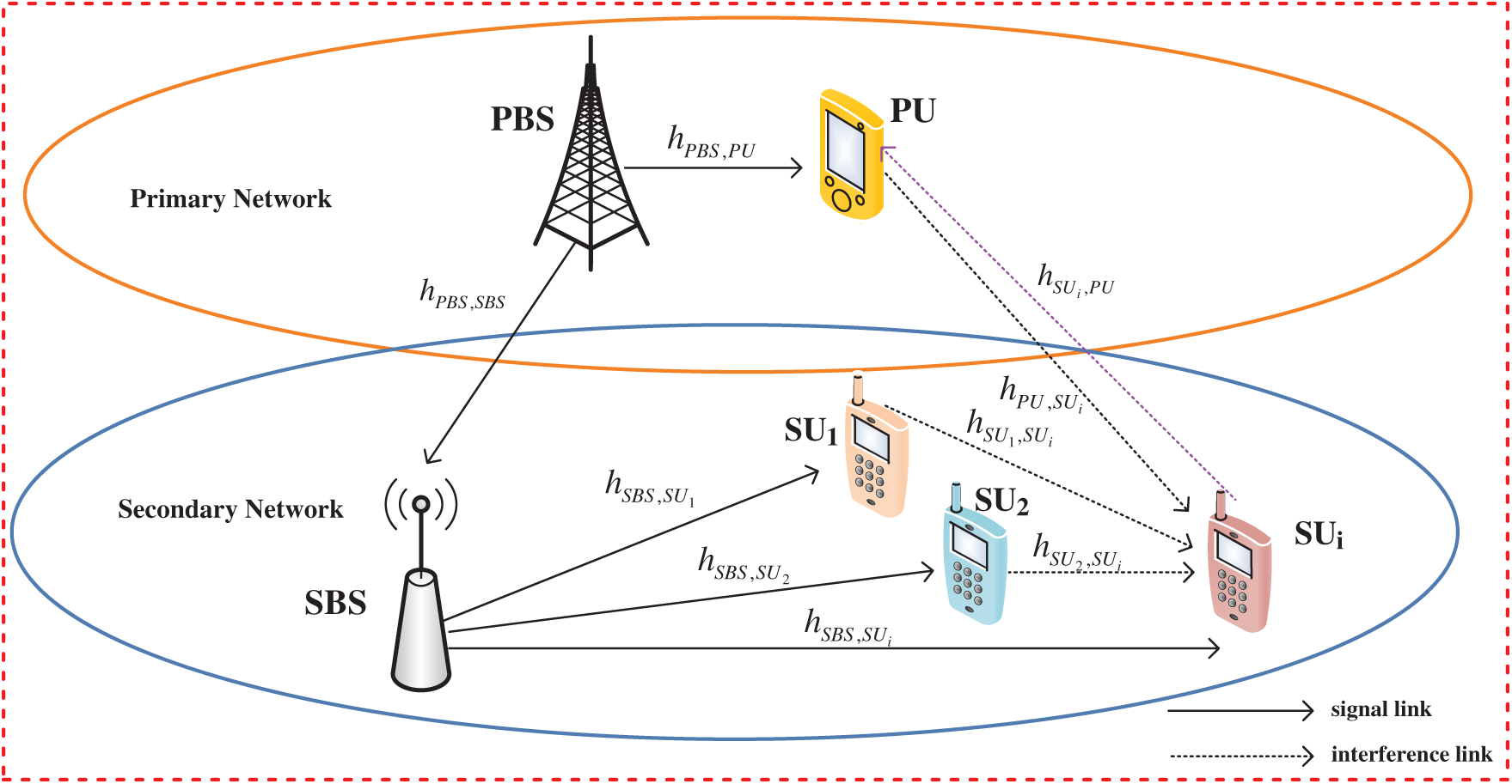
Figure 1: System model
We use SUi
Since CRN-NOMA adopts the underlay spectrum sharing model, the access SUi will be interfered by the PU and other SUs in the same frequency band. In order to reduce the interference to SUi, the SCI technology in NOMA can be used to eliminate the signal interference between SUs until the desired signal is decoded. As shown in Fig. 2, the SBS simultaneously transmits signals for N SUs with different distances on the same frequency band. Generally, the SBS allocates transmission power PSUi for signal xSBS, SUi of remote user (SUi) higher than its allocated transmission power PSUi −1 for signal xSBS, SUi −1 of near user (SUi −1).
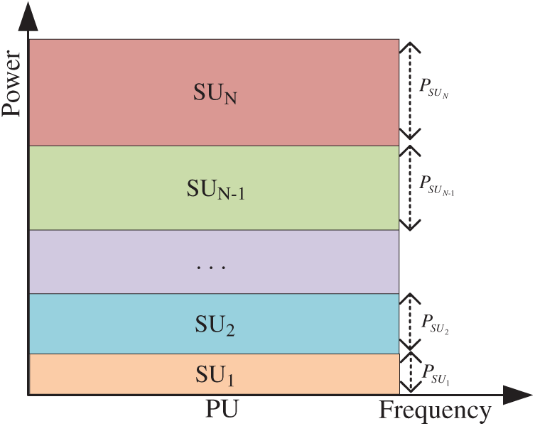
Figure 2: NOMA model of power allocation
We assume that the channel gains of the communication links of the SUs are sorted in descending order, and then the signal power of these SUs is arranged in ascending order. The specific assumption is as follows, the order of channel gain from SBS to its i-th receiver SUi is
Each level of the SIC detector only detects one signal, so N users need N levels of decision. In the multi-stage structure, the output signal of the previous stage is used as the input signal of the next stage. The specific process is shown in Fig. 3. Before the first level of detection, the received signals are sorted according to the signal power. Since xSBS, SUN is the strongest, xSBS, SUN is judged first, and xSBS, SUN is output. Then the signal estimation of xSBS, SUN is restored, and xSBS, SUN is subtracted from the received signal. The estimated value is
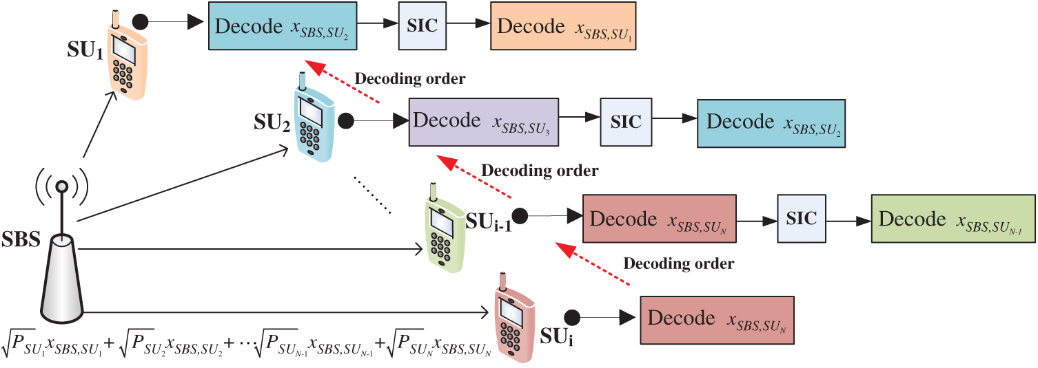
Figure 3: NOMA model of decoding process
The NOMA system model is shown in Fig. 1. It can be seen from Fig. 1 that there are a total of N SUs in the same frequency domain, time and space resource blocks using SCI technology for transmission. According to the previous system assumptions, the received signal at PBS, which is denoted as yPU, can be written as follows:
where PPBS is the transmission power of PBS, the xPBS, PU is the transmission data signal of PBS. nPBS, PU is additive white Gaussian noise with mean value of zero and variance of
We can write the received signal at SBS as follows:
where xPBS, SBS is the transmission data signal of PBS to SBS. nPBS, SBS is additive white Gaussian noise with mean value of zero and variance of
The SBS broadcasts the NOMA signal to SUi (
where PSBS is the transmission power of SBS.
We can substitute the Eq. (3) into the Eq. (4) to get the Eq. (5), and its specific expression is as follows:
where PSBS, PPU, PSUj are the transmission power of SBS, PU and SUj (
According to the characteristics of NOMA, SU with poor channel gain will first uses SIC technology to eliminate other SUs signals with better channel conditions, and then decode their own signals. According to Eqs. (1) and (5), the signal-to-interference and noise ratio (SINR) processed by SIC technology can be written as follows
According to Shannon theorem, we can give the transmission rate (bits/s/Hz) of PU and SUi as follows
According to the characteristics of CRN, in order to ensure the normal communication between PU and SUs, some condition constraints (e.g., power constraints, minimum SINR constraints, interference temperature constraints and outage probability constraints, etc.) need to be met. In this paper, the first three constraints will be considered. First, the power of PU and SUs cannot exceed the maximum power
Similarly, in order to ensure the QoS of PU and SUs, the SINR constraints must be met.
where
Because of the underlay CRN-NOMA studied in this paper, the interference of SUs to PU must satisfy certain conditions, that is, the interference temperature of PU cannot be exceeded. We can use the following expression to express this relationship.
where
3 Optimization Problem Formulations
This research investigates the optimal power control problems between PU and SUs in each time slot, and studies the accessed number maximization problem and the system throughput maximization problem with some constraints (i.e., power constraints, minimum SINR constraints and interference temperature constraints).
3.1 Optimization Problem One: Maximizing the Number of SU Accessed to the System
First, our optimization goal is to allocate power among SUs to maximize the total number N of SUs accessed to the system. We mark this optimization problem as P1. Combining Eqs. (10)–(15), the optimization problem is expressed as follows:
where N is the number of accessible SUs; aSUi represents the power allocation factor of the SUi; PSUi is the signal power vector of the i-th SU that can access the system; Eq. (16a) shows the power constraint, Eq. (16b) guarantees the QoS of SUs, Eq. (16c) indicates the interference temperature constraint of SUs, and Eq. (16d) means the power allocation factor constraint of SUs.
3.2 Optimization Problem Two: Maximizing the Throughput of All SUs
Then, the second optimization problem studied in this paper is to maximize the throughput of the secondary network under power allocation condition. We mark this optimization problem as P2. Therefore, the objective function and constraint conditions to be optimized in our paper are as follows:
It can be seen from Eqs. (7) and (8) that the system throughput
4 Algorithm Design and Implementation
4.1 Power Allocation Based on Adaptive Search Algorithm
Since our paper considers the CRN-NOMA downlink communication scenario, the power of SUi can be obtained according to the power allocation factor
According to Eq. (16e), the power allocation factor is gradually increasing. We can perform sequential iterations on the SU to satisfy the purpose of power allocation. For the i -th SU, its power allocation factor is determined by the power allocation factor of the first i −1 SU whose channel gain is better than it. Therefore, as long as the total transmit power PSBS of the SBS and
According to Eq. (18a) and (18b),
Then we can calculate the range of SUi as follows
It is assumed that each SU communicates with the minimum rate limit. Therefore, the power allocation process can start from SU1 with the best channel and end with SUN with the worst channel. When the power required by the i -th SU is greater than the residual power of the SBS total power that can be continuously allocated, the power allocation process is terminated. The power of the SUs after the i −1 -th SU is 0, and the number of SUs that the system can allow to access is N = i −1 , the optimization problem P1_1 is solved. Eq. (21) requires
4.2 Maximization Throughput Based on Chebyshev Algorithm
We can put it another way, to maximize the total throughput of the system in problem P2 is to maximize the minimum throughput of SU. When the problem P1 is solved, the minimum throughput of the accessed user can be calculated and then maximized. We mark this optimization problem P2 as P2_2, as follows:
Our solution is to first prove that there is a unique solution to the optimization problem, and then propose a low-time complexity algorithm to solve the throughput maximization problem. We propose a throughput maximization solution based on the Chebyshev algorithm, which transforms the convex multi-objective optimization problem into a single-objective optimization problem.
Theorem 1: When the optimal number N of accessed SUs is obtained, the minimum throughput
Proof: Assume that the minimum throughput of the access user is
Channel gain is a random variable, and its cumulative distribution function (CDF) can be written as follows:
where DSBS, SUi is the distance from SBS to SUi;
According to the reference [14], we use Guass–Chebyshev quadrature formula to approximate the CDF of channel gain. Eq. (24) can be approximated by Chebyshev integral.
where n′ is the parameter of approximate sum term of Chebyshev integral.
It can be seen from Eq. (22) that the optimization objective is concave curve and the constraint conditions are also converted to linear. Considering Eq. (25), the classical convex optimization method can be used to solve the optimization problem P2_2.
According to the theory of dual decomposition, we relax the constraints and construct the Lagrange function:
While
The dual function of Eq. (26) is:
The dual problem of Eq. (27) can be written as follows:
In order to obtain the optimal power for each SUi, the power
We can get the optimal transmission power
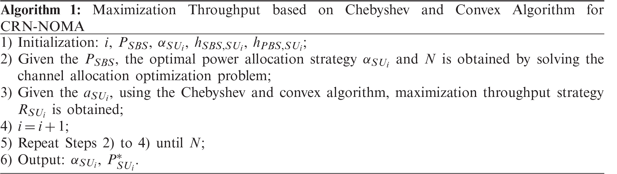
We propose a maximum throughput algorithm for CRN-NOMA based on Chebyshev and Convex optimization, which specific steps are shown in Algorithm 1. We mark this algorithm as MTCC.
4.3.1 Algorithm Convergence Analysis
Watkins proved the convergence of the Chebyshev algorithm under certain conditions [14]. As shown in this paper, if all actions are repeatedly sampled in all states and their action values are discretely represented, Chebyshev will converge to the optimal action value with a probability of 1.
4.3.2 Algorithm Time Complexity Analysis
Computational complexity issues are significant in all research aspects of CRN-NOMA. Reference [14] proposed that the computational complexity of the algorithm requires updating the power allocation aSUi and for each state. Therefore, its computational complexity is
5 Simulations and Results Analysis
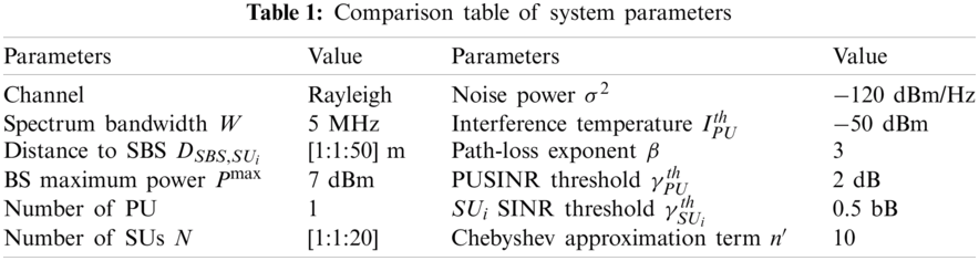
In this section, numerical simulations are used to evaluate the performance of the proposed algorithm. The simulation assumes that the network coverage is 150 and 150 m, where PBS, SBS, PU and SUs are randomly distributed in the network. The maximum distance from SU receiver to SBS is 50 m, and the fading follows Rayleigh distribution. The system simulation parameters are set as shown in Tab. 1. In addition, all simulation models and algorithms are coded in MATLAB 2015b, and the simulation value is the statistical average value calculated by Monte Carlo simulation based on channel randomness.
This part only simulates the downlink communication scenario of CRN-NOMA. Consider the mutual interference between PU and SUs, SUs and SUs. If the interference caused by SUs to PU causes the SINR of the PU to always be higher than its normal communication threshold, the SUs will not affect the normal communication of PU. The numerical data for the specific experiment is composed as follows.
As shown in Fig. 4, the number of SUs accessing CRN-NOMA is four. According to the distance from the SBS, four SUs are allocated different power allocation factors, i.e.,
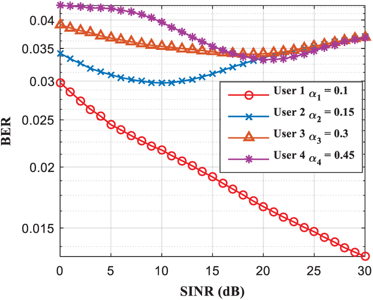
Figure 4: The change of power allocation factor to BER under different SINR conditions
Fig. 5 describes the difference performance between the NOMA scheme and the OMA scheme under the same constraints, and the comparison of the power performance of different numbers of SUs. This section considers using OFDMA scheme for comparison. It can be seen from Fig. 5 that the NOMA scheme has obvious advantages over the traditional OMA scheme. In addition, when the number of SUs exceeds10, the SUs power in this two schemes will be increased. The NOMA scheme has a greater performance gain compared to the OMA scheme, which also reflects that NOMA is more suitable for situations where the channel conditions between users differ greatly.
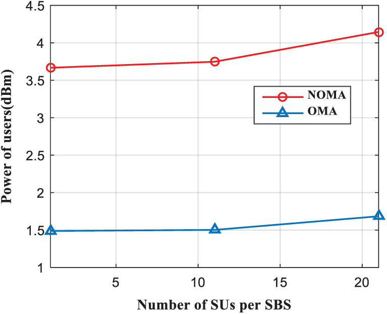
Figure 5: Power of different number of SUs per SBS
In the following, in order to evaluate the effectiveness of the proposed algorithm, we compare the algorithm with other power allocation algorithms. The legends “Optimal-NOMA,” “FTPA-NOMA” and “Optimal-OFDMA” respectively represent the power allocation scheme that proposed in this paper in the NOMA scenario, the fractional transmit power allocation (FTPA) scheme in the NOMA scenario and the power allocation scheme in the OFDMA scenario. The FTPA algorithm allocates power according to the size of the user channel gain and the pre-defined attenuation factor of the system [12]. If the attenuation factor is large, the power allocated to users with low channel gain is large. However, the distribution coefficients and attenuation factors in [15] are pre-defined by the system and are fixed. It is difficult to perform reasonable power allocation to the specific user channel quality conditions in the system. Therefore, the overall system performance is not optimal.
Fig. 6 illustrates the comparison of the sum throughput of system when running three different algorithms. The results show that the NOMA scheme can effectively improve the overall throughput of the system. For example, when the number of access SUs are four, the system throughput increases as the power of the four SUs increases. It can be seen from Fig. 6 that when the power is 1 dBm, the performance of the “Optimal-NOMA” and “FTPA-NOMA” algorithms are similar, with a throughput of about 21.2 Mpbs. But when the power increases, the performance of the “FTPA-NOMA” algorithm tends to decrease. The reason is that the power allocation of the “FTPA-NOMA” algorithm is insufficient, and some of the power is not allocated. However, the “Optimal-OFDMA” algorithm does not use the SIC technology, so its performance is poor.
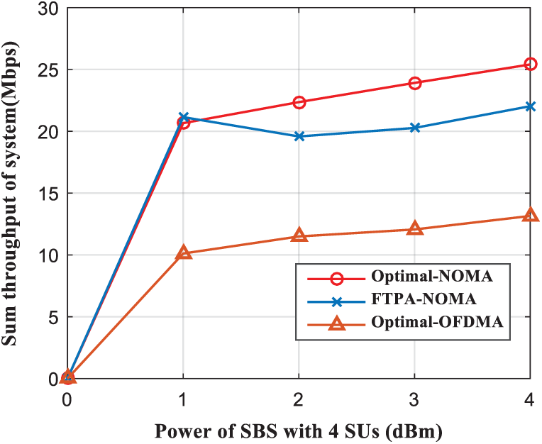
Figure 6: Sum throughput of system comparison as a function of the SBS power with four SUs
In Fig. 7, the average achievable throughput increases as the number of SUs per SBS increases. The more number of accessing SUs is, the greater average achievable throughput of the system will be. The number of SUs per SBS can access is up to 20. Compared with “Optimal-NOMA” and “FTPA-NOMA” algorithms, “Optimal-NOMA” achieves higher throughput. However, “Optimal-NOMA” achieves significantly higher throughput than “Optimal-OFDMA” algorithms. It can be seen that the NOMA scheme can effectively improve the average achievable throughput.
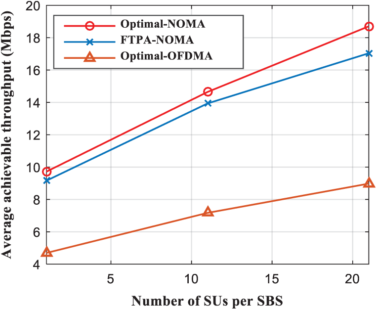
Figure 7: Average achievable throughput comparison as a function of the SUs number per SBS
Fig. 8 reveals how the system throughput varies with the power allocation factor. According to the principle of SIC technology, if a SU’s channel condition is relatively poor, the more power is allocated to this SU. It can be seen from Eqs. (6) and (7) that when the power allocation factor
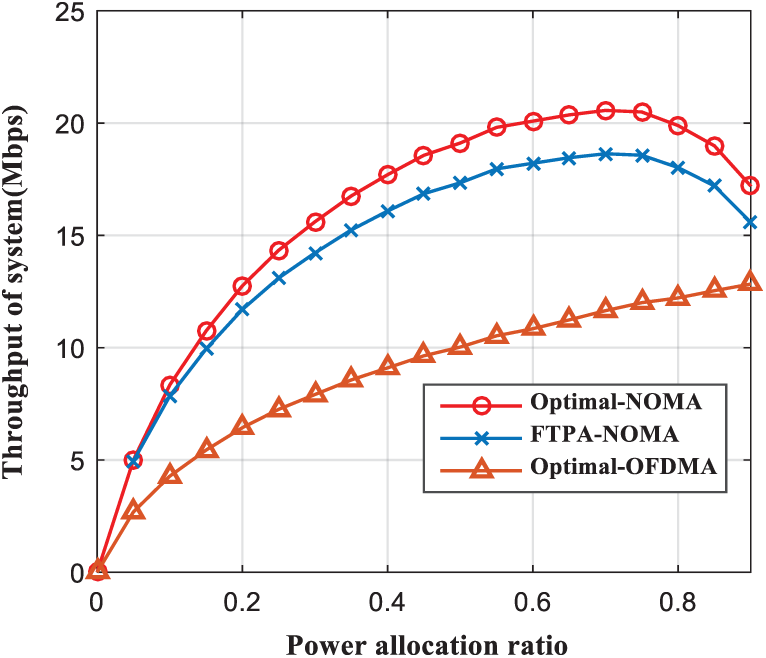
Figure 8: Throughput of system comparison as a function of the power allocation ratio
Fig. 9 is a bar graph that visually shows the throughput changes of the three algorithms with different numbers of SUs. When N = 1 , compared with the other two algorithms (i.e., “Optimal-OFDMA” and “FTPA-NOMA”), the performance of the “Optimal-NOMA” algorithm is better, and the average throughput of SUs can reach 8.85 Mbps. As the number of SUs increases, the average throughput of SUs also gradually increases. When the number of SUs is 4, the throughput increases most obviously. The reason for this change is that with NOMA technology, selecting the optimal number of SUs accesses can effectively improve system throughput.
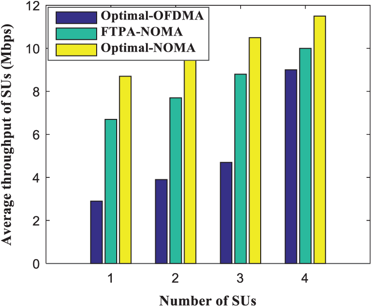
Figure 9: Average throughput of SUs comparison as a function of the SUs number
In summary, in the process of studying the optimal resources allocation of CRN-NOAM, we propose to use an adaptive method and a method of transforming Chebyshev inequality to convex optimization (MTCC) to solve two optimization problems, i.e., maximizing the number of SUs accessing SBS and maximizing system throughput. The objective of optimization is to maximize the number of access users and system throughput, and is constrained by QoS of PU and SUs, power control, interference constraints and power allocation factors. The Lagrangian duality method is used to transform the non-convex optimization problem into a convex optimization problem. Finally, the optimal heuristic algorithm is used to obtain the optimal solution. The algorithm MTCC proposed in this paper helps to improve the system throughput and spectrum utilization efficiency, and provides a reasonable resource allocation plan. Through experimental simulation, the effect is better than OMA’s power allocation scheme.
Acknowledgement: The authors would like to thank the anonymous reviewers for their selfless reviews and valuable comments, which have improved the quality of our original manuscript.
Funding Statement: This work was partially supported by the National Natural Science Foundation of China (Nos. 61876089, 61771410), by the Talent Introduction Project of Sichuan University of Science & Engineering (No. 2020RC22), by the Zigong City Key Science and Technology Program (No. 2019YYJC16), by the Enterprise Informatization and Internet of Things Measurement and Control Technology Sichuan Provincial Key Laboratory of universities (Nos. 2020WZJ02, 2014WYJ08), and by Artificial Intelligence Key Laboratory of Sichuan Province (No. 2015RYJ04).
Conflicts of Interest: The authors declare that they have no conflicts of interest to report regarding the present study.
1. Y. Zhang, J. Liu, Y. Peng, Y. Dong, G. Sun et al., “Performance analysis of relay based NOMA cooperative transmission under cognitive radio network,” Computers, Materials & Continua, vol. 63, no. 1, pp. 197–212, 2020. [Google Scholar]
2. L. Lv, J. Chen, Q. Ni, Z. Ding and H. Jiang, “Cognitive non-orthogonal multiple access with cooperative relaying: A new wireless frontier for 5G spectrum sharing,” IEEE Communications Magazine, vol. 56, no. 4, pp. 188–195, 2018. [Google Scholar]
3. L. Wang, J. Liu and A. Yang, “Analysis of underlay cognitive radio networks based on interference cancellation mechanism,” Computers, Materials & Continua, vol. 63, no. 1, pp. 401–416, 2020. [Google Scholar]
4. Y. Wang, Y. Wu, F. Zhou, Z. Chu, Y. Wu et al., “Multi-objective resource allocation in a NOMA cognitive radio network with a practical non-linear energy harvesting model,” IEEE Access, vol. 6, pp. 12973–12982, 2018. [Google Scholar]
5. J. Choi, “Power allocation for max-sum rate and max–min rate proportional fairness in NOMA,” IEEE Communications Letters, vol. 20, no. 10, pp. 2055–2058, 2016. [Google Scholar]
6. Z. Yang, Z. Ding, P. Fan and N. Al-Dhahir, “A general power allocation scheme to guarantee quality of service in downlink and uplink NOMA systems,” IEEE Transactions on Wireless Communications, vol. 15, no. 11, pp. 7244–7257, 2016. [Google Scholar]
7. X. Chen, R. Jia and D. W. K. Ng, “On the design of massive non-orthogonal multiple access with imperfect successive interference cancellation,” IEEE Transactions on Communications, vol. 67, no. 3, pp. 2539–2551, 2019. [Google Scholar]
8. J. Wu, L. Li, X. Ji and W. Shuang, “Power allocation for cognitive radio networks based on NOMA,” Journal of Shanghai Normal University (Natural Sciences), vol. 49, no. 1, pp. 31–36, 2020. [Google Scholar]
9. G. I. Tsiropoulos, O. A. Dobre and M. H. Ahmed, “Power allocation for cognitive radio networks M. Zengemploying non-orthogonal multiple access,” in 2016 IEEE Global Communications Conf., Washington, DC, pp. 1–5, 2016. [Google Scholar]
10. R. Alhamad and H. Boujema, “Optimal power allocation for CRN-NOMA systems with adaptive transmit power,” Signal Image and Video Processing, vol. 14, no. 8, pp. 1327–1334, 2020. [Google Scholar]
11. Y. Chu, B. Champagne and W. P. Zhu, “NOMA-based cooperative relaying for secondary transmissionin cognitive radio networks,” IET Communications, vol. 13, no. 12, pp. 1840–1851, 2019. [Google Scholar]
12. Y. Wu, L. P. Qian, H. Mao, X. Yang, H. Zhou et al., “Optimal power allocation and scheduling for non-orthogonal multiple access relay-assisted networks,” IEEE Transactions on Mobile Computing, vol. 17, no. 11, pp. 2591–2606, 2018. [Google Scholar]
13. Y. Liu, Z. Ding, M. Elkashlan and J. Yuan, “Non-orthogonal multiple access in large-scale underlay cognitive radio networks,” IEEE Transactions on Vehicular Technology, vol. 65, no. 12, pp. 10152–10157, 2016. [Google Scholar]
14. R. Jiao, L. Dai, J. Zhang, R. MacKenzie and M. Hao, “On the performance of NOMA-based cooperative relaying systems over ricianfading channels,” IEEE Transactions on Vehicular Technology, vol. 66, no. 12, pp. 11409–11413, 2017. [Google Scholar]
15. A. Benjebbour, A. Li, Y. Kishiyama, H. Jiang and T. Nakamura, “System-level performance of downlink NOMA combined with SU-MIMO for future LTE enhancements,” in 2014 IEEE Globecom Workshops, Austin, TX, pp. 706–710, 2014. [Google Scholar]
16. X. Wei, J. Liu, Y. Wang, C. Tang and Y. Hu, “Wireless edge caching based on content similarity in dynamic environments,” Journal of Systems Architecture, vol. 115, no. 1, pp. 102000–102013, 2021. [Google Scholar]
 | This work is licensed under a Creative Commons Attribution 4.0 International License, which permits unrestricted use, distribution, and reproduction in any medium, provided the original work is properly cited. |