DOI:10.32604/cmc.2021.018535
| Computers, Materials & Continua DOI:10.32604/cmc.2021.018535 | |
| Article |
Mathematical Morphology-Based Artificial Technique for Renewable Power Application
1Department of Electrical Engineering, Siksha ‘O’ Anusandhan University, Odisha, 751030, India
2Department of Electrical Electronics Engineering, Siksha ‘O’ Anusandhan University, Odisha, 751030, India
3College of Engineering at Wadi Addawaser, Prince Sattam bin Abdulaziz University, 11991, Saudi Arabia
*Corresponding Author: Buddhadeva Sahoo. Email: buddhadeva14@gmail.com
Received: 11 March 2021; Accepted: 14 April 2021
Abstract: This paper suggests a combined novel control strategy for DFIG based wind power systems (WPS) under both nonlinear and unbalanced load conditions. The combined control approach is designed by coordinating the machine side converter (MSC) and the load side converter (LSC) control approaches. The proposed MSC control approach is designed by using a model predictive control (MPC) approach to generate appropriate real and reactive power. The MSC controller selects an appropriate rotor voltage vector by using a minimized optimization cost function for the converter operation. It shows its superiority by eliminating the requirement of transformation, switching table, and the PWM techniques. The proposed MSC reduces the cost, complexity, and computational burden of the WPS. On the other hand, the LSC control approach is designed by using a mathematical morphological technique (MMT) for appropriate DC component extraction. Due to the appropriate DC-component extraction, the WPS can compensate the harmonics during both steady and dynamic states. Further, the LSC controller also provides active power filter operation even under the shutdown of WPS condition. To verify the applicability of coordinated control operation, the WPS-based microgrid system is tested under various test conditions. The proposed WPS is designed by using a MATLAB/Simulink software.
Keywords: Model predictive control; mathematical morphological technique; power quality; power reliability; wind power system; sensitive load
Due to the significant growth of grid integrated renewable energy-based distributed generators (DGs), the power quality (PQ) and reliability (PR) aspects have become a major challenge [1,2]. Traditionally, from an economic point of view, constant speed turbines with self-excited capacitors and induction generators (IGs) are chosen [3,4]. Though the traditional turbines function well at steady-state conditions, during dynamic states, a change in wind speed decreases the performance of the WPS. Therefore, to generate maximum power and to increase the durability of the WPS, DFIG based WPS are widely selected due to r high-power rating, improved damping operation, and requirement for lesser rating converters for integration [5,6]. The balanced grid performance is affected by using the non-linear/unbalanced load conditions such as inverters, SMPS, and chargers, etc. [7,8]. In unbalanced grid/distributed network conditions, the performance of WPS is affected because of the faltered electro-magnetic torque, change in rotor speed, and harmonic current injection. At that time, to protect the WPS from over voltage and current, it is necessary to disconnect the WPS from the disturbed network [9]. Due to the nonlinear load, the PQ and PR of the WPS are decreased by producing excess heating loss, decreasing the voltage quality, and increased power losses, etc. Therefore, the improvement of PQ and PR problems are considered as an important aspect of this study.
To overcome the PR issues, many researchers suggest various improved control methods for the operation of grid-connected double fed induction generator (DFIG) based WPS. From the literature, few important techniques such as the field-oriented control (FOC) or vector control (VC) approaches are widely applied for similar applications [10,11]. However, during the transient system conditions, the above-mentioned well-known strategies lag their performance due to the excess use of intricate decoupling methods and coordinate transformation. Moreover, these control strategies are also not concerned about the positive, negative, and zero sequence components. All these limitations will deteriorate the performance of the grid-integrated WPS. As a solution, to overcome the tuning problems and reduced the complexity in the control design of VC, novel direct torque control (DTC) [12,13], and direct power control (DPC) [14] approaches are proposed. As compare to the traditional FOC and VC, DTC and DPC strategies are much simpler and robust techniques to improve the PR operation. In recent days, to provide an enhanced operation, advanced DTC and DPC strategies are proposed for unbalanced DG integrated grid applications [15,16]. However, due to the use of hysteresis band regulator (HBR) and the use of switching tables, the advanced DTC and DPC strategies produce larger power ripples, which seriously deteriorate the DG performance. In [17], a predictive control technique is used to offer a fast-dynamic response. However, the predictive approach [17] was a comparatively complex control and faces difficulties during the implementation. In [18], a sliding mode approach (SMA) based control approach is suggested to regulate the DFIG based WPS. However, [18] is focused only on torque and reactive power regulation without considering the PQ enhancement of the WPS. An enhanced system design is projected in [19], to regulate both PR and PQ of WPS through a single controller design at the machine side. Undoubtedly, due to a single-loop control design, the implementation cost of the system is decreased to minimal value but rises the computational load and difficulty of the controller. In addition to that, if the generation is stopped then the complete system is stopped working and the demand for the load is not satisfied through the utility. Hence, it is essential to invent an optimal control solution to provide better PQ and PR aspects of the study.
To overcome the PQ issues, many researchers suggest various improved control approaches for the operation of grid-connected DFIG based WPS. In [20], to improve the PQ, a hypothetical control approach is proposed by using an instantaneous active and reactive power approach, similar to [21]. In [22], for reducing the complexity and computational burden, the power engineers calculated each of the current components through instantaneous power component definitions. However, due to the excess use of the decoupling and coordinate systems, the conventional PQ methods are incapable to detach the active and reactive current component in terms of positive and negative sequence components in a certain bound. In the DG integrations, due to the excess use of voltage source inverter and load, the performance of the WPS is exaggerated by the increased harmonic contaminations. As a solution, shunt active filter (SAF) based systems are one of the possible solutions for compensating the harmonics [23]. A similar type of SAF approach with the detailed working principle is proposed by considering different DGs and sensitive loads [24]. Still, the proposed approaches are designed by using the traditional
The major aspects of the study are presented as follows.
1. Detailed mathematical modeling of grid integrated DFIG based WPS is proposed for non-linear/unbalanced load applications.
2. To reduce the complexity in design and decrease the computational burden of the system, two novel coordinated control model is proposed as the machine side converter (MSC) and the load side converter (LSC) control approach.
3. To provide a continuous power supply and appropriate converter operation, an improved MPC controller is selected to develop the MSC controller for appropriate voltage vector generation and offer better power reliability operation.
4. To mitigate the harmonics obtained by the non-linear load, a novel current decomposition and MMT-based LPF is selected to develop the LSC controller for better PQ operation.
5. Due to the above-coordinated control approach, the LSC converter can perform as a SAF even during the shutdown condition of WPS.
2 Overall Wind Power System Modeling
The complete structure of the proposed DFIG based WPS is illustrated in Fig. 1. The dc-motor with two blades is connected to the DFIG through a gearbox, to provide an increased torque during lower speed action. As demonstrated in Fig. 1, the rotor winding of WPS is linked to the utility through two back-to-back voltage source converters (VSCs) such as MSC and LSC, and the stator winding is directly connected to the grid. The LSC is connected to the point of common coupling (PCC) through an interfacing inductor (Li), to protect the system from transient conditions. In this proposed approach, a non-linear/ unbalanced load is connected to the PCC, to illustrate the PQ aspects of the system. To offer better PR and PQ aspects of WPS, the control strategy of the proposed approach is divided into two sections as MSC control and LSC control. In the MSC approach, the MPC technique is used to regulate the real power of the machine and offer better PR operation. In the LSC approach, the MMT-based strategy is developed to mitigate the system nonlinearity and offer better PQ operation. Both of the proposed control strategies are interlinked with each other to offer a coordinated operation.
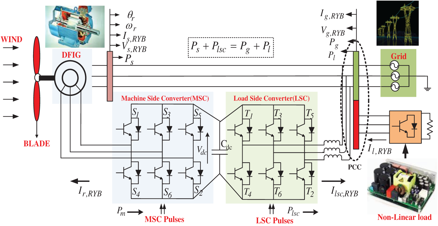
Figure 1: Overall system diagram of the DFIG based WPS
Before discussing about the proposed control strategy, it is essential to develop the detailed mathematical modeling of the undertaken DFIG based WPS. The block diagram and the phasor diagram of the DFIG model are illustrated in Fig. 2. The derived mathematical expressions of DFIG is presented as follows.
where Vs, dq and Is, dq are the dq stator voltage and current components, Vr, dq and Ir, dq are the rotor voltage and current component,
where Lm, Lms, and Lmr are denoted as the mutual inductance, stator mutual inductance, and rotor mutual inductance of the DFIG respectively. Rs is disregarded and
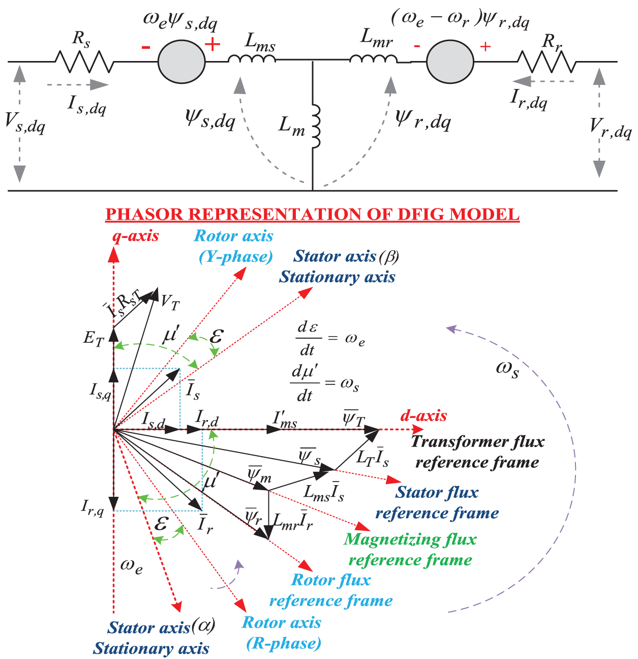
Figure 2: Block and phasor diagram of DFIG model
Substitute Eq. (5) in Eq. (6), Eq. (6) can be derived as.
The electrical torque ‘Te’ becomes
By using the complex conjugate of stator flux (
The complex power (S) of the system can be computed as.
where P is the real power and Q is the reactive power of the system.
To control the proposed DFIG based WPS, two control structures are required as MSC and LSC control approaches. The detailed explanations related to the proposed control approaches are presented in the following sections.
In this proposed approach, the MPC technique is selected to accurately forecast the requirement of real and reactive power demand of load and grid. After the accurate forecasting, the desired voltage vector is chosen by using the optimization cost function with properly tracking the forecasting value and the reference value. By neglecting the Rs, the relationship between the voltage (Vs) and flux (
By using Eqs. (3)–(5), the stator current ‘Is’ can be computed as.
where
By analyzing Eq. (13), the real and reactive power component is computed as.
Eqs. (14) and (15) illustrate that the stator’s real and reactive power output and depends upon the stator and rotor flux component. Generally, the stator flux is developed by using the constant grid frequency at 50 Hz and constant amplitude. Therefore, the real and reactive power developed from the machine depends upon the rotor flux, which is regulated by Vr, dq as described in Eq. (2). Based on the above concept, the MPC regulator requires to compute all the Vr, dq vectors based on the real stator power component. Before it is used for pulse generation, the voltage vector diminishes the cost function as illustrated in Fig. 3.
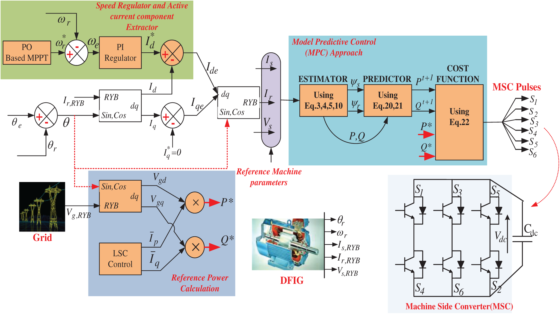
Figure 3: MSC control diagram
The time derivate of Eqs. (14) and (15) becomes
By canceling the rotor and stator resistance of Eqs. (16) and (17), the derivative of power becomes
It can be analyzed from Eqs. (18) and (19) that the mathematical modeling of DFIG can be developed by using the real and reactive power component as a state variable and the Vr, dq as an input respectively. By using the instantaneous power based on discrete-time responses, the next sampling responses of both active and reactive power (Pt+1 and Qt+1 ) can be estimated as.
where Tsample is denoted as the sampling time instant of the DFIG based WPS. After estimating the appropriate power requirement, the second step is to calculate the possible effects of the different Vr, dq, which is achieved due to different speeds and chosen one by diminishing the subsequent cost function (CF).
The complete MSC control approach is demonstrated in Fig. 3. As indicated in Fig. 3, by using the above mathematical equations the MSC controller is designed. For better understanding, the MSC controller is separated into three sections such as speed regulator, MPC controller, and reference power generation. In this proposed approach, for reference speed (
The LSC control approach is separated into two sections. The first section is proposed for a simpler control design by reducing the design complexity and computational burden, and the second section is proposed for an appropriate dc component extraction concept through a novel mathematic morphological technique (MMT) by reducing the harmonic and non-linearity current.
3.2.1 Advanced Ip-iq Approach (A-Ip-Iq-C)
The traditional Ip-Iq control (T-Ip-Iq-C) approach is designed by using a
In the A-Ip-Iq-C approach, during the
As per the PQ theory discussed in [7], the real current component (Ip) is determined by the product of the actual voltage and the current component. Likewise, the reactive current (Iq) component is determined by the product of actual voltage and current component with
By accumulating Eq. (2) in the matrix, it can be represented as.
where
The dc-components of Ip and Iq are denoted as
As illustrated in Eq. (26),
From Eq. (27), the matrix (Mb) is obtained for computing the phase currents from the fundamental current. By which the proposed controller knows the actual real and reactive current component through the phase currents without any conversion devices. The related equations are presented below.
where
By considering the fundamental and phase sequence voltage and current component, the proposed A-Ip-Iq-C approach has decreased the complexity and computational burden of the system by eliminating the
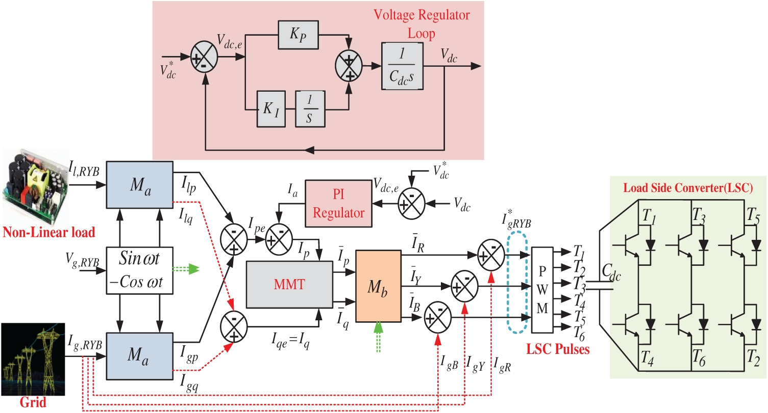
Figure 4: Proposed A-Ip-Iq-C approach for LSC
In Fig. 4, the dc-link voltage regulation block diagram is illustrated by using the actual and reference dc-link capacitor (Cdc) voltage rating. The real output current (Ia) response of the PI regulator is represented in time domain analysis form and can be represented as.
where KP is the proportional gain, and KI is the integral gain. From Eq. (29), the PI regulator transfer function is derived as.
As shown in Fig. 4, the open-loop GPI(s) and closed-loop HPI(s) transfer function of the PI regulator is represented as.
As shown in Eq. (32), HPI(s) is a second-order system and the denominator must be in the form of (
The constraints of the PI regulator are computed by sensing the actual and reference voltage component. To confirm the stability, the frequency response of GPI (s) at unlike bandwidth (BW=
The stability of the proposed approach is analyzed through different responses like frequency responses, impulse responses, and step responses respectively as indicated in Figs. 6a–6c respectively. Fig. 6a shows that the compared bode plot results of the proposed and conventional approach. During the proposed approach, it is observed that the phase margin and gain margin of the proposed system are 91.8
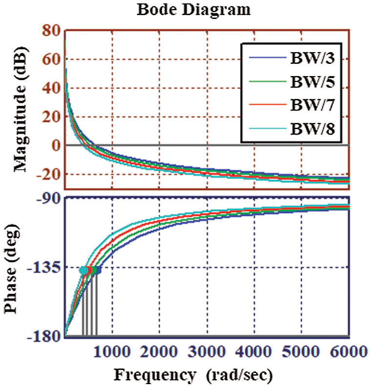
Figure 5: Frequency response of GPI(s) by using different bandwidth value
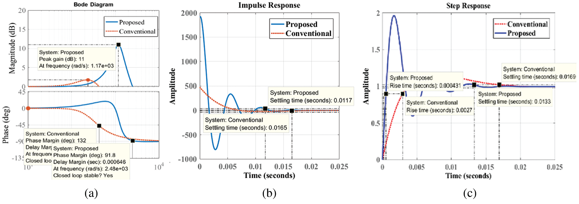
Figure 6: Stability responses of proposed and conventional system (a) Frequency response (b) Impulse response (c) Step response
After generating Ia from the proposed PI regulator, it is related to the IPe for producing the actual IP component. In the proposed approach, the Iqe is identical to the actual Iq component. To lessen the non-linear current component, the obtained Ip and Iq are passed through the dc-component extraction method based on MMT. By using the proposed MMT, the system can generate
MMT method is suggested for the appropriate real and reactive DC extraction. The design MMT model is illustrated in Fig. 7. MMT method depends upon the set theory and by using this theory the fundamental component is separated into two different sets. By using a shaping component (SC), one of the derived sets is tracked by other sets. ‘SC’ is used as a moving space, which moves among the signals combined with the space samples, and tracked useful signals/exact features of the sampled signals [28]. To operate the MMT, two important methods like corrosion and expansion are widely chosen. Based on the important methods, other complex methods like opening, closing, top-hat transform is selected for the modeling of MMT [29]. By analyzing the above methods, the most popular methods like corrosion, dilation, opening, and closing methods are chosen. The detailed mathematical explanation related to the MMT approach is described in the following sections.
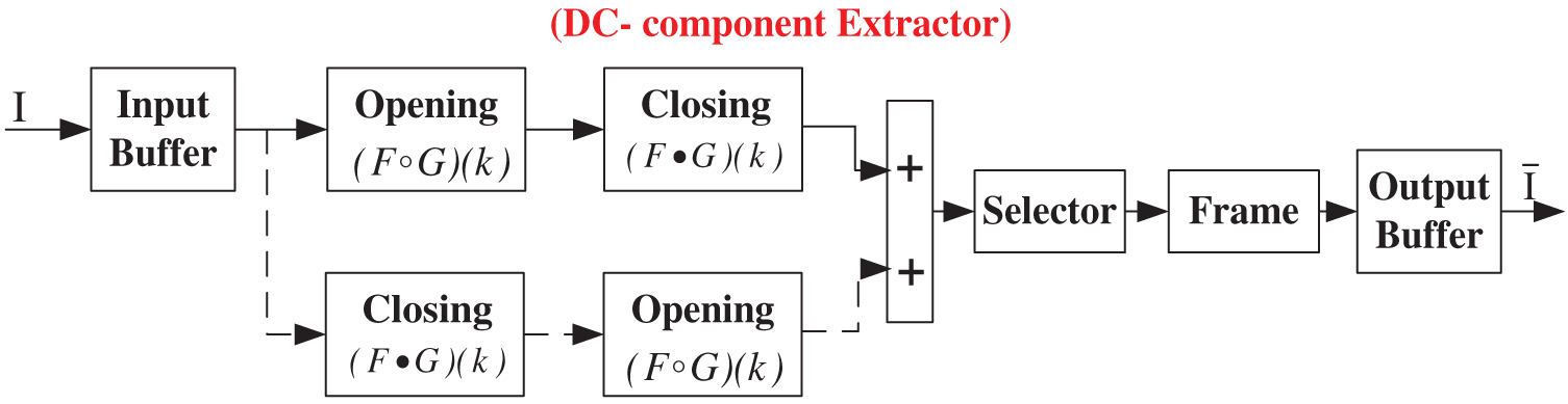
Figure 7: MMT method control diagram
To design the MMT approach, two sets like input current component F(k) and the SC G(s) are selected. The used domains of the selected sets are
In the proposed MMT technique, F is considered as the real and reactive input current components. From Eqs. 35 and 36, two resultant equations like opening and closing operations are developed.
The opening of ‘F(k)’ by SC ‘G(s)’ is expressed as.
Similarly, the closing of F (k) by G(s) is expressed as.
The important aim for selecting the opening (
Let Ym is the output of MMT at level ‘m’, and Gn is the ‘SC’ at level ‘n’. The new MMT filter is derived as.
At n = 1, F0 = F is the input current signal. Till the error between the output signal (Ym) and its previous value (Ym −1) is minimum, the iteration process is continued. The relation between Ym and Ym −1 can be derived as.
where
To justify the proposed MSC and LSC control approach need for the DFIG based WPS during nonlinear/unbalanced load conditions, different test conditions are presented in this section. Further, to give a clear idea about the improvement percentage (IP) of the proposed method, the obtained results are compared with the traditional STDPC [28] results. In this proposed approach, a 20 kW rated power-based WPS is designed and the performances of the WPS are studied during both steady-state and dynamic state conditions. At last, a comparative table is presented to show the improvement percentage of the proposed controller.
4.1 Testing the Performance of WPS by Using Traditional STDPC [28]
A Similar 20 kW rating of WPS performance is tested by using the traditional STDPC [28] technique. During the testing, the WPS is attached to a non-linear/unbalanced load. Generally, the sensitive load decreases the system performance drastically. By using the traditional STDPC approach, the undertaken WPS is tested at constant wind speed, without wind speed, fall in wind speed, and unbalanced load conditions respectively. Each test condition is undergone through non-linear load applications. Figs. 8a and 8b shows the current results and respective harmonic contained during different test conditions. Fig. 8a(i) shows the nonlinear load current and its rating is constant 12A in all of the test conditions. By using STDPC and at constant wind speed (10.6 m/s), the generated grid current (24A) and stator current (38A) from a 20 kW WPS as illustrated in Figs. 8a(ii,iii). Similarly, without wind speed, the WPS cannot able to produce power. Therefore, the stator current becomes zero, and the grid current around 12A is supplied to the sensitive load for satisfying the load requirement as illustrated in Fig. 8a(iv). Further, at a fall in wind speed, the grid current is gradually increased and the stator current is gradually decreased as illustrated in Figs. 8a(v,vi).
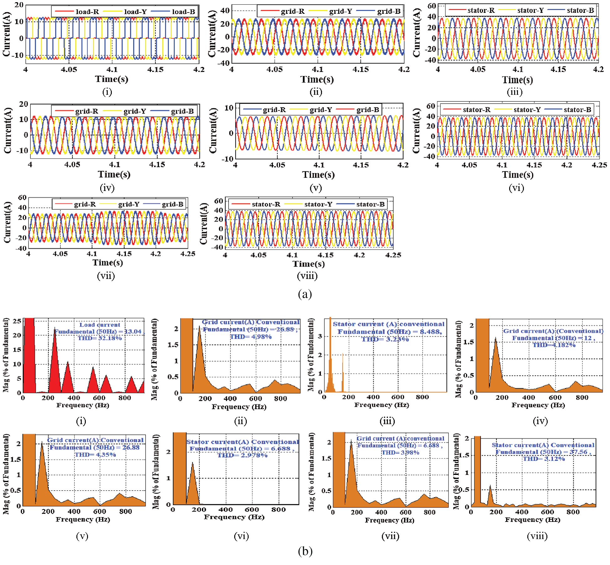
Figure 8: Output responses (a) Current responses of load, grid and stator (b) Harmonic current results of load, grid and stator (i) Non-linear load current (ii) Grid current during constant wind speed (iii) Stator current during constant speed (iv) Grid current during without wind speed (v) Grid current during fall in wind speed (vi) Stator current during fall in wind speed (vii) Grid current during unbalanced load (viii) Stator current during unbalanced load
Here only magnified figures are illustrated and the detailed explanation related to the undertaken conditions is provided in the following sections. At last, during an unbalanced load condition, the utility current is slightly increased to balance the non-linear load current. The respective stator and grid current outputs are demonstrated in Figs. 8a(vii,viii). Undoubtedly, as per the undertaken test condition, the controller performs accordingly. However, it is observed from the illustrated figures that the output current responses are not linear. Due to the non-linear nature of the grid and stator current, the system performance is affected badly. The non-linear nature of output waveforms shows that the traditional control approach is not enough competent during any transient conditions.
Moreover, to get more clarity about the performance of the traditional STDPC approach, in Fig. 8b the harmonic contained of the output waveforms are calculated by using Fast Fourier transform (FFT) technique. At first, the harmonic contained in the non-linear load is computed and found that it contains 32.18%. By using the traditional strategy, at constant wind speed, Figs. 8b(ii,iii) illustrates that the non-linear contained grid current and stator current is computed as 4.98% and 3.23% respectively. Similarly, without wind speed and non-linear load application, Fig. 8b(iv) illustrates that the non-linearity contained in the grid current is computed as 4.182%. During the fall in wind speed, Figs. 8b(v,vi) illustrates that the non-linearity contained in the grid and stator current is computed as 4.35% and 2.978% respectively. During unbalanced load conditions, Figs. 8b(vii,viii) shows that the harmonic contained of grid and stator current is computed as 3.98% and 3.12% respectively. From the harmonic analysis results, it is found that the harmonic percentage is very high as per the international IEEE-1541 limits. Due to the excess non-linearity contained in the output results, the PQ of the WPS is affected badly. Therefore, by analyzing the dynamic real-time conditions, there is a requirement to design an appropriate control strategy for the improvement of PQ/PR of the renewable integrated microgrid system.
4.2 Testing the Performance of WPS by Using the MSC and LSC Control Strategy
To test the performance of grid integrated WPS, it is undergone through different case studies like constant wind speed, without wind speed, gradually fall in wind speed, and unbalanced load condition. To show the effectiveness of the proposed MSC control approach, the power reliability conditions are illustrated by properly adjusting the real and reactive power flow. In addition to that, to show the effectiveness of the proposed LSC control approach, the power quality conditions are illustrated by compensating the generated harmonics. The corresponding test cases are presented in the following section.
Scenario-1: The test scenario is operated at constant wind speed (10.6 m/s). In this case, a 6.1 kw rating of the non-linear load is used to test both the PQ and PR aspects of proposed WPS. The respective wind speed (10.6 m/s) and nonlinear load current (12A) output results are demonstrated in Figs. 9(i,ii). Generally, the non-linear load affects the system performance by injecting the harmonic current. In the proposed approach, through LSC control the harmonic currents are compensated and improved the PQ. Similarly, MSC control regulates real and reactive power flow, to improve power reliability performance. To regulate the speed of the machine at a constant value (1750 rpm), P&O based MPA is chosen [23].
As per the proposed approach, the LSC generates appropriate harmonic current quadrature to the generated non-linear current as demonstrated in Fig. 9(iii). Due to the appropriate harmonic current generation at the LSC, the WPS has achieved a linear grid and stator current as 24A and 38A respectively. The corresponding current results are illustrated in Figs. 9(iv,v). The proposed WPS also achieved linear stator voltage as indicated in Fig. 9(vi). In this proposed approach, the nonlinear load power rating is set at 6.1 kW as illustrated in Fig. 9(vii). As the WPS rating is higher (20 kW) than the load demand (6.1 kW), the total power is transferred to both load and grid from the machine. Due to the system losses, the WPS generates 18.30 kW power from stator winding as demonstrated in Fig. 9(viii). Fig. 9(ix) illustrates that the LSC generates around 696.22 W power from the rotor winding of the machine. Therefore, the total power generated from the machine is computed as 19.1 kW. As the load demand is lesser than the generation, after feeding the load demand, the rest power around 12.871 kW power is transferred to the grid as illustrated in Fig. 9(x). Due to the appropriate power flow to the load and grid, it can be analyzed that by using the proposed MSC control strategy the WPS easily achieved the appropriate power reliability condition. Along with, to confirm the PQ conditions of the proposed WPS, the obtained current results are passed through FFT analysis. In the FFT analysis, the total harmonic distortion percentage of load current is 32.18% as illustrated in Fig. 9(xi). By using the proposed LSC control strategy, Figs. 9(xii,xiii) illustrates that the THD% of the grid and stator current is decreased significantly as 1.25% and 0.56% respectively. The obtained current harmonic contained values lie in between the desirable specified IEEE-1541 standard values. Therefore, it is proposed to run the real-time microgrid system with the proposed MSC and LSC control approach.
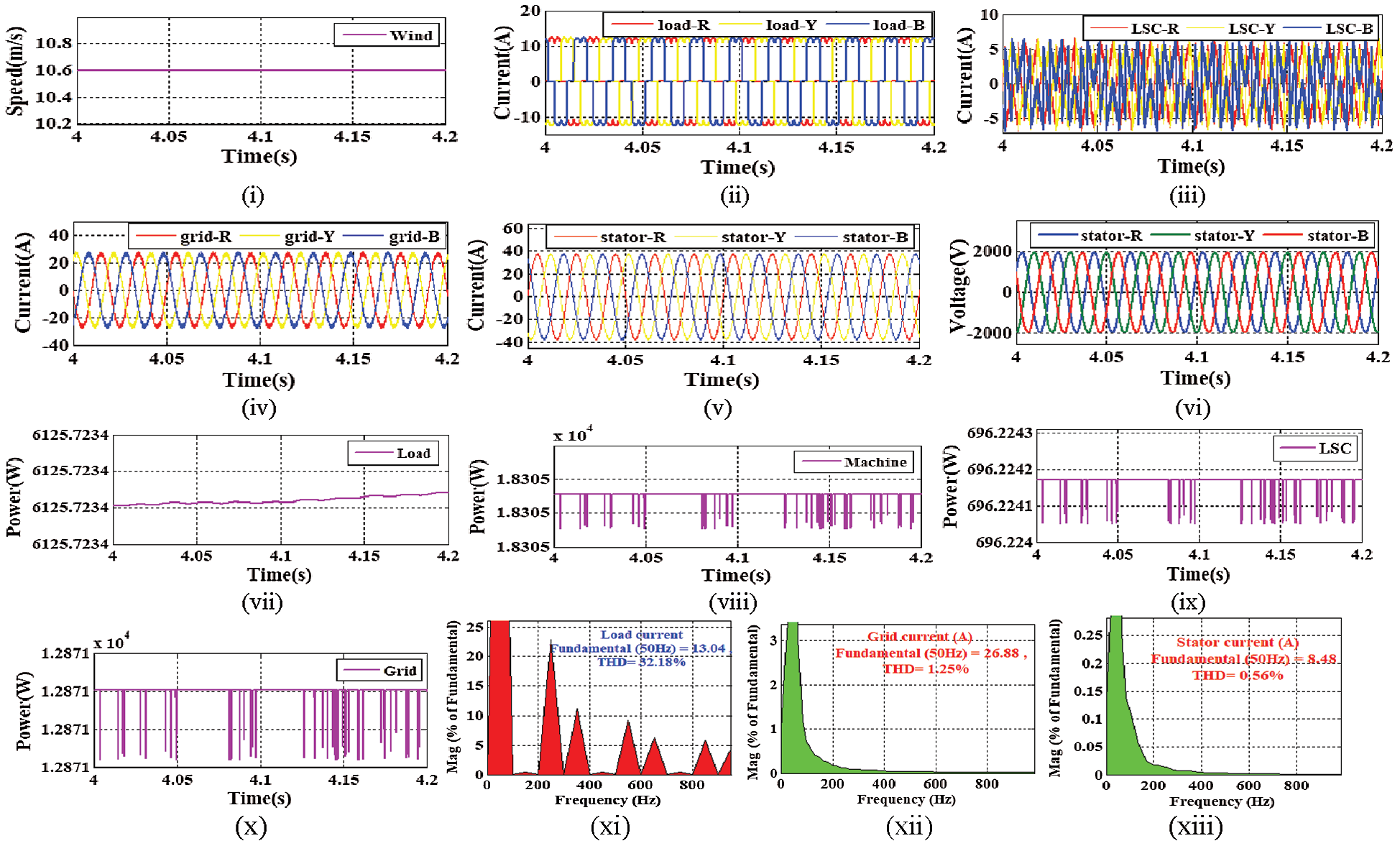
Figure 9: Output results (i) Wind speed (ii) Load current (iii) LSC current (iv) Grid current (v) Stator current (vi) Stator voltage (vii) Load power (viii) Machine real power (ix) LSC real power (x) Grid real power (xi) THD of load current (xii) THD of grid current (xiii) THD of stator current
Scenario-2: This test scenario is operated without wind speed conditions. Due to the absence of wind, the stator power of the machine becomes zero. Similar to the above scenario, in this test scenario also the power quality and reliable operation are tested in the absence of WPS. In this test scenario, the load demand is set to 6.6 kW real and 1.2 kVar reactive power.
As per the load demand, Fig. 10(i) illustrates the load current output results as 12 A. The proposed DFIG based WPS is operated in a coordinated manner. Due to the coordinated/interlinked controller design, the proposed LSC controller generates the required harmonic current orthogonal to the produced non-linear load current as demonstrated in Fig. 10(ii). Therefore, the WPS achieves a linear 12A grid current as illustrated in Fig. 10(iii). The stator voltage results are demonstrated in Fig. 10(iv). From the obtained output current results, it is observed that the current responses are linear as compared to the traditional STDPC approach [12]. The desired output real (6.6 kW) and reactive (1.2 kVar) power demand of the non-linear load is illustrated in Figs. 10(v,vi). Due to the coordinate control approach, to meet the load reactive power requirement and compensating the harmonics, the LSC generates 0.1 kW real and 600 kVar reactive power as illustrated in Figs. 10(vii,viii), and the rest power is provided by the grid around 7.7 kW real and 0 kVar reactive power as demonstrated in Figs. 10(ix,x). Generally, the load active power demand is 6.6 kW only then the rest real grid power around 600W is converted to the reactive power through the LSC approach to meet the load reactive power demand (1.2 kVar). Therefore, the additional converter requirement is eliminated for further conversion of real to reactive grid power. In this scenario, the grid and LSC power results become ‘ −ve’ sign because the power is flown in the opposite direction. In this way, the proposed controller achieves the power reliability condition. Similarly, to achieve better power quality operation, the obtained currents are passed through FFT analysis. During the FFT analysis process, the load and grid current THD% is computed as 32.18% and 0.98% respectively, as illustrated in Figs. 10(xi,xii). As per the international standards, the computed harmonic percentage is much lesser than the traditional approach results. Therefore, it is proposed to run the real-time microgrid system with the proposed MSC and LSC controller approach.
Scenario-3: This scenario is tested with a fall in wind speed conditions. Similar to the above scenarios, in this test scenario also the power quality and reliable operation are tested. In this test Scenario, the load demand is set to 6.6 kW real power.
Fig. 11(i) shows that the wind speed is gradually decreased from 10.6 m/s. In this Scenario, to achieve 6.6 kW load power demand, the load current around 12A is illustrated in Fig. 11(ii). The dynamic conditions are illustrated in between 4 to 6 s time interval. Before 4–6 s, the WPS is operated at constant wind speed. Due to the proposed MSC and LSC control approach, the proposed WPS has achieved a linear grid and stator current as illustrated in Figs. 11(iii,iv). Fig. 11(iii) illustrates that the grid current is gradually increased due to the fall in wind speed, and Fig. 11(iv) illustrates that the stator current gradually decreases due to the fall in wind speed. Initially, due to constant and appropriate wind speed, the WPS is capable to generate the energy and fed both load and grid. However, due to the fall in wind speed, the grid supplies power to meet the load and machine requirement. Therefore, the grid current is gradually increased and the stator current is decreased. Due to the dynamic change in wind speed and machine performance, the rotor current is also affected and illustrated in Fig. 11(v). However, due to the proposed approach, the current waveforms become linear during the presence of a similar rating of non-linear load. Further, in this condition, the rotor speed and reference speed are also decreased from its synchronous speed to sub-synchronous speed. The slip sign is also changed from ‘ −ve’ to ‘+ve’. The decreased in rotor speed is illustrated in Fig. 11(vi). The load demand is illustrated in Fig. 11(vii). During the fall in wind speed, the power is flown from the grid to load and machine. Therefore, the LSC real power is represented in the opposite sign as illustrated in Fig. 11(viii). Due to the grid supplies more power to meet the load requirement, the grid power also changed from ‘+ve’ to ‘ −ve’ as illustrated in Fig. 11(ix). Due to the proposed approach, during the fall in wind speed, the stator real power is decreased, and to compensate the harmonic and offer reactive power support to the load, the stator reactive power is gradually improved as illustrated in Figs. 11(x,xi). That indicates, the proposed WPS achieved better power reliability operating during the dynamic change in wind speed. Further, to test the power quality aspect of the study, the generated current results are passed through FFT analysis. From the FFT analysis, it is found that at the same 32.18% of harmonic load, the grid and stator current harmonic contained is decreased significantly to 1.59% and 1.19% respectively, as illustrated in Figs. 11(xii–xiv). This is very less as compared to the traditional STDPC approach. Therefore, it is proposed to run the real-time microgrid system with the proposed MSC and LSC controller approach.
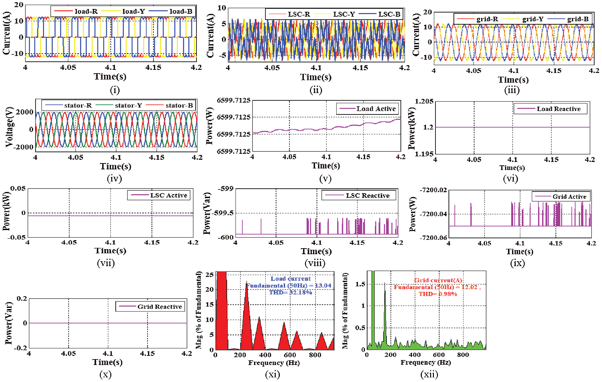
Figure 10: Output results (i) Load current (ii) LSC current (iii) Grid current (iv) Stator voltage (v) Load real power (vi) Load reactive power (vii) LSC real power (viii) LSC reactive power (ix) Grid real power (x) Grid reactive power (xi) THD of load current (xii) THD of grid current
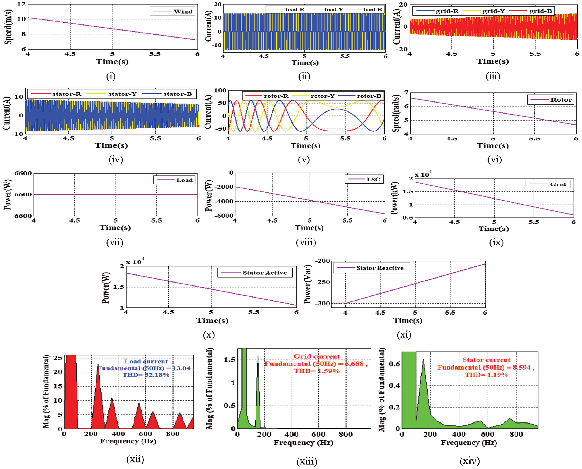
Figure 11: Output results (i) Wind speed (ii) Load current (iii) Grid current (iv) Stator current (v) Rotor current (vi) Rotor speed (vii) Load power (viii) LSC real power (ix) Grid real power (x) Stator real power (xi) Stator reactive power (xii) THD of load current (xiii) THD of grid current (xiv) THD of stator current
Scenario-4: This scenario is tested with an unbalanced load condition. Similar to the above scenarios, the PQ operation is tested. In this scenario, the nonlinear load is converted to an unbalanced load. The load current result is illustrated in Fig. 12(i). To convert the sensitive load into the unbalanced load, one phase ‘R’ is detached by the circuit breaker in between 4.1 s −4.2 s. To compensate the unbalanced and non-linear situation, the proposed LSC generates harmonic and unbalanced currents as demonstrated in Fig. 12(ii). Due to the unbalanced load current, as shown in Fig. 12(ii) suddenly R phase of the LSC current is increased to balance the load current. During that period, the grid current also increases its amplitude as illustrated in Fig. 12(iii). The proposed MSC and LSC control approach does not hamper the machine performance. Therefore, the WPS generates constant stator voltage and current as illustrated in Figs. 12(iv,v). To check the power quality aspect of the study, the obtained current results are passed through FFT analysis. From the FFT analysis report, it is clear that during 25.44% of harmonic current, the harmonic contained of grid and stator current becomes 1.28% and 0.78% respectively, as illustrated in Figs. 11(vi–viii). Therefore, it is proposed to run the real-time microgrid system with the proposed MSC and LSC controller approach.
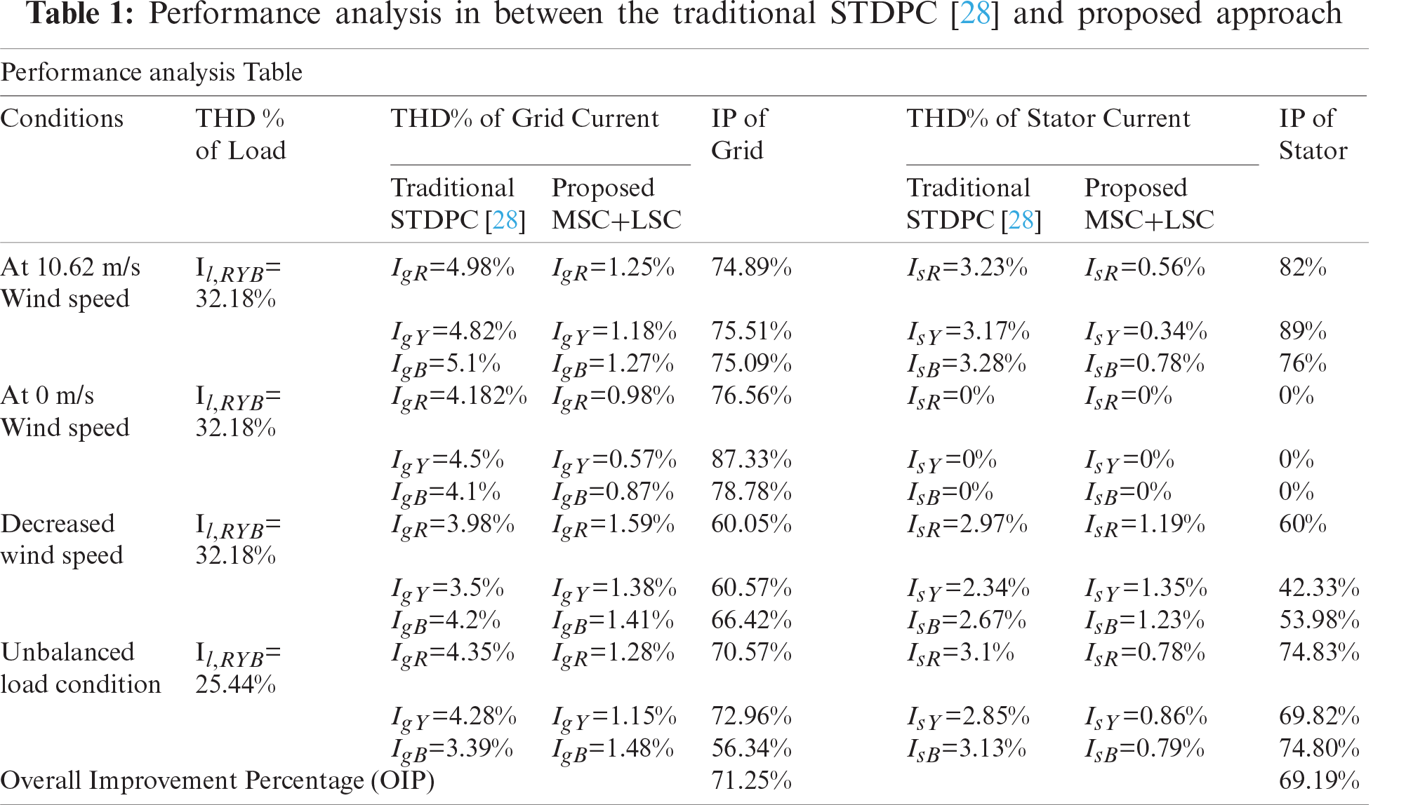
Scenario-5: In this scenario, a comparative analysis section is presented to illustrate the importance of the proposed control strategy over the traditional STDPC strategy [28]. To show the improvement percentage (IP) of the proposed approach over traditional STDPC, a performance analysis table is presented by considering the THD% of grid and stator current in Tab. 1. The THD% of grid and stator current is computed by considering all of the above test conditions such as constant wind speed, without wind speed, fall in wind speed, and unbalanced load condition. By analyzing the proposed and traditional THD%, IP is computed for both grid and stator current results. Closely observing the IP results, overall IP is computed for both grid and stator current. It is found that the overall IP (OIP) for grid current is 71.25% and the OIP of stator current is 69.19%. It is observed that both of the OIP is almost equal to each other during steady-state and dynamic conditions. By analyzing the above results, the improved robustness and better accuracy of the controller are also checked. Therefore, it is suggested to implement the combined MSC and LSC controller for real-time microgrid system.
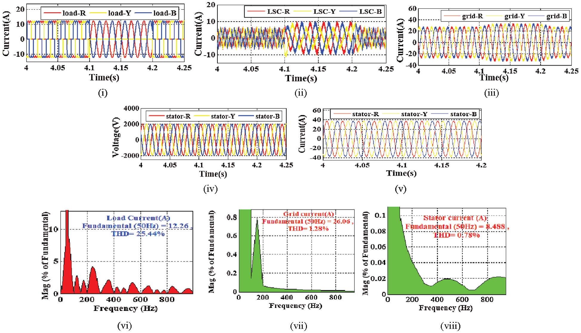
Figure 12: Output results (i) Load current (ii) LSC current (iii) Grid current (iv) Stator voltage (v) Stator current (vi) THD of load current (vii) THD of grid current (xvii) THD of stator current
In this proposed approach, a simplified and coordinated MSC and LSC controller approach is proposed for DFIG based WPS under sensitive load conditions. The important contribution of the paper is to use the MPC technique for appropriate switching pulse generation to operate MSC. Due to the proposed approach, the appropriate rotor voltage is selected according to the minimum cost function in every sampling instant. In addition to that, the design of the MSC controller avoids any switching tables, transformation techniques, and PWM techniques. Therefore, the proposed MSC approach improves the PR operation during both steady and dynamic state operations. On the other hand, the proposed LSC control approach is proposed for offering better PQ of the DFIG based microgrid system. MMT based LSC controller is used to extract the fundamental load current component. By using the LSC approach, the system able to improve PQ by compensating the harmonic component generated by the sensitive load. Further, in the shutdown condition of the WPS, the LSC controller also facilitate the active power filter operation by taking power from the grid. Therefore, the overall performance of the WPS is improved by using the coordinated MSC and LSC approach. The above obtained and analyzed simulated outcomes used as a basis of both MSC and LSC approach for the WPS on a real-time system application.
Acknowledgement: Assistance provided by Council of scientific and industrial research (CSIR), Government of India, under the acknowledgment number 143460/2K19/1 (File: 09/969(0013)/2K20-EMR-I) and Siksha O Anusandhan (Deemed to be University).
Funding Statement: Funding is provided by Council of scientific and industrial research (CSIR).
Conflicts of Interest: The authors declare that they have no conflicts of interest to report regarding the present study.
1. B. Sahoo, S. K. Routray and P. K. Rout, “Artificial neural network-based PI-controlled reduced switch cascaded multilevel inverter operation in wind energy conversion system with solid-state transformer,” Iranian journal of science and technology Transactions of Electrical Engineering, vol. 43, no. 4, pp. 1053–1073, 2019. [Google Scholar]
2. O. P. Mahela, N. Gupta, M. Khosravy and N. Patel, “Comprehensive overview of low voltage ride through methods of grid integrated wind generator,” IEEE Access, vol. 7, pp. 99299–99326, 2019. [Google Scholar]
3. A. Fernández-Guillamón, K. Das, N. A. Cutululis and Á. Molina-García, “Offshore wind power integration into future power systems: Overview and trends,” Journal of Marine Science and Engineering, vol. 7, no. 11, pp. 399, 2019. [Google Scholar]
4. B. Sahoo, S. K. Routray and P. K. Rout, “Robust control approach for the integration of DC-grid based wind energy conversion system,” IET Energy Systems Integration, vol. 2, no. 3, pp. 215–225, 2020. [Google Scholar]
5. M. Baharani, M. Biglarbegian, P. Babak and T. Hamed, “Real-time deep learning at the edge for scalable reliability modeling of Si-mOSFET power electronics converters,” IEEE Internet of Things Journal, vol. 6, no. 5, pp. 7375–7385, 2019. [Google Scholar]
6. L. Xiong, P. Li, F. Wu, M. Ma, M. W. Khan et al., “A coordinated high-order sliding mode control of DFIG wind turbine for power optimization and grid synchronization,” International Journal of Electrical Power & Energy Systems, vol. 105, pp. 679–689, 2019. [Google Scholar]
7. B. Sahoo, S. K. Routray and P. K. Rout, “A new topology with the repetitive controller of a reduced switch seven-level cascaded inverter for a solar PV-battery based microgrid,” Engineering Science and Technology, an International Journal, vol. 21, no. 4, pp. 639–653, 2018. [Google Scholar]
8. V. Yaramasu, A. Dekka, M. J. Durán, S. Kouro and B. Wu, “PMSG-Based wind energy conversion systems: Survey on power converters and controls,” IET Electric Power Applications, vol. 11, no. 6, pp. 956–968, 2018. [Google Scholar]
9. B. Sahoo, S. K. Routray and P. K. Rout, “Application of mathematical morphology for power quality improvement in microgrid,” International Transactions on Electrical Energy Systems, vol. 30, no. 5, pp. e12329, 2020. [Google Scholar]
10. A. K. Mondal and P. Bera, “Design of PI controller of wind turbine with doubly fed induction generator using flower pollination algorithm,” In Advances in Communication, Devices and Networking, Springer, Singapore, pp. 755–766, 2018. [Google Scholar]
11. W. E. Vanço, F. B. Silva and J. R. B. A. Monteiro, “A study of the impacts caused by unbalanced voltage (2%) in isolated synchronous generators,” IEEE Access, vol. 7, pp. 72956–72963, 2019. [Google Scholar]
12. S. K. Routray, B. Sahoo, and S. S. Dash, “A novel control approach for multi-level inverter-based microgrid,” In Advances in Electrical Control and Signal Systems, Springer, Singapore, pp. 983–996, 2020. [Google Scholar]
13. K. M. Muttaqi and M. T. Hagh, “A synchronization control technique for soft connection of doubly-fed induction generator-based wind turbines to the power grid,” IEEE Industry Applications Society Annual Meeting, Cincinnati, OH, USA, IEEE, pp. 1–7, 2017. [Google Scholar]
14. B. Sahoo, S. K. Routray and P. K. Rout, “A novel centralized energy management approach for power quality improvement,” In International Transactions on Electrical Energy Systems, pp. e12582, 2020. [Google Scholar]
15. P. F. C. Gonçalves, S. M. A. Cruz and A. M. S. Mendes, “Fault-tolerant predictive control of a doubly-fed induction generator with minimal hardware requirements,” in IECON 2018-44th Annual Conf. of the IEEE Industrial Electronics Society, Washington, DC, USA, IEEE, pp. 3357–3362, 2018. [Google Scholar]
16. B. Sahoo, S. K. Routray and P. K. Rout, “Hybrid generalised power theory for power quality enhancement,” IET Energy Systems Integration, vol. 2, no. 4, pp. 404–414, 2020. [Google Scholar]
17. H. Nian, C. Cheng and Y. Song, “Coordinated control of DFIG system based on repetitive control strategy under generalized harmonic grid voltages,” Journal of Power Electronics, vol. 17, no. 3, pp. 733–743, 2017. [Google Scholar]
18. W. Jin, Y. Li, G. Sun, X. Chen and Y. Gao, “Stability analysis method for three-phase multi-functional grid-connected inverters with unbalanced local loads considering the active imbalance compensation,” IEEE Access, vol. 6, pp. 54865–54875, 2018. [Google Scholar]
19. B. Sahoo, S. K. Routray and P. K. Rout, “A novel control strategy based on hybrid instantaneous theory decoupled approach for PQ improvement in PV systems with energy storage devices and cascaded multi-level inverter,” Sadhana, vol. 45, no. 1, pp. 1–13, 2020. [Google Scholar]
20. Z. Zeng, X. Li and W. Shao, “Multi-functional grid-connected inverter: Upgrading distributed generator with ancillary services,” IET Renewable Power Generation, vol. 12, no. 7, pp. 797–805, 2018. [Google Scholar]
21. B. Sahoo, S. K. Routray and P. K. Rout, “Robust control approach for stability and power quality improvement in electric car,” International Transactions on Electrical Energy Systems, vol. 30, no. 12, pp. e12628, 2020. [Google Scholar]
22. A. K. K. Giri, S. R. Arya, R. Maurya and B. C. Babu, “Power quality improvement in stand-alone SEIG-based distributed generation system using lorentzian norm adaptive filter,” IEEE Transactions on Industry Applications, vol. 54, no. 5, pp. 5256–5266, 2018. [Google Scholar]
23. B. Sahoo, S. K. Routray and P. K. Rout, “A novel sensorless current shaping control approach for SVPWM inverter with voltage disturbance rejection in a dc grid–based wind power generation system,” Wind Energy, vol. 23, no. 4, pp. 986–1005, 2020. [Google Scholar]
24. S. Dewangan and S. Vadhera, “Performance improvement of three-phase wind-driven SEIG using adaptive neuro-fuzzy inference system,” International Transactions on Electrical Energy Systems, vol. 30, no. 4, pp. e12269, 2020. [Google Scholar]
25. Y. Shen, M. Abubakar, H. Liu and F. Hussain, “Power quality disturbance monitoring and classification based on improved PCA and convolution neural network for wind-grid distribution systems,” Energies, vol. 12, no. 7, pp. 1280, 2019. [Google Scholar]
26. B. Sahoo, S. K. Routray and P. K. Rout, “Integration of wind power generation through an enhanced instantaneous power theory,” IET Energy Systems Integration, vol. 2, no. 3, pp. 196–206, 2020. [Google Scholar]
27. B. Sahoo, S. K. Routray and P. K. Rout, “Execution of robust dynamic sliding mode control for smart photovoltaic application,” Sustainable Energy Technologies and Assessments, vol. 45, pp. 101150, 2021. [Google Scholar]
28. B. B. Pimple, V. Y. Vekhande and B. G. Fernandes. “New direct torque control of DFIG under balanced and unbalanced grid voltage,” in TENCON 2010-2010 IEEE Region 10 Conference, Fukuoka, Japan, IEEE, pp. 2154–2158, 2010. [Google Scholar]
29. B. Sahoo, S. K. Routray and P. K. Rout, “AC, DC, and hybrid control strategies for smart microgrid application: A review,” International Transactions on Electrical Energy Systems, vol. 31, no. 1, pp. e12683, 2020. [Google Scholar]
30. B. Sahoo, S. K. Routray and P. K. Rout, “Advanced speed-and-current control approach for dynamic electric car modelling,” IET Electrical Systems in Transportation, 2021. https://doi.org/10.1049/els2.12015. [Google Scholar]
Appendix
WPS: Maximum Power (Pm) = 20 kW, Wind speed = 10.6 m/s. Generator data: Apparent Power (Pa) = 5.69 kVA, Frequency (F) = 50 Hz, Stator and rotor turns ratio
 | This work is licensed under a Creative Commons Attribution 4.0 International License, which permits unrestricted use, distribution, and reproduction in any medium, provided the original work is properly cited. |