DOI:10.32604/cmc.2021.017797
| Computers, Materials & Continua DOI:10.32604/cmc.2021.017797 | |
| Article |
A 3D Measurement Method Based on Coded Image
1Institute of Mechanics, North China University of Water Resources and Electric Power, Zhengzhou, 450011, China
2IT Fundamentals and Education Technologies Applications, University of Information Technology and Management in Rzeszow, Rzeszow, 100031, Poland
*Corresponding Author: Jinxing Niu. Email: njx.mail@163.com
Received: 11 February 2021; Accepted: 11 April 2021
Abstract: The binocular stereo vision system is often used to reconstruct 3D point clouds of an object. However, it is challenging to find effective matching points in two object images with similar color or less texture. This will lead to mismatching by using the stereo matching algorithm to calculate the disparity map. In this context, the object can’t be reconstructed precisely. As a countermeasure, this study proposes to combine the Gray code fringe projection with the binocular camera as well as to generate denser point clouds by projecting an active light source to increase the texture of the object, which greatly reduces the reconstruction error caused by the lack of texture. Due to the limitation of the camera viewing angle, a one-perspective binocular camera can only reconstruct the 2.5D model of an object. To obtain the 3D model of an object, point clouds obtained from multiple-view images are processed by coarse registration using the coarse SAC-IA algorithm and fine registration using the ICP algorithm, which is followed by voxel filtering fusion of the point cloud. To improve the reconstruction quality, a polarizer is mounted in front of the cameras to filter out the redundant reflected light. Eventually, the 3D model and the dimension of a vase are obtained after calibration.
Keywords: 3D reconstruction; structural light; SAC-IA; ICP; voxel filtering
Artificial intelligence-based computer vision has been replacing human vision in many fields, because of its excellent performance in describing and recognizing the objective world by processing camera-captured images. Specifically, it is expected to perform like the human visual system to process three-dimensional (3D) images, achievement of which can be greatly helpful for research and development in the industry [1–3]. For instance, it can help accurately identify the defective parts of an object with a high efficiency, which greatly reduces the workload that is originally done by humans.
As one of the most representative technologies in the field of optical 3D measurement, the fringe projection technology is favored by various features, including non-contact, high universality, high resolution, high precision, and high speed [4,5]. Meanwhile, the binocular stereo vision and coded light method has been commonly used to reconstruct and measure 3D objects in many fields (e.g. industrial production, cultural relic protection, and 3D printing) [6–8], and they have the advantages of low equipment cost and high model accuracy. In this study, the fringe projection technology is used to reconstruct and measure a 3D object, which is accompanied by analyses of (1) the principle of binocular camera imaging, calibration, and correction, (2) stereo matching algorithms, such as the block matching (BM) algorithm and the semi-global stereo matching (SGBM) algorithm, (3) performances of the integrated binocular camera and Gray code fringe projection in reconstructing a single perspective model of an object, (4) roles of coarse- and fine-registration algorithms in generating point clouds, and (5) effects of the integration of sample consensus initial alignment (SAC-IA) and iterative closest point (ICP) algorithms. Eventually, a complete 3D model of a vase is established after point cloud fusion processing, followed by the corresponding reconstruction error analysis.
The principle of stereo vision technology is to reverse the camera imaging process that projects 3D points in the real world to a 2D image plane, which can be simply described by the pinhole imaging model [9], as illustrated in Fig. 1.
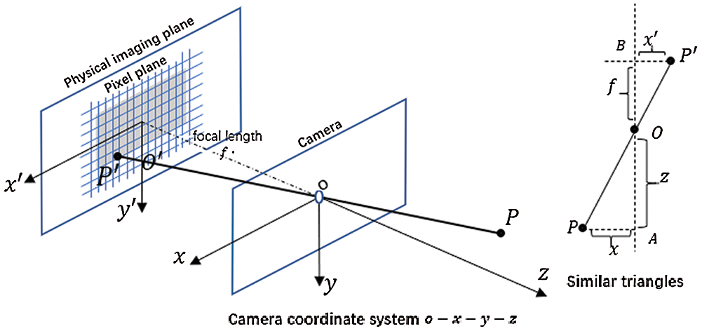
Figure 1: Pinhole imaging model
According to the similar relationship of the triangles, the following relationship exists:
where Z is blabla, f is the focal length of the camera, X is blabla, X’ is blabla, Y is blabla, Y’ is blabla, and the sign in the formula indicates the direction, which is positive from left to right.
There are three coordinate systems, namely the pixel coordinate system, the camera coordinate system, and the world coordinate system (Fig. 2). Therefore, it is necessary to establish a conversion relationship between the object point and the image point.
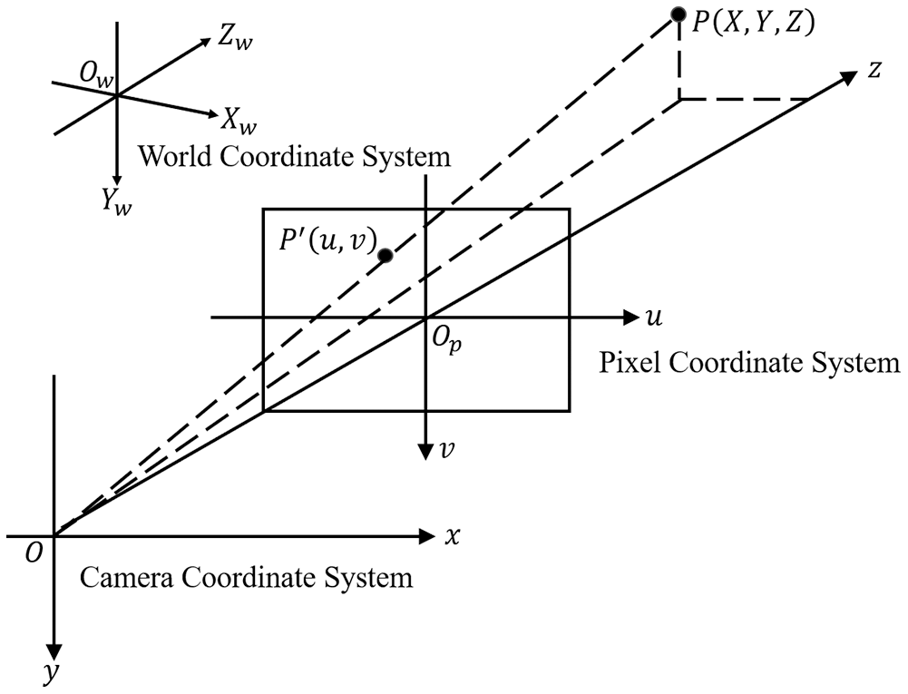
Figure 2: The relationship between three coordinate systems
Camera calibration is to calculate the internal and external parameters of the imaging system. Specifically, the structured light system calibration essentially determines the relationship between a point in the world coordinate system and the counterpart in the camera coordinate system [9]. A diffuse reflection board is used in this study for calibration (Fig. 3), which has a black and white checkerboard pattern with
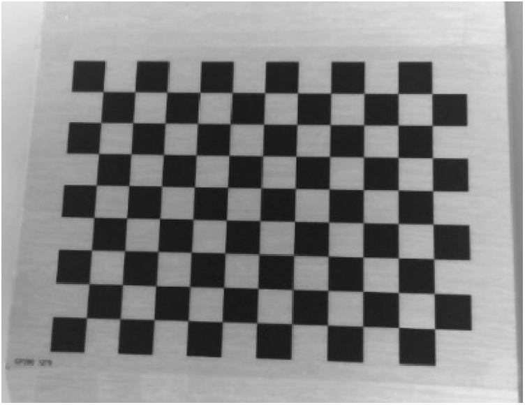
Figure 3: Diffuse reflection calibration board
Stereo matching is the key to 3D reconstruction, since it affects directly the accuracy of the reconstructed 3D model. BM and SGBM algorithms are commonly used for local stereo matching [11], and the matching units are generally associated with the image features, such as corners, contour edges, and inflection points. When applying the feature-based stereo matching algorithm, the first step is to extract the feature regions of the left and right images, while the second step is to take the left image as the reference and find the matching points on the corresponding bipolar line in the right image. The sparse disparity map can be obtained after repeating the above process to find all the feature point pairs.
2.4 Structured Light Coding and Decoding
As an active 3D measurement method [12], the coded structured light method is favored by its high measurement speed, high matching accuracy, and thus suitability for images with few features. It is able to add some texture information to the measured object and obtain better stereo matching by projecting a series of coded patterns to the object.
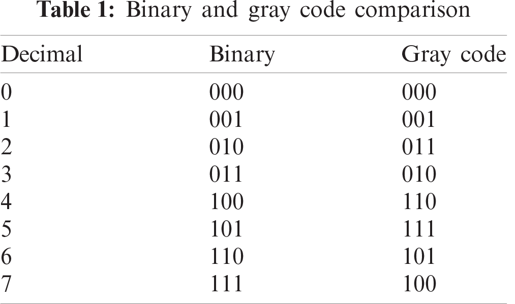
Binary coding is commonly used in structured light, where black is denoted as 0 and white is denoted as 1. In this way, different stripes can be distinguished in the projected image. Gray code is developed from, and more reliable than, binary code [13,14]. Assuming that a binary code can be represented as
Compared with binary code, gray code is advantageous in the aspect that only one code value is different in the corresponding bits between adjacent numbers. As shown in Tab. 1, two bits in the binary code change their values when 1 becomes 2 in decimal; in contrast, only one bit changes in the Gray code. Therefore, Gray code has a certain self-correcting ability in the process of decoding, and correspondingly it has improved error tolerance during coding and decoding.
2.5 Point Cloud Registration and Fusion
In order to reconstruct a complete 3D model, it is necessary to first obtain point clouds from different angles and then splice multiple overlapping point clouds into a complete 3D model through point cloud registration and fusion [15,16]. However, the point cloud data of the object to be constructed are vulnerable to the influences of camera lens distortion, light intensity, and surface texture. Therefore, it is required to first preprocess the point cloud data before registration (e.g. point cloud smoothing and filtering).
Point cloud registration is essentially the process of obtaining the rotation and translation matrices between the source point cloud and the target point cloud.
where
Point cloud registration is generally divided into two categories, namely coarse registration and fine registration. Coarse registration is to find an approximate relationship matrix that can render the target point clouds and source point clouds in the same coordinate system, whereas fine registration is to further optimize the relationship matrix when the initial value is known. In this paper, the SAC-IA algorithm is used for the coarse registration of point clouds [17,18], while the ICP algorithm is used for the precise registration of point clouds [19].
An average fusion method named voxel filtering is used to keep the integrity and smoothness of the point cloud model. Specifically, the object space is divided into many 3D voxel grids with small side lengths, where all points will fall inside. The area with high density has more points in one voxel grid, whereas the area with low density has fewer points in one voxel grid. The side length of the voxel grid can be set to ensure that there is approximately one point inside one voxel grid. The voxel grid is also used for filtering, and the average value of all points in one grid is used as the new point value. This method can not only merge the overlapping areas, but also ensure that the density of the point cloud after fusion tends to be consistent.
The experimental platform consists of a binocular camera with a resolution of
Step 1: Image calibration. The binocular camera calibration algorithm from the OpenCV library is used, and it requires the calibration images to be taken from different angles. A total of 13 images are taken by the left camera to solve the internal and external parameter matrices of the left camera, and the same operation is carried out for the right camera (Fig. 5).
After calibration, the camera parameter matrices
Two images of non-coplanar alignment are corrected to conform to coplanar alignment. Fig. 6 shows the images of the chessboard before and after the correction.
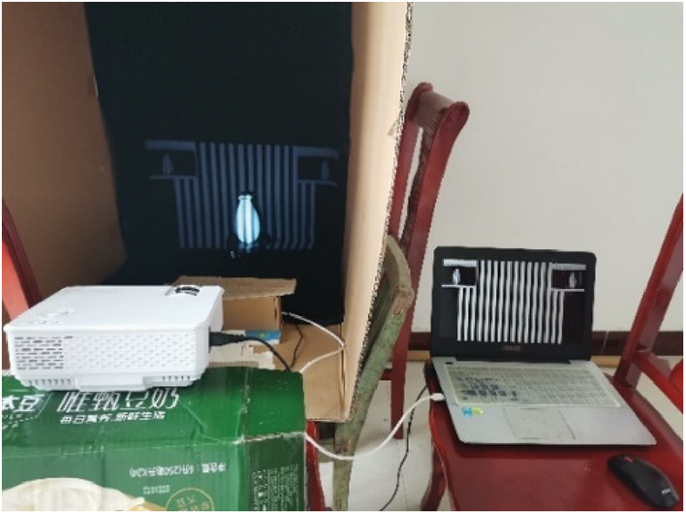
Figure 4: Experiment platform
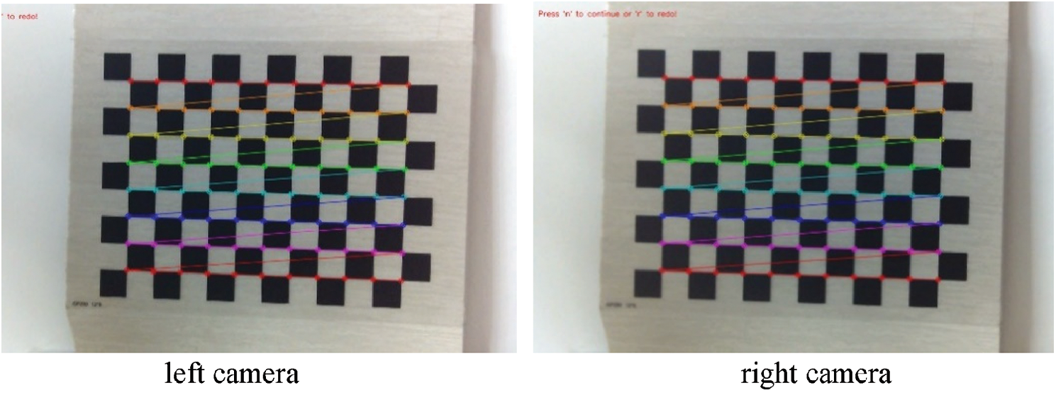
Figure 5: Calibration process diagram of left and right camera
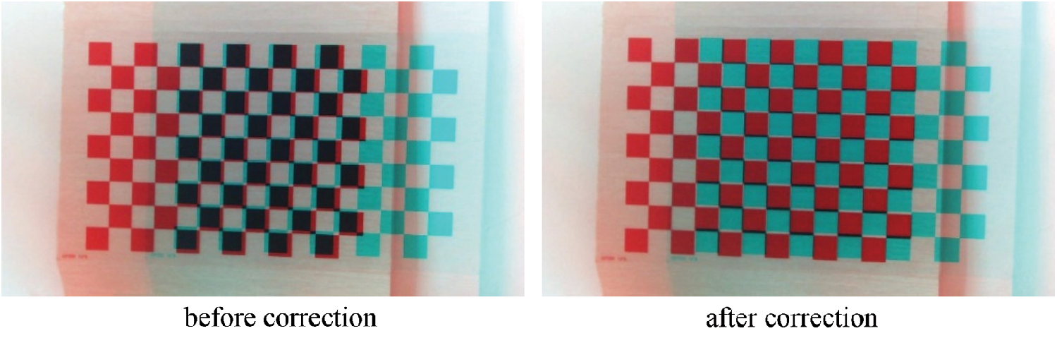
Figure 6: The images of chessboard before and after correction
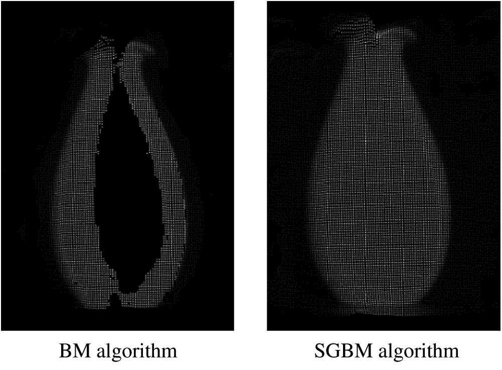
Figure 7: Point cloud maps obtained by BM and SGBM algorithms
Step 2: Image matching. The feature areas of the left and right images are first extracted, and then the polar lines are taken in sequence. For each feature point in the left image, the point on the polar line in the right image that conforms to the given matching threshold is identified as the matching point. The above process is repeated to find all the matching points of the binocular image to obtain a sparse disparity map. The experiment proves that the BM algorithm is favored by rapid image processing, but the accuracy is poor. In contrast, the SGBM algorithm takes a slightly longer time than the BM algorithm, but the accuracy is greatly improved. The disparity map is then transformed into the 3D space, and the point cloud map under one perspective is obtained (Fig. 7).
Step 3: Coding and decoding. A vase is projected by Gray code patterns in vertical and horizontal directions (Fig. 8). It is necessary to first decode the Gray code in two directions separately and then merge the decoded images to obtain a whole image.
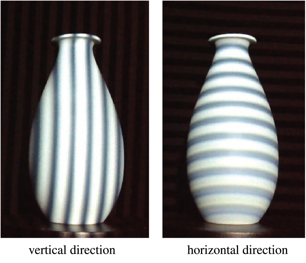
Figure 8: Gray code pattern projected on the vase
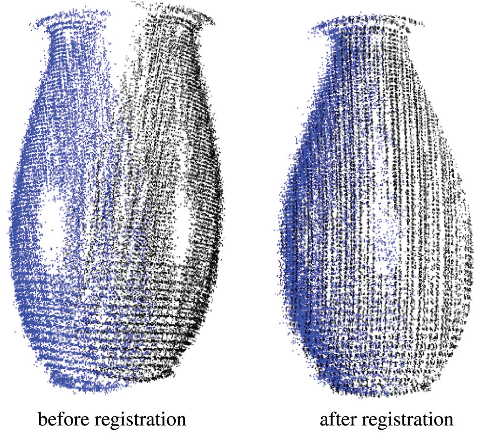
Figure 9: Point cloud image before and after registration
Step 4: Point cloud registration. The decoding results of the left and right images are used to reconstruct the point clouds. The rotating platform is to get the multi-viewpoint clouds. SAC-IA and ICP algorithms are used to register the point cloud data. Fig. 9 shows the point cloud images before and after registration.
Step 5: Point cloud fusion. Since the distance between the camera and the object is almost constant, the density of the object point cloud is basically the same. Therefore, a fixed side length of the voxel grid, which is 1.0 mm, is suitable for all the point clouds in this experiment, with which the obtained 3D point cloud model has a uniform density (Fig. 10).
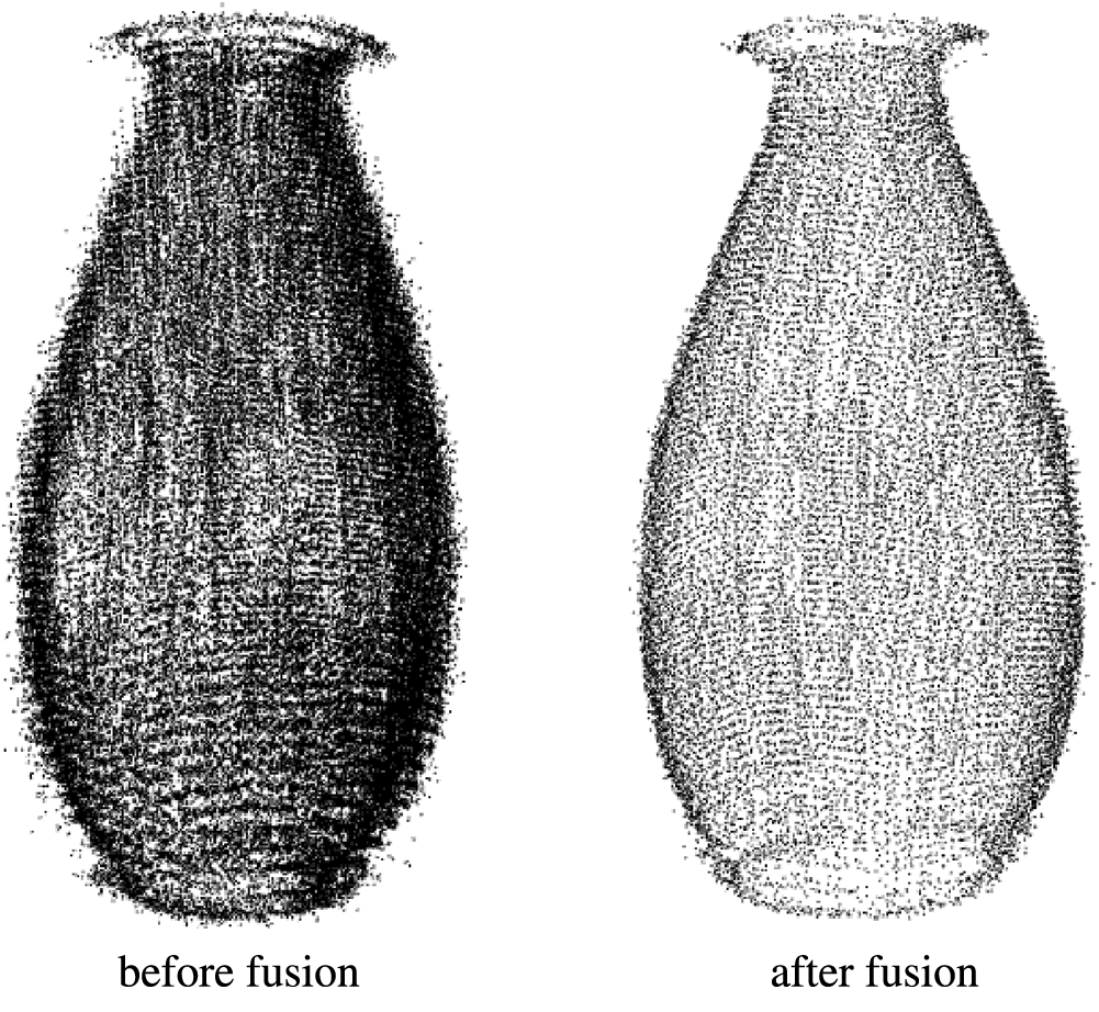
Figure 10: Comparison of point clouds before and after fusion
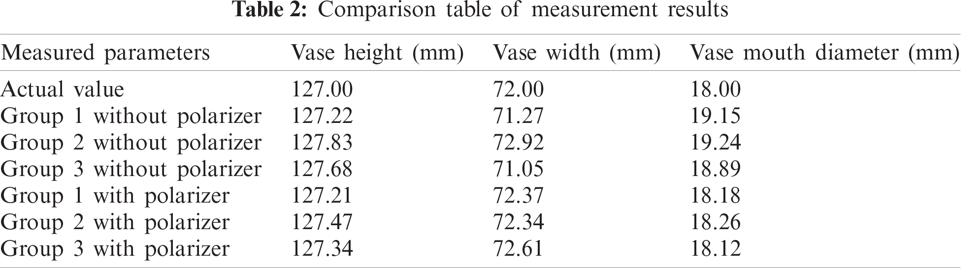
In order to determine the accuracy of the reconstruction, it is necessary to measure the reconstructed 3D model and compare it with the actual vase. A polarizer is mounted in front of the cameras to filter out the redundant reflected light, which can help improve the reconstruction quality. The measurement results of the 3D model are shown in Fig. 11, and the comparison between the model and the actual vase is shown in Tab. 2. In general, the reconstruction errors for vase height and width are less than 1 mm in all groups no matter whether the polarizer is place. However, the placement of the polarizer improves the reconstruction error of the vase mouth from >1 mm to <1 mm. The object reconstruction and measurement accuracy can achieve the millimeter level, which should be improved in the next step.
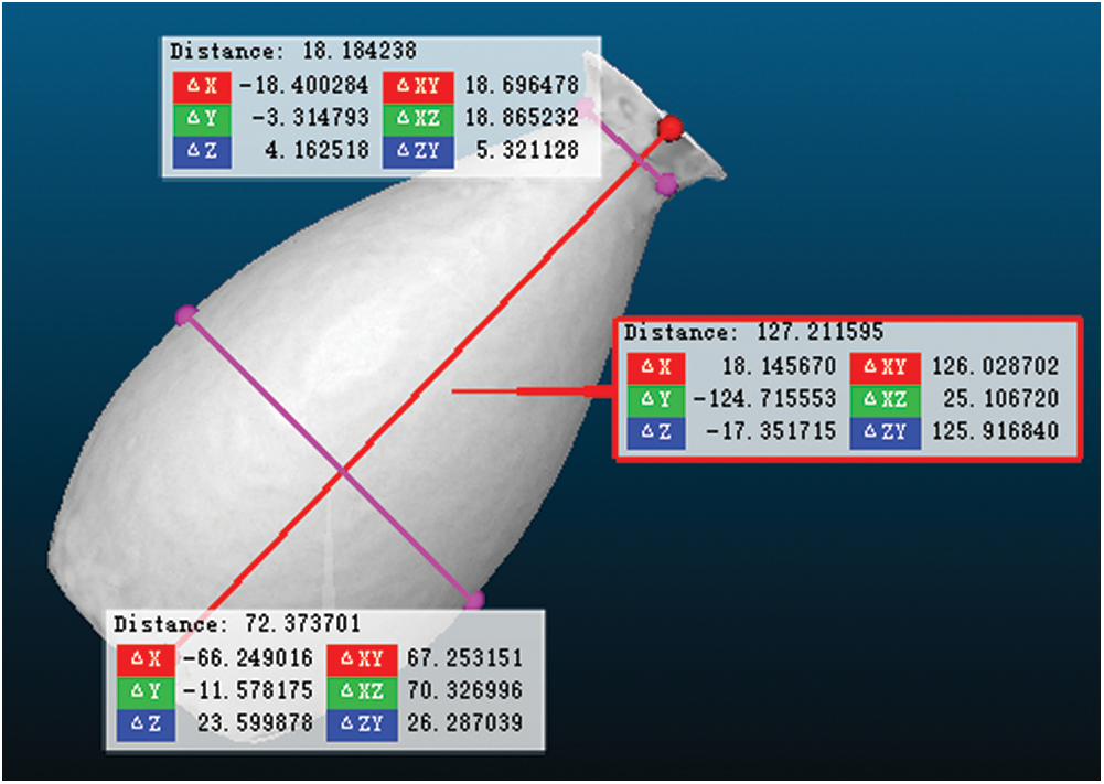
Figure 11: Measurement results of reconstructed vase model
In this study, the principle of the binocular stereo vision is first described, followed by the calibration of the binocular camera, the acquisition of internal and external parameter matrices of the cameras, the generation of the disparity map and point cloud map of the vase based on the stereo matching algorithm, and the investigation into the registration and fusion methods for the point cloud. Experiment results show that the reconstructed 3D model of a vase has a satisfactory performance, which can meet the need for rapid measurement of an object.
Acknowledgement: The authors would like to thank the anonymous reviewers and the editor for the very instructive suggestions that led to the much-improved quality of this paper.
Funding Statement: This work was supported by Henan Province Science and Technology Project under Grant No. 182102210065.
Conflicts of Interest: The authors declare that they have no conflicts of interest to report regarding the present study.
1. S. Gao, “3D reconstruction of small object based on the structured light,” M.S. dissertation, University of Electronic Science and Technology of China, 2019. [Google Scholar]
2. W. Zhu, X. Li and Y. Shon, “Research on clothing simulation design based on three-dimensional image analysis,” Computers, Materials & Continua, vol. 65, no. 1, pp. 945–962, 2020. [Google Scholar]
3. Z. Zhang, P. Li, S. Zhao, Z. Lv, F. Du et al., “An adaptive vision navigation algorithm in agricultural IoT system for smart agricultural robots,” Computers, Materials & Continua, vol. 66, no. 1, pp. 1043–1056, 2021. [Google Scholar]
4. Y. Zhao, J. Fu, H. Yu, J. Han and D. Zhang, “Defocus projection three-dimensional measurement based on deep learning accurate phase acquisition,” Infrared and Laser Engineering, vol. 49, no. 7, pp. 161–168, 2020. [Google Scholar]
5. Z. Cai, X. Liu, X. Peng and B. Gao, “Ray calibration and phase mapping for structured-light-field 3D reconstruction,” Optics Express, vol. 26, no. 6, pp. 75–98, 2018. [Google Scholar]
6. J. Zhang, K. Yu, Z. Wen, X. Qi and A. K. Paul, “3D reconstruction for motion blurred images using deep learning-based intelligent systems,” Computers, Materials & Continua, vol. 66, no. 2, pp. 2087–2104, 2021. [Google Scholar]
7. W. Sun, X. Zhang, X. He, Y. Jin and X. Zhang, “Two-stage vehicle type recognition method combining the most effective Gabor features,” Computers, Materials & Continua, vol. 65, no. 3, pp. 2489–2510, 2020. [Google Scholar]
8. Z. Xiao, W. Zhang, Y. Zhang and M. Fan, “Fatigue investigations on steel pipeline containing 3d coplanar and non-coplanar cracks,” Computers, Materials & Continua, vol. 62, no. 1, pp. 267–280, 2020. [Google Scholar]
9. S. Zhang, “High-speed 3D shape measurement with structured light methods: A review,” Optics & Lasers in Engineering, vol. 10, no. 6, pp. 119–131, 2018. [Google Scholar]
10. J. Hu, F. Zhang, Z. Li and H. Huang, “Research on indoor three dimensional measurement algorithm based on binocular technology,” Computer Measurement and Control, vol. 27, no. 9, pp. 66–70, 2019. [Google Scholar]
11. H. Zhang, L. An, Q. Zhang, Y. Guo, X. Song et al., “SGBM algorithm and BM algorithm analysis and research,” Geomatics and Spatial Information Technology, vol. 39, no. 10, pp. 214–216, 2016. [Google Scholar]
12. T. Li, F. Hu and Z. Geng, “Structured-light 3D surface imaging technology,” Journal of Network New Media, vol. 1, no. 1, pp. 22–33, 2012. [Google Scholar]
13. J. Geng, “Structured-light 3D surface imaging: A tutorial,” Advances in Optics & Photonics, vol. 3, no. 2, pp. 128–160, 2011. [Google Scholar]
14. K. Herakleous and C. Poullis, “3Dunderworld-sls: An open-source structured-light scanning system for rapid geometry acquisition,” 2014. [Online]. Available: https://arxiv.org/abs/1406.6595. [Google Scholar]
15. F. Zhao, M. Zhou and J. Wang, “Point cloud registration algorithm based on probability iterative closest point,” Computer & Digital Engineering, vol. 45, no. 3, pp. 419–422, 2017. [Google Scholar]
16. H. Chen, X. Zhang, S. Du and N. Zheng, “A correntropy-based affine iterative closest point algorithm for robust point set registration,” IEEE Journal of Automatica Sinica, vol. 6, no. 4, pp. 981–991, 2019. [Google Scholar]
17. R. B. Rusu, N. Blodow and M. Beetz, “Fast point feature histograms (FPFH) for 3D registration,” in Proc. ICRA, Kobe, Japan, pp. 1050–4729, 2009. [Google Scholar]
18. R. B. Rusu and S. Cousins, “3D is here: Point cloud library (PCL),” in Proc. ICRA, Shanghai, China, pp. 427–436, 2011. [Google Scholar]
19. H. Zhang, G. Kang, Q. Zhang, W. Zhang and W. Xu, “Laser point cloud coarse registration based on improved SAC-IA algorithm,” Aerospace Control, vol. 37, no. 5, pp. 67–74, 2019. [Google Scholar]
 | This work is licensed under a Creative Commons Attribution 4.0 International License, which permits unrestricted use, distribution, and reproduction in any medium, provided the original work is properly cited. |