DOI:10.32604/cmc.2021.017773
| Computers, Materials & Continua DOI:10.32604/cmc.2021.017773 | |
| Article |
Complex Problems Solution as a Service Based on Predictive Optimization and Tasks Orchestration in Smart Cities
1Department of IT Convergence Engineering, Gachon University, Sujeong-Gu, Seongnam-Si, Gyeonggi-Do, 461-701, Korea
2Department of Computer Engineering, and Department of AI Convergence Network, Ajou University, Suwon, Korea
3Computer Engineering Department, Jeju National University, Jeju, 63243, Korea
**Corresponding Author: DoHyeun Kim. Email: kimdh@jejunu.ac.kr
Received: 10 February 2021; Accepted: 03 April 2021
Abstract: Smart cities have different contradicting goals having no apparent solution. The selection of the appropriate solution, which is considered the best compromise among the candidates, is known as complex problem-solving. Smart city administrators face different problems of complex nature, such as optimal energy trading in microgrids and optimal comfort index in smart homes, to mention a few. This paper proposes a novel architecture to offer complex problem solutions as a service (CPSaaS) based on predictive model optimization and optimal task orchestration to offer solutions to different problems in a smart city. Predictive model optimization uses a machine learning module and optimization objective to compute the given problem's solutions. The task orchestration module helps decompose the complex problem in small tasks and deploy them on real-world physical sensors and actuators. The proposed architecture is hierarchical and modular, making it robust against faults and easy to maintain. The proposed architecture's evaluation results highlight its strengths in fault tolerance, accuracy, and processing speed.
Keywords: Internet of things; complex problem solving; task modeling; embedded IoT systems; predictive optimization; artificial cognition; task orchestration
The unprecedented plethora of miniatured sensing devices has shown a remarkable breadth of smart city vision. Internet of things (IoT) has always been among the leading technologies for the realization of smart cities transformation initiatives [1–5]. Be it a smart home, smart healthcare, or a smart grid; the IoT has genuinely made these things possible in real-time, even if the users are not on-premises [6]. Over the past few years, IoT architecture has been based on the cloud. The context data sensed from sensors were stored in the cloud to process and apply intelligence. However, with the evolution of technology, and the ever-growing demand for time-sensitive services, edge nodes were introduced to move the application closer to boost speed. The use of such distributed edge nodes offered several advantages in terms of timeliness and safety [7,8].
Nevertheless, smart cities are defined subjectively, and consequently, there is no universally accepted definition. However, the agreed fact among them is smart services’ provisions by exploiting IoT technologies to bring value to human lives. Smart services demand the processing of massive context information in real-time to make informed decisions from the set of different alternatives. Such decisions usually involve optimizing and selecting the best compromise among the possible choices, often termed as complex problem solving (CPS). A problem is categorized as a complex problem if the solution depends on more than two contradicting parameters [9]. Smart services development involves complex problem solving as there is no exact optimal point, and also, the dependent parameters are many in numbers. In other words, to develop a smart service, there should be a systematic approach or generic template for complex problems accurately and efficiently, considering learning from previous statistics of incidents and forecasting similar situations in the future. Different state-of-the-art methods witness approaching complex problem solutions. Still, the problem is that the solution was based on a single problem with different contradicting solutions and based on human.
Consequently, approaching solutions to a complex problem with more than one parameter is still a gap in the state-of-the-art, which has led to the work presented in this article. This paper proposes novel architecture names as CPSaaS to allow smart city citizens and administrators to model their problems and get the solution as a service. The architecture uses a distributed edge computing paradigm to faster processing massive context data. The solution is based on optimization and learning modules, which consume the dataset and real data coming from sensing nodes to make optimal decisions. The second module of the architecture relevant to the smart service's efficient delivery is the task orchestration module. Recent IoT architectures have introduced the concept of task-based orchestration in contrast to conventional service-based orchestration, which is flexible, scalable, and has a much faster response time. Therefore, the architecture is based on predictive optimization (Solution composition) and task orchestration (Solution deployment) to offer smart city services on demand.
The proposed architecture's ultimate goal is to provide a generic open-source, highly-cohesive and loosely-coupled modular architecture that includes optimization, control, prediction, and scheduling algorithms in its core. The architecture aims to be an edge-compliant system. The different services and microservices are deployed in the edge computing environment to support applications’ real-time compliance. In other words, the architecture will serve as a barebone platform for implementing different smart services related to smart cities transformation, such as smart homes, smart farms, and smart grid.
The main contributions of this paper are as follows:
(a) To propose a novel architecture based on predictive optimization and task orchestration mechanism to offer smart cities’ complex problem solutions as a service.
(b) To implement a generic prototype of the architecture and improve it by other researchers.
(c) To illustrate this architecture's significance by solving different cases using various proposed architecture modules.
The rest of the paper is organized as follows; Section 2 highlights the state-of-the-art relevance to this work; Section 3 presents the system's general model. Section 4 presents the objective formulation for different optimization problems. Section 5 covers the architecture's implementation and highlights the system's execution with different modules’ snapshots. Section 6 presents the system's performance comparisons with different measures, and Section 6 concludes the work and highlights future directions.
Smart city transformation ventures involve a massive number of complex problems and how to approach them to get a feasible and optimal solution, among other alternatives. Such complex systems require an intelligent mechanism to utilize current state-of-the-art methods in machine learning and optimization. CPS has been started to plan how to approach the solution. Planning is vital and has been witnessed in many studies. Some of the research questions plan the planning interval's length related to CPS performance. For instance, the authors in [10] emphasize on the role of planning and model planning as a performance measure. The authors also demonstrate that the categorization of different complex problems and their categories in terms of solution approaches and determine the complexity of low-complexity, medium-complexity, and high complexity. It has been suggested in the paper that the higher number of inputs and the higher complexity, the more challenging the solution is. The authors in the same study have also given a proposal about the multiple complex systems (MCS) approach for assessing domain-general CPS skills and its processes knowledge acquisition and knowledge application has been highlighted. After defining the construct and the formal frameworks for describing complex problems, it has been emphasized that some of the measurement issues inherent in assessing CPS skills with single tasks (i.e., fixed item difficulty, low or unknown reliability, and a significant impact of random errors).
The time, the variation, and interaction effects between different solutions are also a significant area studied in various literature studies. The authors in [11] investigated the planning activities in the process of complex problem solving and operationalized planning through three behavioral measures indicating the duration of the most prolonged planning interval, the delay of the most prolonged planning interval, and the variance of intervals between every two successive interactions.
With advancements in IoT, the massive volumes of data generated from IoT devices revamp the core CPS domain. As a result, numerous recent studies highlighted the data's involvement in complex problem solutions in addition to the planning stage. The statistical analysis of the complex problem-solving process data can also lead to different patterns corresponding to the individual's ability to approach the problem. For instance, the authors in [12] considered the prediction of duration and outcome (i.e., success/failure) of solving a complex problem during the task completion process using process data recorded in computer log files. The trained prediction model may provide a better understanding of individuals’ problem-solving patterns, which may lead to an excellent automated design. The proposed study attempted to solve the questions such as How much additional time the individual needs and whether the individual will succeed or fail upon task completion.
Nevertheless, modern technologies’ evolution has changed the original face of complex problem solutions. For instance, in the studies above, the solution to complex problems was purely based on human-based cognition, and the psychology of human minds was part of the solution process. However, with the advances in IoT and machine learning technologies, the solution can be purely based on artificial cognitive techniques. Various modern studies related to the IoT and complex problem solving are carried out to find optimal solutions in a smart city's services. Different studies’ critical ideas decompose a complex problem into different small problems. For instance, in [13], to solve complex information problems, the authors first need to transform and map it into simpler connected problem components that different IoT architecture layers can address. This approach is very similar to the Fourier transform, where a complex signal is first distilled into its base frequencies in the frequency domain. Later, a linear multistage solution is developed to address these individual frequencies as desired. Some frequencies are amplified, some are attenuated, and others are altogether eliminated. This solution is then transformed back to the original domain and implemented with physical components. A similar approach can be applied to business problems by transforming the information domain and solving them using IoT architecture.
The concept of a task is very crucial in CPS. The task orchestration concept of IoT can be leveraged in this domain to benefit flexibility inherent in task-based composition rather than service-based composition [14,15]. When it comes to task-based deployment rather than service-based deployment, the term task orchestration often pops up in contrast to the famous service orchestration. The service-based composition is prevalent in service-oriented architecture [16–17]; however, it suffers from the challenge of changing the core even if a small change is made from users [18–19]. In other words, the service-based composition is not flexible in cases where the architecture is prone to frequent changes.
3 Design Architecture of Proposed CPSaaS
Smart cities service consists of one or many complex problems. Every problem, in turn, has many micro-problems. A micro-problem is represented with different functional units known as tasks. A task can have a defined goal and potential barriers towards achieving a particular purpose. The task generator module generates tasks and applies a series of operations, which is part of building the solutions. The tasks are once generated, stored in the repository. The tasks are then mapped on virtual objects.
The hierarchical model of the CPSaaS is portrayed in Fig. 1. The complex problem (part or whole of the smart service) has different micro-problems, and each problem has different goals. Every goal can be achieved with a set of tasks. The tasks have methods and corresponding devices on which they should be executed. Once the tasks are generated, the appropriate task data is used to run the prediction algorithm and find the target features. For instance, in a microgrid, the output features could be demand prediction, load prediction, and renewable energy prediction, to name a few. The output features are used to find the optimal values of tasks, and during the course, some tasks which are not optimal are discarded. The optimal tasks are mapped on virtual objects using virtualization technologies adopted from different literature works [15]. The tasks are then scheduled to find the optimal ordering in time. The control algorithm is run to find the operation duration of physical devices to prevent them from over-using the devices. Finally, the tasks are allocated using function data and URI to the corresponding grid devices.
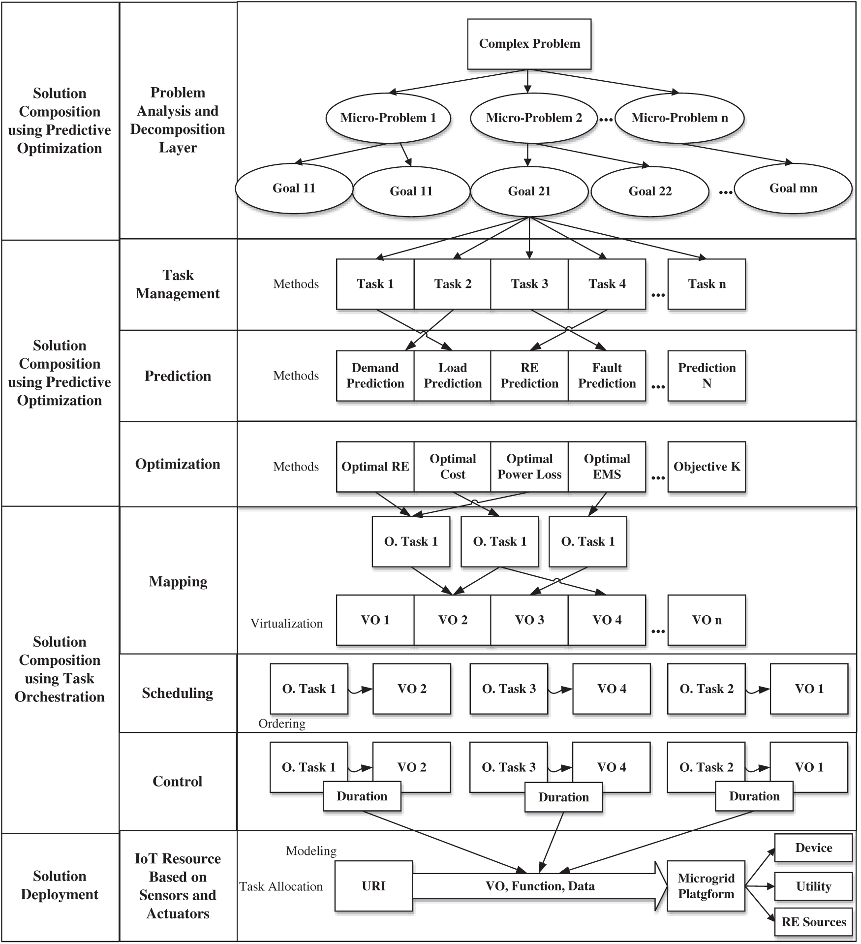
Figure 1: Hierarchical CPS layered architecture
3.1 Design of Task Orchestration for Smart Service Delivery
The first module is problem analysis and decomposition. The problem analysis and decomposition constitute a process of analyzing the input problem's description and automatically generating micro-problems and complex tasks. The problem's description is analyzed using text mining techniques to extract tokens that seemingly indicate a functional unit of the problem. The functional unit can be atomic or composite. If it is composite, the system generates a micro-problem for it. In contrast, in the later case, a complex task is generated to indicate an atomic functional unit of the complex problem.
The mapping process is a multi-level process. In the first layer, the micro-problems and solvers are supplied to the mapping plane. The mapping plane contains candidate solver objects (SO), candidate micro-problem (mp), and different types of solvers, such as state-of-the-art algorithms. The mapping consensus can be manual or semi-autonomous. In the semi-autonomous approach, the best solver is computed based on different correlative analyses. In contrast, in the manual method, the micro-problems are manually dragged on the solver to map them and save them in the repository.
Once the mapping is performed, the optimal tasks are selected, relevant to the problem and solver mapping pair. The optimal tasks and virtual objects are applied to the next level of the mapping plane. In this level, tasks are mapped on virtual objects. At this level, the consensus algorithm is also similar and can be manual or semi-autonomous. The mapping algorithm is a task, virtual object (task, VO) pair stored in the repository, later to be used by the scheduling solvers and the control solvers. Algorithm 1 shows the multi-level mapping process.
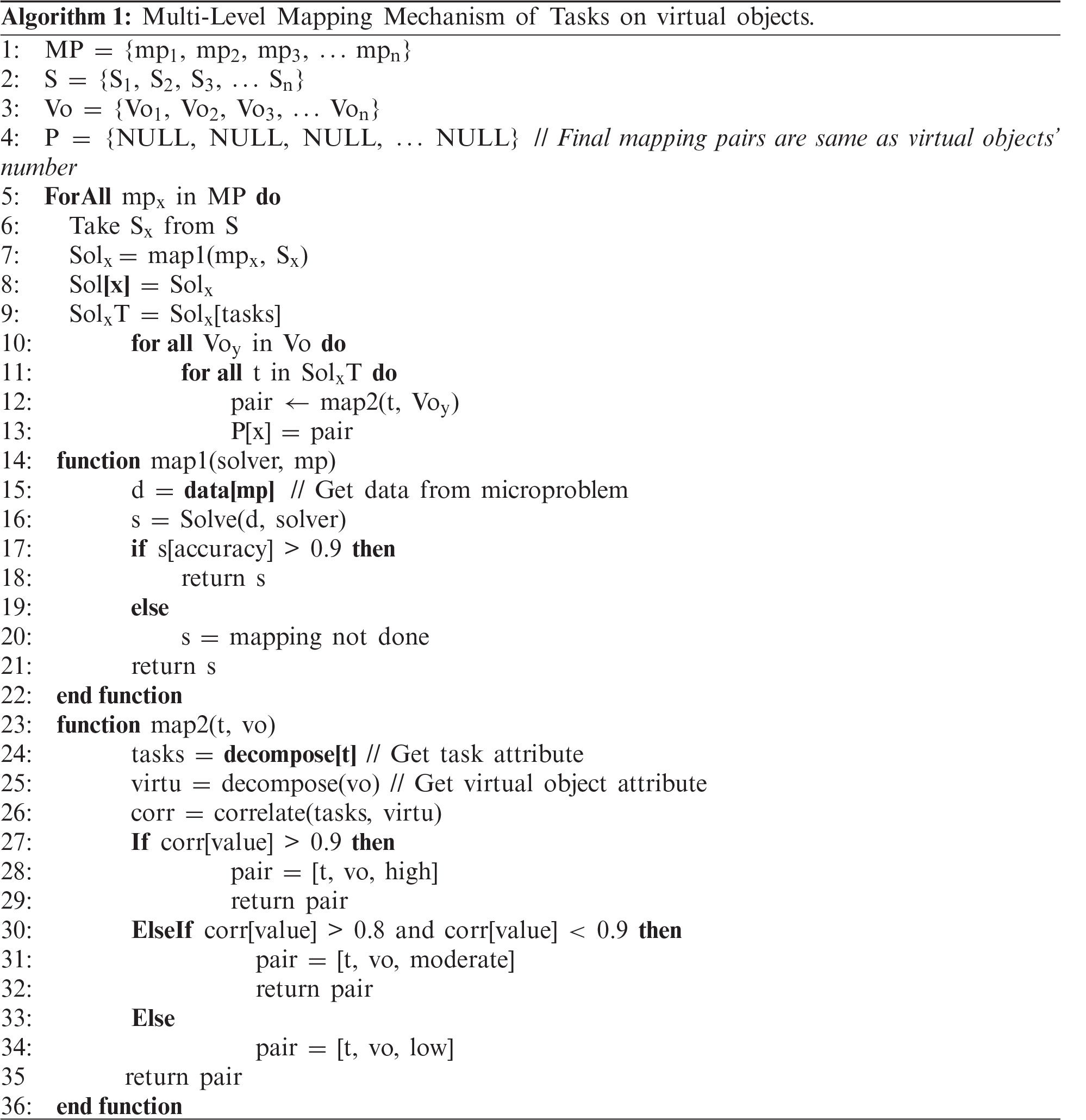
Initially, the mps are mapped on solvers to find a solution of appropriate quality. Once the solution is found, the solution's optimal tasks are mapped on virtual objects in the second phase. In the second phase, the mapping return task-object pair and the quality of the mapping as high, medium and low depend on the correlation of tasks with different virtual objects attributes.
3.2 Predictive Optimization in Hierarchical CPS Architecture
The core functionality of the smart city service implementation is to make informed and optimal decisions. In this regard, CPSaaS architecture solves problems based on a novel predictive optimization mechanism. A prediction problem refers to the behavior of a certain parameter in terms of the future. A prediction problem can also be considered a complex problem if the prediction problem's nature is unknown and the problem has many contradicting solutions. In this work, a prediction problem can be assigned different prediction solvers based on the data analysis. The solver can make a solution that can be feasible or not. The proposed architecture also provides the efficacy of the solver and the quality of the solution.
Optimization is another central module of the core solutions which the proposed architecture provides. Optimization is the selection of optimal design values based on the input design parameters subjected to a set of constraints. The optimization process can be as simple as finding the minima of a linear function or can be as daunting as searching a massive set of values to find the minima and maxima of a higher-order cost function. In this architecture, the goal is to analyze the problem that has to be optimized, find the relevant category of optimization solvers, and optimize it to get the optimal design parameters’ optimal values. These modules work in conjunction by propagating different parameters, as shown in Fig. 2. The learning module provides model parameters, such as weight in the ANN case, and the optimization module finds optimal solutions based on the current data and the model keeping constraints and user requirements.
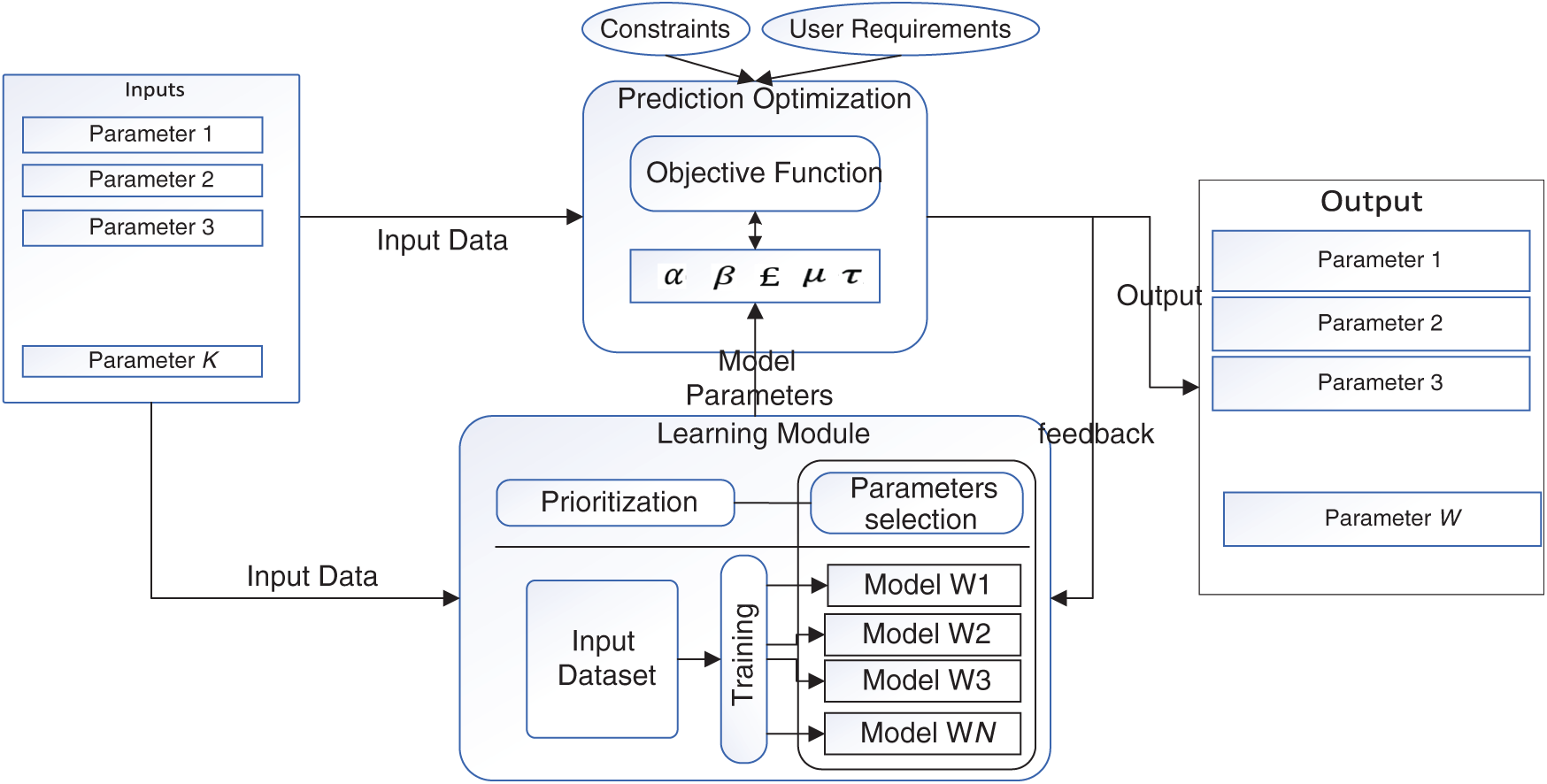
Figure 2: Block diagram of predictive optimization
4 Implementation of CPSaaS Architecture
In this section, we will discuss the implementation and the execution results of the proposed architecture. First off, a summary of the tools and technologies, which have been used to implement this work has been illustrated. The project has different modules, either of which has a specific goal. There are three types of work in this project. First, the interface development, second, the visual effects and last is the backend persistence. The implementation tools and technologies for either of these modules are given in Tab. 1.
Table 1: Implementation technology stack of proposed CPS
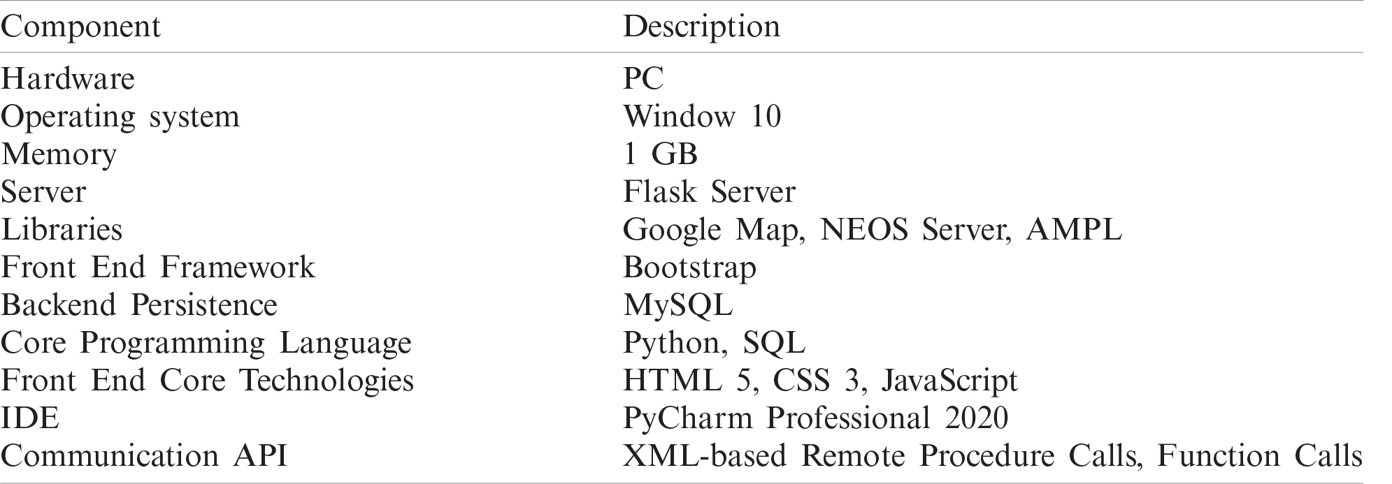
Overall, we have used Python as a core programming language, MySQL as a database for persistence, and HTML 5, CSS3, and JavaScript for front-end work. On top of these core technologies, we have utilized a different framework that facilitates the job of development and ensures best practices in the code and design.
We used flask, a mini and lightweight python-based framework based on a popular model-view-control (MVC) architecture. Flask is a compelling framework considering its modular architecture lazy-loading capabilities of different modules on-demand, making the core of the barebone framework very lightweight. For visualization, we used Bootstrap 3, which provides a set of CSS-based design widgets and JavaScript-based animation. Bootstrap makes front-end development very fast and organized. For templating, the view part of MVC, we have utilized the default template engine Jinja which is shipped with Flask core. Different add-on and libraries, such as Google MAPS API, AMPL, NEOS-Server API, and JSPlumb have been utilized to perform different tasks towards the goal. For instance, Google maps provide the visualization of devices; AMPL translates objective function from database to AMPL format, which is then inputted to NEOS-Server in XML. Lastly, JSPlumb is a JavaScript-based library that allows the architecture users to design the problem in a design plan and map different tasks.
While modeling a solution for a given problem, the first step is the problem analysis phase. The description of the problem is analyzed to automatically generates micro-problems and complex tasks using basic NLP algorithms. The next step is the addition of complex tasks and micro-problem persistence. One they are persisted; they are populated from the database to be used in the design of the solution process. The solution composition responsible for composing solutions, in turn, has different sub-modules. A Solution is composed using different solvers, and the problem is mapped on different solvers based on drag-and-drop features. The drag-and-drop performs the following operation; Prediction Mapping: Prediction Mapping is mapping micro-problem with a prediction algorithm. The optimization mapping is a process of mapping of problem to the objective functions and, in turn, mapping it on the candidate solvers towards building a solution. Task mapping is mapping optimal tasks on virtual objects that will be eventually used to deploy a solution on physical devices. Scheduling and control mapping select the scheduling solvers and control solvers for the optimal tasks-virtual object pairs.
Once the solution is composed, it is persisted in the database. The view solution page has the option to deploy the solution and generates results. Apart from it, different administrator jobs include adding objective functions, solvers, virtual objects, and devices to the system. For each project, there are specific problems and specific tasks which can be changed per-project basis.
For instance, the automatic generation of complex tasks and micro-problems based on problem description is given below:
• Name: Smart Grid Management
• Description: The main goal of this problem is to compute cost and optimize input parameters. The wind sensor, solar sensor, and load sensor are received and processed to calculate cost. If the optimal cost is predicted, the optimal parameters are sent in the form of lights and voice to take the action
The resultant micro-problems and complex tasks are generated based on text mining and pattern analysis techniques. The generated tasks are shown in Fig. 3. These tasks can be added to the repository or discarded if they do not match well with the problem's requirement. The repositories of problems and micro-problems are shown in the lower part of Fig. 3.
In this section, the solution modeling is illustrated in detail. The modeling of the solution is considered a prerequisite to the solution composition. In solution modeling, the components participating in the solution composition process are provided to the architecture. These components include solvers, objective functions, prediction data, optimization data, to name a few.
Once these components are added to the system, the next phase is to populate these components to compose a solution.
In Fig. 4, the add solver web form in the left allows the user to add a specific solver. The solver is of four types; Prediction solver, optimization solver, scheduling solver, and control solver. The hyperparameters are additional parameters that are necessary for running the solver to get the results. For instance, for ANN, the hyperparameters are the number of hidden layers, number of input, number of output, and optimizer, to name a few. The hyperparameter can be added in each line in the form of parameter|value. Once the form is submitted, the solver is persisted in the solver repository, as shown in Fig. 4. If the solver type is optimization, then it requires an additional component which is the cost function or the objective function. The objective function is the quantitative measure of the goal which the optimization solver aims to achieve. For instance, if the optimization solver seeks to minimize the cost, then the objective functions a function that computes the cost. The objective function consists of three parts; design variables, cost function, and constraints. The system takes the objective in a well-documented form that must be given in the same form to be consumed by the optimization solver. For example, the energy price in the nighttime is very high due to heavy load. In the daytime, it is not high, so to optimize the energy consumption for minimizing the cost function, the following objective function can be used.
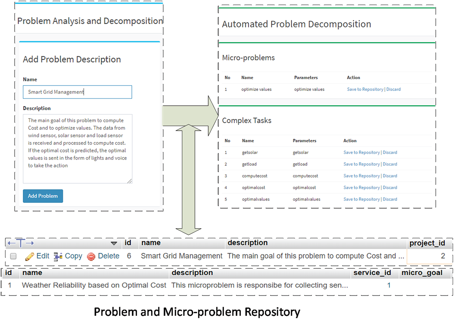
Figure 3: Problem description and decomposition into micro-problems and complex tasks
min cost = 5dt ∗ enr + 7.5nt ∗ enr
subject to
dt + nt ≤24
5dt ∗ enr + 7.5nt ∗ enr ≥ 200
In this objective function, the design variables are dt which is the daytime usage duration, enr which is the energy consumption rate per hour, and nt which is the nighttime energy usage duration. We provide the design variables as follows
name|value
dt|0
nt|0
enr|20
Similarly, the cost function will be given as it is in the cost field. The constraints should be provided in pair of three constraint|operator|value, e.g.,
dt + nt|le|24
5dt ∗ enr + 7.5nt ∗ enr|ge|200
One of the most important modules of this architecture is the composition of the solution using a DIY plane. In this plane, the solution components and the problems are populated. There are four distinct sections on this page; solver mapping, task mapping, scheduling mapping, and control mapping. Solver mapping has two different sub-modules; prediction mapping and optimization mapping.

Figure 4: Solver and management and persistence mechanism
The plane uses a JavaScript-based library named as JSPlumb. JSPlumb facilitates non-technical users to compose solutions based on their requirements without doing any coding stuff. For this, JSPlumb supports drag and drop features, allowing users to connect one component of the solution with another. Usually, there are micro-problems which has a distinct goal. The micro-problem is connected to the prediction goal and then the prediction solver to make a prediction solution-line. The first and foremost thing is the prediction and optimization solution line. For every micro-problem, two things have been performed—first, the composition of the prediction solution line, and second the composition of the optimization solution line. In the prediction solution line, a micro-problem is mapped on its prediction objective, and then a suitable algorithm is assigned to achieve the goal. For instance, for the weather reliability problem in micro-grids, energy forecasting is essential to make informed decisions in the future. For this, the energy prediction goal is mapped on the ANN solver. So, the first solution line in the solution repository corresponds to this configuration.
Secondly, after prediction composition, optimization composition is performed. In optimization composition, the problem is mapped on the objective function and, in turn, on the optimization solver. For instance, the weather reliability problem in micro-grid energy consumption should be optimized so that renewable energy is used the maximum amount of the time and a minimal amount of non-renewable energy is used considering there is a need from the utility. Therefore, the problem is mapped on the energy consumption objective function and the genetic algorithm in this solution line.
Once the solution line for optimization is persisted in the solver repository, it can be retrieved in the solution deployment space to allow their deployment. In Fig. 5, the contribution of different repositories in making the solution line has also been illustrated. For instance, in the prediction solution line, the dataset repository, prediction objective, solver repository, micro-problems repository, and problems repository take part in the optimization solution line. The objective function repository solver repository, dataset repository, micro-problem, and the problem are depicted in Fig. 5.
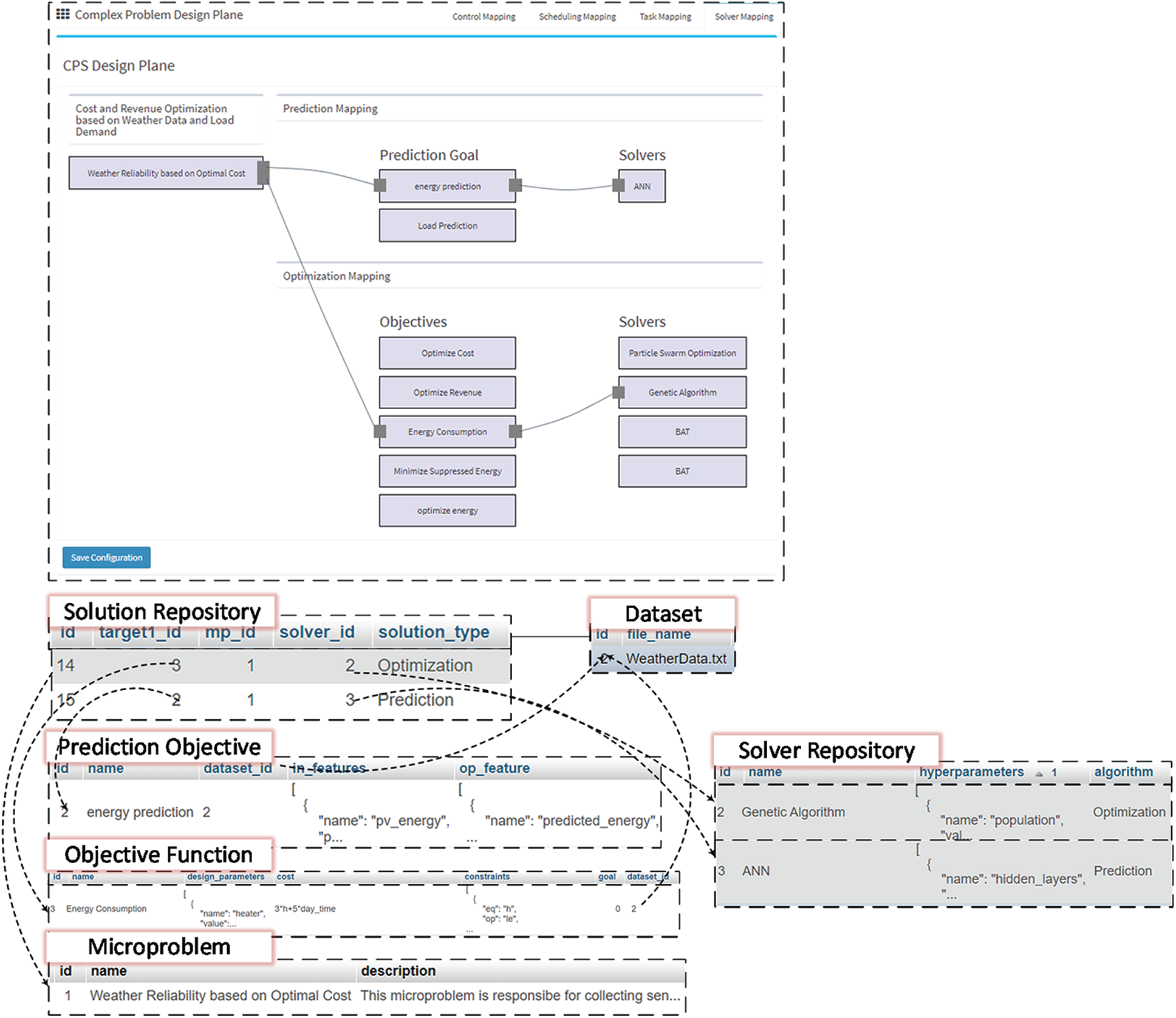
Figure 5: Solution configuration and persistence post solution mapping
In deploying the optimization solution, we use an optimization solver hosted on NEOS Server. It is a host of different variety of optimization solvers of different optimization categories. NEOS server accepts optimization command in various input formats, such as AMPL, Julia, to name a few. In this work, we use AMPL as an input type. Similarly, to interact with the NEOS solver, an API call must be made. RESTful API, XML-RPC is among the notable communication protocol. We use XML-RPC, as it is the stable version that the latter and supports more solvers. Fig. 6 shows the flow of operation of deploying the solution on the NEOS Server. The flow is as follows:
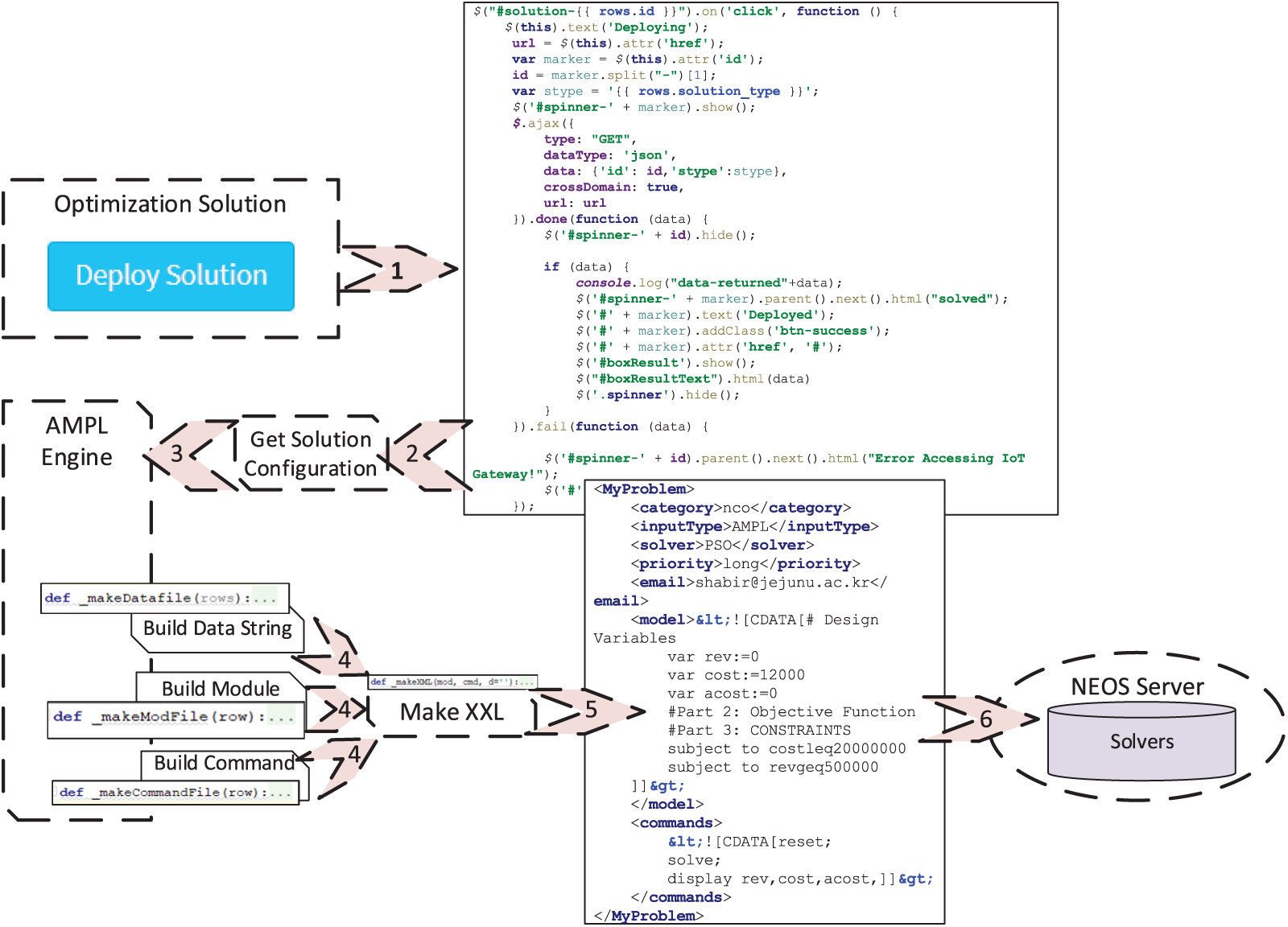
Figure 6: Optimization solution deployment and API request to NEOS server
A deploy solution button is clicked on the architecture-end (client), which triggers an ajax request. The ajax request calls an endpoint on the client application, which gets the solution configuration data from the solution repository. The solution configuration is provided to the AMPL engine module, a custom module written to convert the user-provided objective function to AMPL format.
The AMPL engine provides three types of string named module string, data string, and command string and given to the MakeXML module. The MakeXML module takes the input string and converts it into an XML string. The XML string is finally provided as a parameter in the XML-RPC call. The command is executed using the solver and category provided in the XML and gives back the client's result.
Once the solution is deployed, the solver used in the solution configuration file gets results, and the architecture visualizes the results. For instance, in the prediction of load projection, the solver gets results and shows them in graphical form on the solution page. The process for the optimization solver is also similar. The optimal values instead of prediction are returned to the CPS architecture from the NEOS Server. Fig. 7 portrays the resultant interface for a sample problem titled “Load Projection.” The first box shows the solution configuration and the button to deploy it, while the subsequent boxes visualize resultant output parameters and highlight the solution's quality.
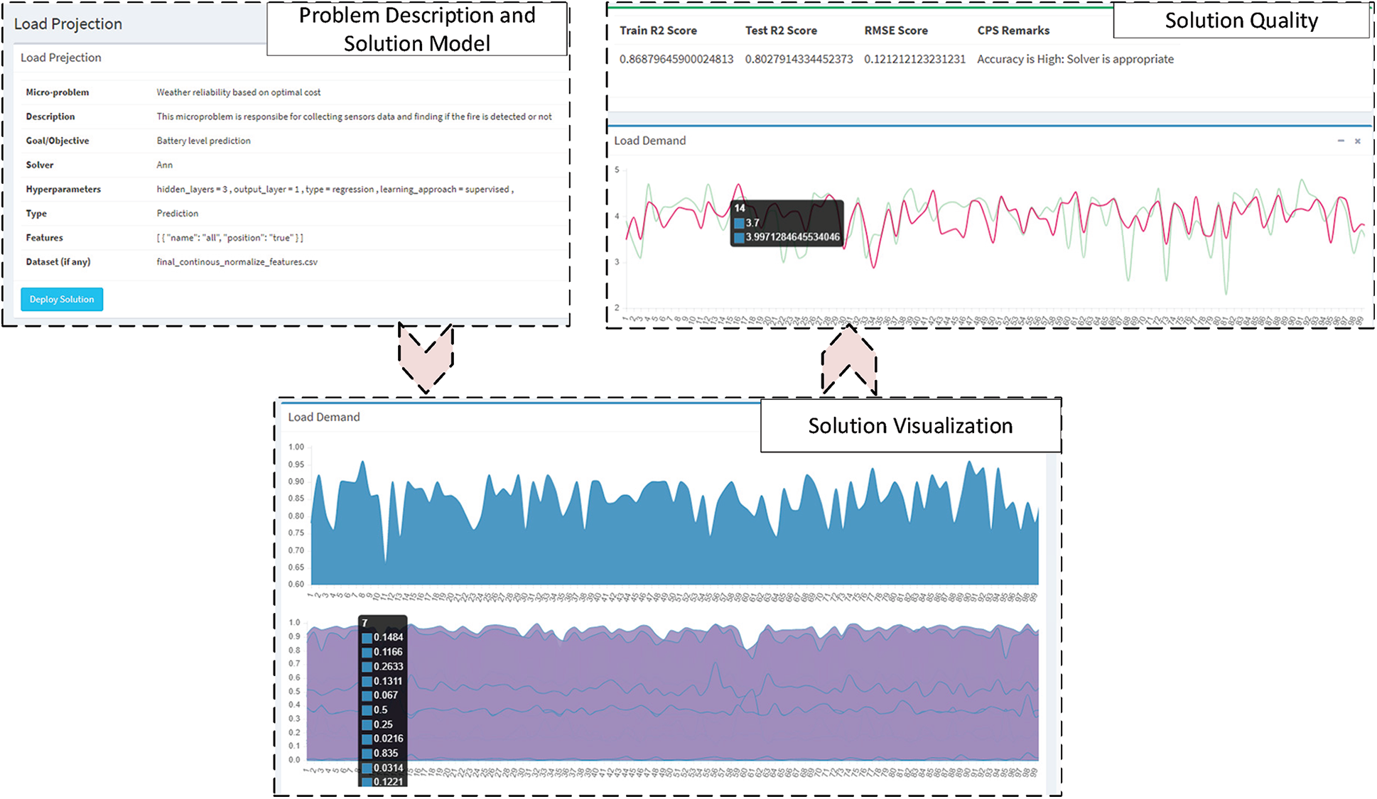
Figure 7: Prediction result based on MLP regressor for an example problem
One of the crucial measures for the robustness of architecture is its response towards the fault. A system is said to be fault-tolerant if it degrades gracefully. In IoT applications, it has become even more critical due to the un-reliable nature of communication media and end devices. Our proposed architecture has a fault management module based on the mechanism employed in [11] to support graceful degradation if a node is not reachable at some point. The mapping mechanism in each step has been made so that it maps one to 5. The five suggested items are next in the line. For instance, if a problem is mapped on a single solver, then the next 5 solvers are being placed in the queue. In case the suggested solver is not accessible on the NEOS server, the next solver is fetched from the queue, and the request is made accordingly. Initially, the mapper algorithm runs to select the top 6 recommended devices for the tasks. The task is deployed on the first one, and if the device is not accessible, it pops the next from the queue. The process goes on if the next device is also not reachable, and this goes on until the queue eventually gets empty.
In the worst case, the algorithm runs again for the mapper to generate the following 6 devices and stores them in the queue. Based on the above mechanism, 100 tasks are generated with a random induction of fault. The best device for a task considers the network latency, pair compatibility, and surplus time among the few. Therefore, the response time for the first pair is the fastest. The next has a little slower response, and so on. In the worst-case scenario, where there are no active nodes in the queue, a mapper algorithm is a re-run to get the updated list of devices. In this case, the response time has the added latency of the mapper algorithm time, and thus a peak is observed each time the queue gets empty, as shown in Fig. 8a. The response time deviation is shown in Fig. 8b is also proportional to the number of failed nodes. The deviation in modulo 5 is more due to the mapping algorithm overhead. The trend shows that the recovery time is estimated as considering
The architecture is scalable if the response time of the page load is not degraded in peak load. As the proposed architecture is web-based, we have used Apache JMeter to create automated test scripts and then imported the code into Blazemeter software.
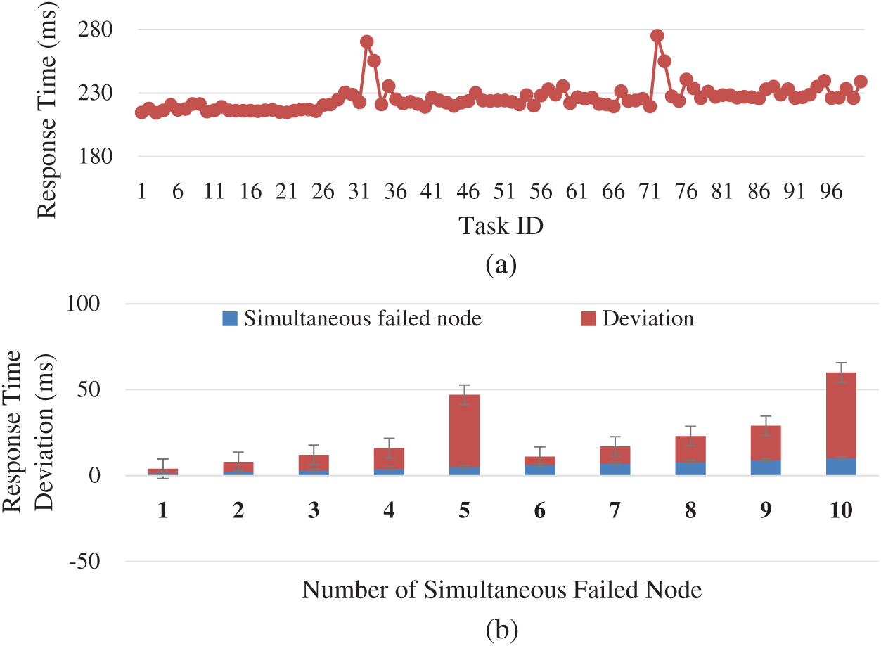
Figure 8: Fault tolerance and response time (a) Failure effect on response time (b) Response time deviation
We recorded different endpoints in the web-application and simulated it for 50 simultaneous virtual users with 100 ms granularity, as shown in Fig. 9. The throughput of pages related to three different modules of the architecture is recorded. From the throughput and the response time over a graph, it has been shown that the modeling phase has the fastest response time, highest throughput, solution composition being second while the deployment has the slowest response time, and as a result, the throughput is also relatively low. The main reason for this trend is the functionality inherent in these modules. Modeling the solution involves merely a single insert query; the solution's composition involves joins of tables and a relatively more significant number of queries, making it a little slower. Finally, the solution deployment has a dependency on 3rd party applications and libraries, so it has the slowest response over time.
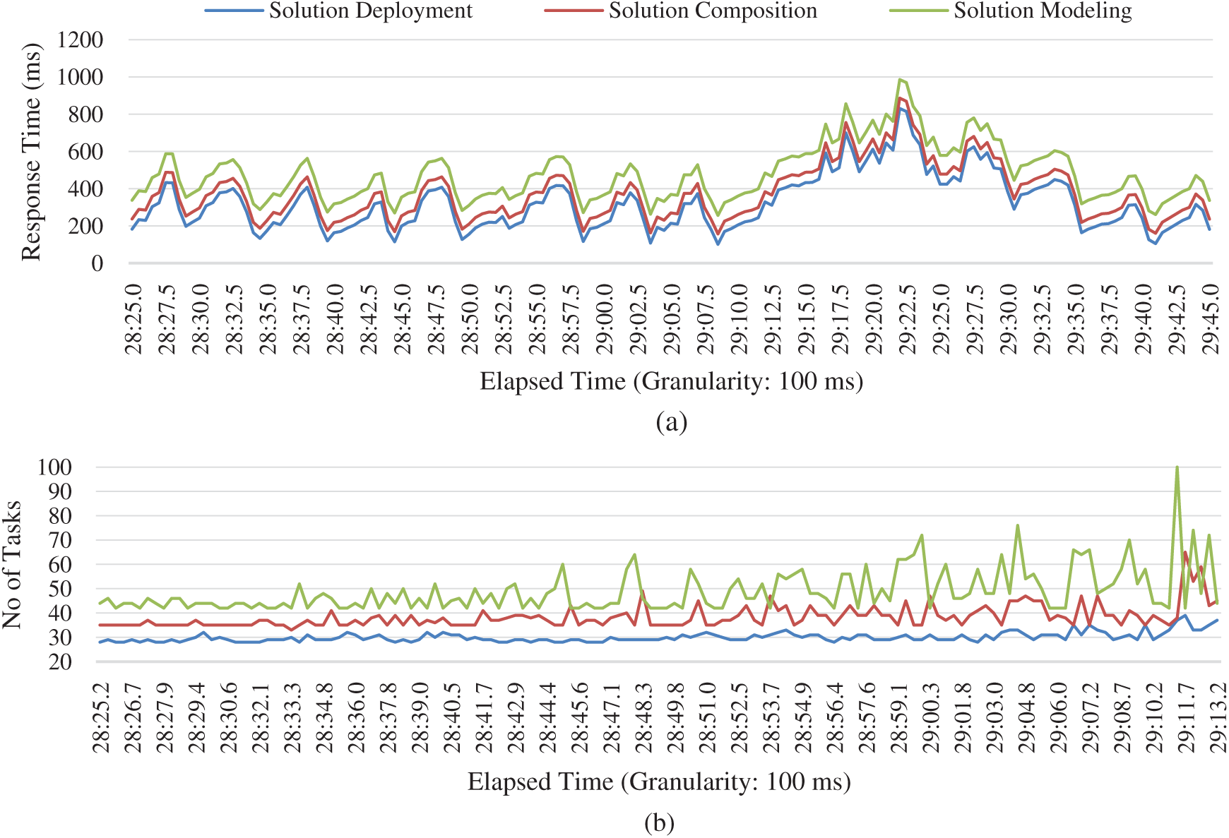
Figure 9: Scalability evaluation based on throughput and response over time (a) Page response over time (b) Throughput
Complex problem solving is everyday human life problems that cannot be easily approached due to many contradicting goals and parameters. The approach towards solving complex real-world problems has been purely based on human cognition and manual process. The expert-based solution has more human cost and has more chance of errors. In this paper, a novel reference architecture has been proposed to employ artificial cognition to solve complex problems with modern task orchestration technologies. This paper serves a design pattern for complex problem solution which involve different parameters and different goals. The pattern on which the architecture is built is the optimization, prediction, scheduling, and control. As part of the paper's goal, we have designed the architecture by leveraging software best practices of modularity and coupling. We have employed DIY planes, which encourages the non-technical people also to compose their problems. This increases the contributing hands in the society and encourages people with less technical depth yet with creative skills to tinker with technologies and contribute their thinking without the need to code and dig deep in the technical aspect.
The proposed architecture makes use of task orchestration technologies to add flexibility and scalability to the approach. It provides users with interfaces to describe their problems, compose their solutions and deploy them. The proposed architecture is easy to use and robust from faults. It is scalable even in peak time and gives adequate processing time.
Funding Statement: This research was supported by Energy Cloud R&D Program through the National Research Foundation of Korea (NRF) funded by the Ministry of Science, ICT (2019M3F2A1073387), and this research was supported by Basic Science Research Program through the National Research Foundation of Korea (NRF) funded by the Ministry of Education (2018R1D1A1A09082919), and this research was supported by Institute for Information & communications Technology Planning & Evaluation (IITP) grant funded by the Korea government (MSIT) (No. 2018-0-01456, AutoMaTa: Autonomous Management framework based on artificial intelligent Technology for adaptive and disposable IoT). Any correspondence related to this paper should be addressed to Dohyeun Kim.
Conflicts of Interest: The authors declare that they have no conflicts of interest to report regarding the present study.
1. X. Feng, Y. Laurence, W. Lizhe and V. Alexey, “Internet of things,” International Journal of Communication Systems, vol. 25, no. 9, pp. 1101–1104, 2012. [Google Scholar]
2. A. F. Shams, H. Kashfi and B. Farahani, “The evolving enterprise architecture: A digital transformation perspective,” in Proc. of the Int. Conf. on Omni-Layer Intelligent Systems, Crete, Greece, pp. 179–183, 2019. [Google Scholar]
3. O. Vermesan, P. Friess, P. Guillemin, S. Gusmeroli, H. Sundmaeker et al., “Internet of things strategic research roadmap,” Internet of Things-Global Technological and Societal Trends, vol. 1, no. 2011, pp. 9–22, 2011. [Google Scholar]
4. F. Xia, L. T. Yang, L. Wang and A. Vinel, “Internet of things,” International Journal of Communication. Systems, vol. 25, no. 1, pp. 1101–1102, 2012. [Google Scholar]
5. S. Ahmad, L. Hang and D. Kim, “Design and implementation of cloud-centric configuration repository for DIY IoT applications,” Sensors, vol. 18, no. 2, pp. 474–494, 2018. [Google Scholar]
6. S. Ahmad, I. Hussain, M. Fayaz and D. Kim, “A distributed approach towards improved dissemination protocol for smooth handover in mediaSense IoT platform,” Processes, vol. 6, no. 5, pp. 46–61, 2018. [Google Scholar]
7. S. Ahmad, S. Malik, I. Ullah, M. Fayaz, D. H. Park et al., “An adaptive approach based on resource-awareness towards power-efficient real-time periodic task modeling on embedded IoT devices,” Processes, vol. 6, no. 7, pp. 90–116, 2018. [Google Scholar]
8. S. Ahmad, S. Malik, I. Ullah, D. H. Park, K. Kim et al., “Towards the design of a formal verification and evaluation tool of real-time tasks scheduling of IoT applications,” Sustainability, vol. 11, no. 1, pp. 204–226, 2019. [Google Scholar]
9. D. Dietrich and J. Funke, “Complex problem solving: What it is and what it is not,” Frontiers in Psychology, vol. 8, no. 1, pp. 1153–1166, 2017. [Google Scholar]
10. G. Samuel, F. Andreas, S. Matthias and W. Sascha, “Assessing complex problem-solving skills with multiple complex systems,” Thinking and Reasoning, vol. 21, no. 3, pp. 356–382, 2015. [Google Scholar]
11. E. Beate, G. Frank, G. Samuel, P. Liene and N. Johannes, “The role of planning in complex problem solving,” Computers and Education, vol. 128, no. 1, pp. 1–12, 2019. [Google Scholar]
12. C. Yunxiao, L. Xiaoou, L. Jingchen and Y. Zhiliang, “Statistical analysis of complex problem-solving process data: An event history analysis approach,” Frontiers in Psychology, vol. 10, no. 1, pp. 486–509, 2019. [Google Scholar]
13. S. Gupta, “Complex problem solving and internet of things,” Thingsmatrix, 2015. [Online]. Available: https://thingsmatrix.com/2015/09/12/leveraging-internet-of-things-iot-in-solving-complex-business-prob- lems/. (Accessed 05-28-2020). [Google Scholar]
14. S. Ahmad, A. Khudoyberdiev and D. Kim, “Towards the task-level optimal orchestration mechanism in multi-device multi-task architecture for mission-critical IoT applications,” IEEE Access, vol. 7, no. 1, pp. 140922–140935, 2019. [Google Scholar]
15. S. Ahmad and D. Kim, “A multi-device multi-tasks management and orchestration architecture for the design of enterprise IoT applications,” Future Generation Computer Systems, vol. 106, pp. 482–500, 2020. [Google Scholar]
16. C. Federico, C. Ivica, D. R. Davide, M. Ivano, P. Patrizio et al., “Model-driven engineering for mission-critical iot systems,” IEEE Software, vol. 34, no. 1, pp. 46–53, 2017. [Google Scholar]
17. R. Casadei, G. Fortino, D. Pianini, W. Russo, C. Savaglio et al., “A development approach for collective opportunistic edge-of-things services,” Information Sciences, vol. 498, no. 1, pp. 154–169, 2019. [Google Scholar]
18. V. Karima, A. D. Perez, G. Diogo, B. Luiz, C. Marilia et al., “Service orchestration in fog environments,” in IEEE 5th Int. Conf. on Future Internet of Things and Cloud, Prague, Czech Republic, pp. 329–336, 2017. [Google Scholar]
19. V. Karima, A. D. Perez, R. M. Marcio, S. Carlos, G. Diogo et al., “Fog orchestration for the internet of everything: State-of-the-art and research challenges,” Journal of Internet Services and Applications, vol. 9, no. 1, pp. 1–23, 2018. [Google Scholar]
 | This work is licensed under a Creative Commons Attribution 4.0 International License, which permits unrestricted use, distribution, and reproduction in any medium, provided the original work is properly cited. |