DOI:10.32604/cmc.2021.017394
| Computers, Materials & Continua DOI:10.32604/cmc.2021.017394 | |
| Article |
Enabling Reachability Across Multiple Domains Without Controller Synchronization in SDN
1Department of Computer System and Technology, Faculty of Computer Science and Information Technology, University of Malaya, Malaysia
2Department of Computer Science and IT, University of Malakand, Pakistan
3Robotics and Internet-of-Things Lab, Prince Sultan University, Riyadh, Saudi Arabia
4Department of Computer Science, College of Computers and Information Technology, Taif University, Taif, 21944, Saudi Arabia
5Department of Computer Science, College of Sciences and Arts Rass, Qassim University, Buraydah, 51452, Saudi Arabia
*Corresponding Author: Rosli Bin Salleh. Email: rosli_salleh@um.edu.my
Received: 29 January 2021; Accepted: 11 April 2021
Abstract: Software-defined networking (SDN) makes network agile and flexible due to its programmable approach. An extensive network has multiple domains in SDN for the scalability and performance of the network. However, the inter-domain link is also crucial for the stability of the entire network on the data plane layer. More than one inter-domain connection enhances the scalability of the data plane layer. However, it faces a reachability problem with the principal root, which causes forwarding loops and packet drops in the network, thereby degrading network performance. The proposed solution is a multiple controller architecture; however, this approach increases the complexity and affects network performance. Thus, in this study, we propose a framework that avoids forwarding loops and packet drops without the synchronization of multiple-domain controllers in the network using an avoid loop with test packet scheme. Moreover, we collect the link status for improved routing and load balancing for the upcoming flow across inter-domain links to prevent congestion and increase throughput in real time. Our proposed methodology can significantly reduce the controller workload against multiple controller architecture, minimize flow setup latency, and improve throughput.
Keywords: Multiple domain; packet drop; forwarding loop; load balancing; SDN; multiple controller
In the last decade, software-defined networking (SDN) technology has attracted considerably increasing attention in industries and the academia. It is a nascent technology that has been adopted in data center networks and wide-area networks (WAN), such as Internet2 and Google B4 [1,2]. SDN depends on a central controller to hold a global view of the entire network and perform fine-grained traffic engineering in a centralized manner. It has proven superior performance in load balancing, maximizing system throughput, and dynamic adaptability of traffic changes [3]. It also enhances the simplicity in network configuration and management due to its centralized architecture. Moreover, SDN enhances innovation and flexibility with programmable networks by decoupling the control plane from the data plane [4]. The traditional distributed computer network has many problems than can be overcome by SDN. However, innovation in the conventional network is a challenge due to its nonprogrammable approach [5].
The controller contains the authority of high-level policy decisions to construct the high-speed data plane of network devices [2]. The OpenFlow protocol is used to communicate with the controller and the data plane through the southbound application programming interface (API) [6]. The controller uses OpenFlow to install the forwarding rules in network devices (i.e., switches and routers). OpenFlow has several versions that have been released, from its first version (1.1) in 2011 to the latest one (1.6). Every new version of the OpenFlow protocol adds new functions [7]. In addition to the control and data planes, SDN has a third plane called management or application plane. This plane interacts with the controller through the northbound API. With this plane, the administrator and network engineer can deploy their network applications, such as load balancers and routing protocols, which allow them to control the data plane according to their requirements. The SDN is not only limited to the enterprise or the data center network but it also has a beneficial effect on the improvement of the performance of wireless technologies, such as 5G. Previous research has shown its footprint in the upcoming 6G technology [8].
In SDN, multiple-domain concepts make large-scale networks, such as carrier-grade networks, stable and efficient. In a conventional network, the carrier-grade network is divided into multiple autonomous systems to monitor and efficiently route and reduce each router processor overhead [9]. The same concept of multiple domains is applied in SDN to make the network stable and offload the network controller with multiple physical controllers’ deployment. The single-controller SDN is inappropriate for the whole network due to the degradation of controller computational performance, which affects the network performance [10]. The distributed physical control plane in the control layer reduces the events of the data plane. Chunks of the network should be created into multiple domains to make the network scalable. In this manner, the small portion of the network will be managed excellently to improve the performance of the data traffic throughput, minimize the computational overhead, and reduce the flow insertion latency delay [11].
The problem in multiple domains without controller synchronization creates forwarding loops and packet drops in the network, which lead to reachability problems across multiple domains in end-to-end services [12]. Given a flow, its forwarding path forms a loop, such that the packets of the flow will ultimately be forwarded to their originating domain due to the non-update of the control plane. If a loop exists, then a single looped frame can sufficiently decrease the performance of the entire network by consuming the bandwidth and CPU power of the affected devices [13,14]. To overcome such problems, distributed hierarchical and flat-controller architectures have been proposed; however, some limitations exist in the distributed architecture of controllers, such as flow setup latency in the hierarchical architecture and controller CPU computational overhead in the flat architecture of SDN [11]. In the present study, we primarily focus on the reachability problem without loop intervention and packet drops in the inter-domain communication during the absence of inter-controller communication in SDN. We propose the avoid loop with test packet (ALTP) mechanism to prevent loop intervention and measure the end-to-end latency in the network from the source to the destination in the absence of multi-domain controller synchronization.
The other problem in SDN controller is its routing. SDN can use a single-path shortest-path first (SPF) algorithm, which creates congestion on inter-domain links because the controller instructs the switches to forward all flows from the source to the destination on the same path [15]. If redundant inter-domain links exists, then the controller uses the single link, and the other link remains unoccupied. In the SPF algorithm, packets may be dropped if the inter-domain link is congested. All flows belong to one link during the inter-domain data traffic. In this study, splitting the flow from the source to the destination is made possible. In the inter-domain flow, the controller accommodates multiple flows across multiple paths from the source to the destination, and the throughput is increased.
This study also investigates the concerns mentioned above. It assesses how packet drops/loops occur if the source and destination belong to different domains. Moreover, this study enhances our previous work [16] with the main contributions as follows:
• Detailed description of the proposed methodology;
• Updated topology module to handle the real-time link bandwidth availability;
• Load balancing among inter domains to improve the overall throughput of the entire network;
• Flow installation on switches according to flow demand;
• Analysis of multiple controller architecture and default inter-domain routing performance using the proposed framework.
In the production network, the network designing team suggests redundant links in the core layer, and the important egress node makes the network scalable and reliable in case of link failure. On the basis of this principle, a single inter-domain link is not appropriate for the scalability of the entire network, which contains multiple domains. If one link in the inter-domain connection fails, then it will create the end-to-end reachability problem across all the domains of the network. We analyze that one inter-domain link does not create a loop. We install two links among the domains for reliability purposes, and we analyze whether a reachability problem in the multi-domain system occurs. After the excavation of the problem, we obtain two root causes of the forwarding loops and black hole problems in the network.
In Fig. 1, the controller has its own entire domain information. Thus, the entire domain topology tree can be constructed quickly [5]. Packet drop may occur due to the inter-domain communication without controller synchronization because the controller has broadcasted ARP packets inside and outside the topology, which mislead the controller about the host location. Thus, in this manner, wrong flow entries will be incorporated due to the NIB table of controllers not being updated. The redundant link has the same properties as Link 1 in Fig. 1. In this step, the controller misleads and constructs a wrong topology. That is, it installs the outflow forwarding rules on Switch H instead of Switch E.
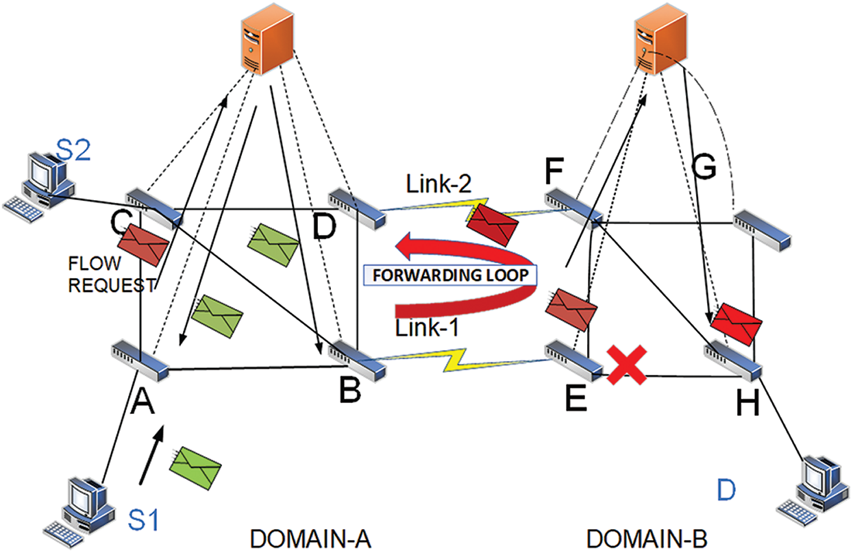
Figure 1: Forwarding loops and packet drops among the inter domain with dual link
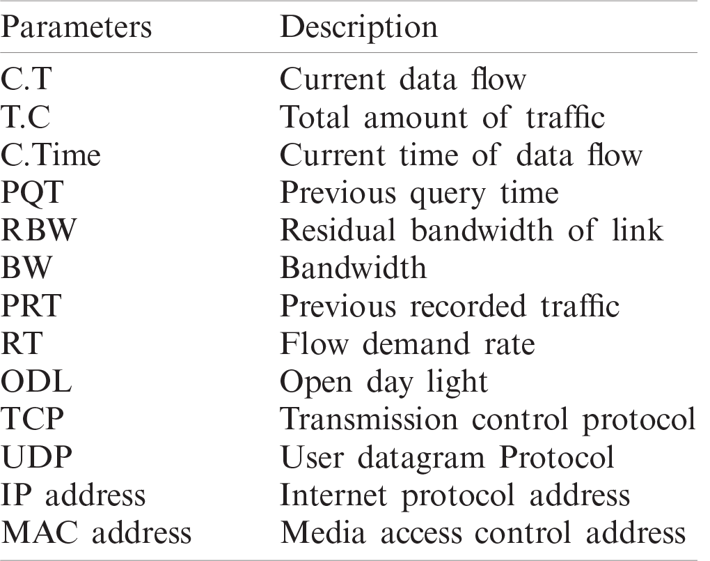
The packet drops on Switch E, and Host B cannot receive the packets; or if the host is not present in the network, then it will create a forwarding loop. The cases mentioned above indicate that if the controller does not know the complete network view, then avoiding the loops/packet drops between domains will be difficult, as well as drawing the right tree topology for the data traffic in their domain. Loop also occurs in the three domains due to the NIB table of controllers being not updated [12,17]. Acronyms used in this paper are presented in Tab. 1.
The remainder of this paper is structured as follows. Section 2 describes the related works. Section 3 briefly explains the proposed methodology. Section 4 presents the results and discussions. Finally, Section 5 concludes the paper.
Several works have been conducted to make the reachability of one host in one domain to another domain with multiple controller architecture possible. HyperFlow [18] and ASIC [10] were proposed, in which several distributed controllers work together in the flat topology of controllers. This approach enables end-to-end services, provides control layer scalability, and sustains the flexibility of the centralized system. However, flat architecture controllers need supplementary protocols, such as the Border Gateway Protocol (BGP). The detail of other domain information acquired by every controller in the network brings the computational overhead with additional resource utilization. Its computational overhead is linear to the topology size [19]. HyperFlow [15] uses a distributed file system and hash table for spreading the information across the various controllers to sustain logical centralization. The other distributed controller approach, DISCO, is a multi-domain, distributed SDN controller with intra-and inter-domain functions [20]. The intra domain manages network control and flow prioritization. With the module package, the intra domain addresses several network problems. The inter domain provides connectivity and has two modules among different controllers. First is the messenger module for building channels between the controllers to exchange data with each other. The AMPQ protocol, which provides routing, prioritized querying, and orientation messaging, is used in this approach. The controller has high workload and CPU overhead in this strategy because each controller carries the entire network information and performs routing for inter and intra domains [11].
Google also has inter-domain experience with B4 [1,2], a global SDN deployment that connects its data centers to each data center with unified traffic engineering services and controller clusters. Contact between controllers allows the exchange of information between the various controllers of SDN. Inter-controller communication can be implemented in various ways. One is the SDN east–west interface approach. The SDN east–west interface is used under the jurisdiction of single- or multiple-network operators to share information between SDN domains. In between two controllers, a session needs to be formed by adopting either the BGP or the Session Initiation Protocol (SIP) over the Transmission Control Protocol (TCP) to transfer information. If it needs to handle more than the adjacent controllers, then it cannot be used. The SIP can be used to set up an SIP; that is, for initiating and controlling communication, SIP is a request–response protocol [10].
Conversely, in Kandoo [21], the hierarchical distribution of controllers is defined based on two layers of controllers. First is the lower layer, which is a group of controllers without interdependence and network-wide state information. Second is the upper layers, which are a central management controller that maintains the network-wide state and inter-domain flows through the root controller for inter-domain traffic. These layers have high flow setup latency for inter-domain routing because the local controller consults with the controller at each new inter-domain flow setup, thereby affecting network performance [11].
Existing studies [22–24] have proposed solutions to distribute the load on the control plane through load balancing and QOS approaches across multiple controllers. These techniques aim to alleviate the load on the controller in flat and hierarchal controller architectures. Previous studies have focused on the load but have not extended their research to different domains and geographical locations where the controller maximizes the flow setup latency due to long distance. However, our work is different from these studies, as we offload the controller and avoid the complexity of multiple controller interactions. Our proposed work is also feasible to the controller for different geographical locations because every controller is free from other domain workloads.
In SDN-based networks, load balancing in data planes can be classified into two parts: servers and links. In server-based load balancing, traffic is allocated to different servers to avoid network congestion. Conversely, link load balancing intends to distribute the flows to different paths to adjust link utilization [25].
The equal-cost multi-path (ECMP) algorithm has also been proposed in SDN, as well as other well-known techniques in the traditional network for load balancing [26]. However, this algorithm works on the static link cost, which is proportional to the link bandwidth and is preferable for data centers. Another study formulated a dynamic flow scheduling algorithm based on elephant and mice flow in data centers [15]. In [27], the authors proposed an architecture that uses the distribution of the network link utilization and periodic probe packet in the data center network. In [28], difflow design was proposed to use the ECMP strategy for short-term flows and random packet spraying; the design is based on the distribution of the long- and short-term flows in the data center. The above data plane load balancing strategy has been suggested for splittable flows in the enterprise or in the data center network.
In this study, we address the inter-domain link load balancing strategy, which focuses on the real-time availability of the link cost and the unsplittable flow problem in a WAN under multiple domains. However, the above proposed algorithms are not tested in this study experimentation.
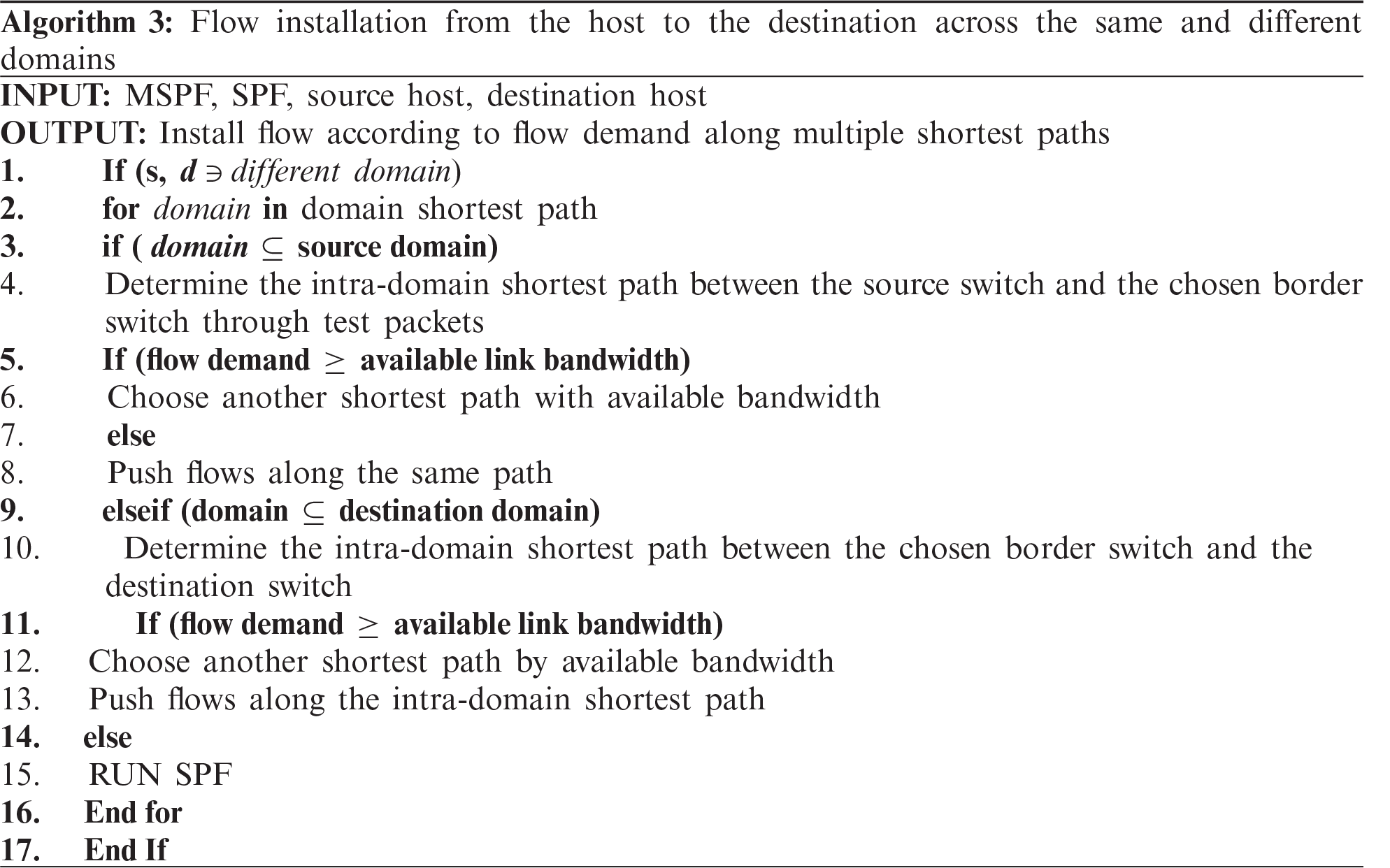
The objective of our proposed methodology is to solve the reachability problem and enable end-to-end services in the whole network without the synchronization of control planes. The proposed method can offload the controller from other domain information and improve network performance. To the best of our knowledge, this study is the first to enable reachability without controller synchronization
The overview workflow of our proposed approach is shown in Fig. 4. The proposed approach includes four modules, namely, topology discovery and update module, ALTP scheme (test packet and delay module), flow installation module, and load balance module. These modules are briefly described as follows.
• Topology Discovery and Update: The approach proposes a two-level topology discovery. The first level is the intra-domain level that discovers the internal topology of a domain and identifies the border switches and links. The controller obtains the information from switches among the link bandwidth utilization and updates the topology. This result is also used as the input in the load balancing module.
• Flow Classifier: This submodule classifies the flow into inter and intra domains.
• ALTP Scheme: The module calculates the shortest delay path(s) between the source and border nodes for inter-domain flow by using test packets. The result is used in the flow installation and load balance modules.
• Load Balance: If several shortest paths with a dynamic cost exist between the source–destination host pair from the path computation, then this module will balance the flow according to its demand among the shortest paths’ status from one domain source to other domain destination.
• Flow Installation: The module pushes flows in the related border switches along the domain-level shortest path between source–destination host pairs, and it pushes inter-domain flows in the relevant border switches along the shortest path within a domain.
3.1 Topology Discovery and Update
This module obtains information about the switches, such as attached host ID, MAC addresses, and IP addresses, from an underlined infrastructure layer through a controller. The controller obtains this information through Link Layer Discovery Protocol (LLDP) to identify the topology [5]. The LLDP packets are sent by switches through the controller instructions. The importance of LLDP packets is the same as in a conventional network because it propagates the source switch outport, identities, and other capabilities. In SDN, when the controller receives LLDP from the switches, the controller analyzes the packets, identifies how many switches and hosts are connected in the domain, and builds the topology graph according to the information it obtained.
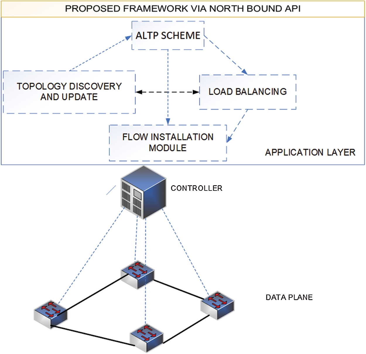
Figure 2: Proposed framework for end-to-end services across multiple domains without controller synchronization
The precise network states information availability. The controller manages the topology by updating the residual connection capabilities in this module after installing a flow. For a given flow demand, the controller computes a route for flow demand. It then subtracts the requested demand from each link’s residual capacity on the computed route. Therefore, the controller will always have the current residual graph to compute a path for a new request. Clearly, if only one physical controller exists and no background traffic is present when we execute our simulation, then we can use this idealistic approach.
In our work, the controller sends the port statistics requests to all OpenFlow switches every 2 s. Upon receiving this request from the controller, each switch sends the total amount of traffic sent on its ports until the request comes. The controller keeps following the quantities [29].
where T.C (u, v) is the total amount of traffic sent through link (u, v) until the current time tc, and PRT (u, v)is the previously recorded total amount of traffic sent through link (u, v) until the previous query time PQT. By using these quantities, the controller can update the residual bandwidth of link (u, v) as follows. In Eq. (1), C.T (u, v) is the average current traffic rate. Then, in Eq. (2), RBW (u, v) denotes the residual bandwidth and is calculated by subtracting C.T (u, v) from BW (u, v), which is the initial capacity of the link. Finally, the controller uses the following equations to save the current quantities as previous quantities for the calculations in the next period. In Eq. (3),
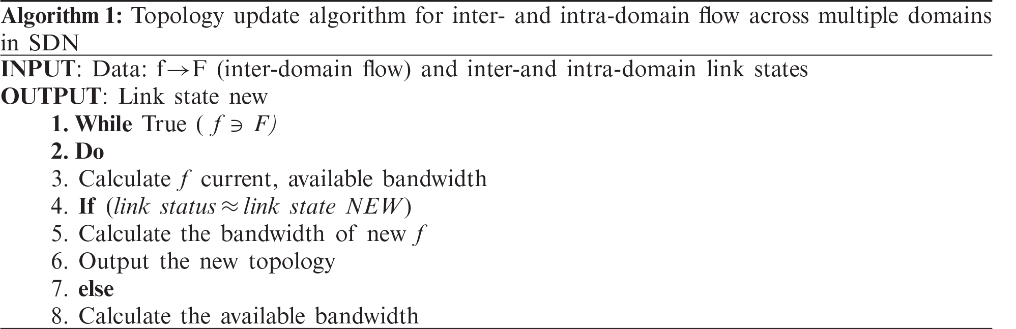
This algorithm achieves the most recent link state information from the underlying network and updates the link information in real time.
a. Flow Classifier
In the implementation, one job is to identify the application data for inter-domain flow level services. Generally, methods that are commonly used to distinguish flows are based on source IP address, source port, MAC address, service type (ToS) bits, and traffic class header field in the MPLS [31]. We classify user data flow in our inter-domain routing strategy into inter and intra domains. The variable may differentiate data flow by setting the match fields (i.e., source IP and MAC addresses and destination IP and MAC addresses) of the flow entries in OpenFlow switches.
Controllers know their inter-domain switches and status connections based on the analysis of the problem. In their domain, they prevent loops and assess an optimal path within the domain. However, controllers cannot compute the path outside their domain. We use test packets to prevent loops and packet drops among multiple SDN domains and obtain delay routes. While transmitting the data from the source to the destination, it chooses an optimal connection from the inter-domain links. The new data plane and the split definition of SDN are not introduced in this study. The ALTP is added to the switches without any modifications. Echo and response packets are the test packets in our scheme. The proposed scheme is presented in Fig. 4. The ALTP’s characteristics are as follows. First, the source sends packets to the destination. If the destination belongs to another domain, then the controller sends a test packet to another domain in the network using inter-domain links. The source domain controller will be responsible for the source domain and test packet transmission. The controller holds one inter-domain connection and will block the rest of the inter-domain links. If no other domain exists, then the packets are dropped by the controller. The inter-domain links follow the same procedure on the second link to N, and the controller keeps the response time value of the test packets. The controller determines and matches up the test packets’ delay rate, and it selects that link for data traffic based on the rapid response and lower delay rate of the test packet. The controller randomly selects any link in the event of an equal response time. It injects a test packet to Switch A in Fig. 3, where the request initially comes to the controller of Domain A to select an optimized path to the destination. At that point, the controller checks its RIB. Suppose that the IP and MAC addresses do not match. The controller will find the MAC address by using ARP broadcast and will forward outside Domain B. When the domain controller obtains the MAC address of the following destination, it will set forwarding rules from source Switch A to egress Switch B for Test Packet 1. Thus, the test packet will send through Link 1. The path of the metric for Test Packet 1 is A–B–D–F (echo packet path). The reply path for the test packet path is recursive of the echo path F–D–B–A.
All the steps for Test Packet 2 are similar to those of Test Packet 1. The metric for the echo path of Test Packet 2 is A–B–E–H, and the reply packet path is H–E–B–A. Consider the test packet path latency by the propagation delay (
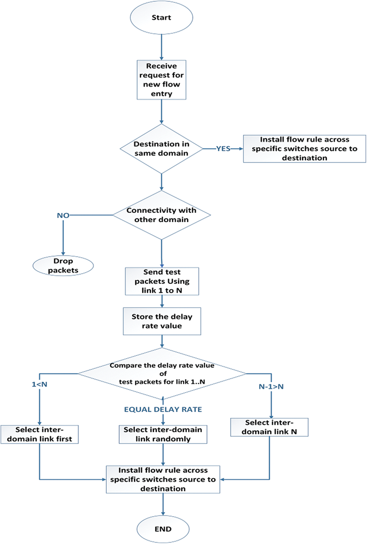
Figure 3: ALTP scheme flowchart
3.3 Inter-Domain Load Balancing Module
In our proposed framework, the controller categorizes the flow into inter- and intra-domain flows, as shown in Fig. 2. In this case, we are interested the inter-domain flow. The test packet obtains the end-to-end delay path from the source node to the destination node and selects the least delay path, which includes the inter-domain link. This approach results in the flow installation module and installs the source node’s flow to select the border switch. The inter-domain link is selected among the inter domains, as shown in Fig. 5. Thus, all flows from Sources 1 and 2 forward the flow on this link. However, we assume the load balancing problem and maximize the path for inter-domain flow. In this case, we assume the inter-domain flow in the network with the absence of intra-domain flow. We also assume here in the network that the test packet selects the least inter-domain link for inter-domain flows, where it selects one of the border switches as the gateway. We consider multiple flows simultaneously. The problem becomes related to the integer multi-service flow problem, which is known to be NP-hard. Moreover, in many applications, each flow must be transferred through a single path. Suppose Flows 1 and 2 have the same demand cost likewise, Flow 3 has 10, and Flow 4 has 5 cost demand bandwidths. Thus, f1–f3 have their demands fulfilled, whereas the other flows have demanded more and will be rejected. We sort out such problem through a multi-flow path heuristic routing algorithm called rate-based dynamic shortest path [32], which is also known as multiple shortest paths first (MSPF) [29]. This algorithm works on the dynamic cost of the link. The proposed algorithm for a single domain with a dynamic cost is used for the multiple-domain problem in this study.
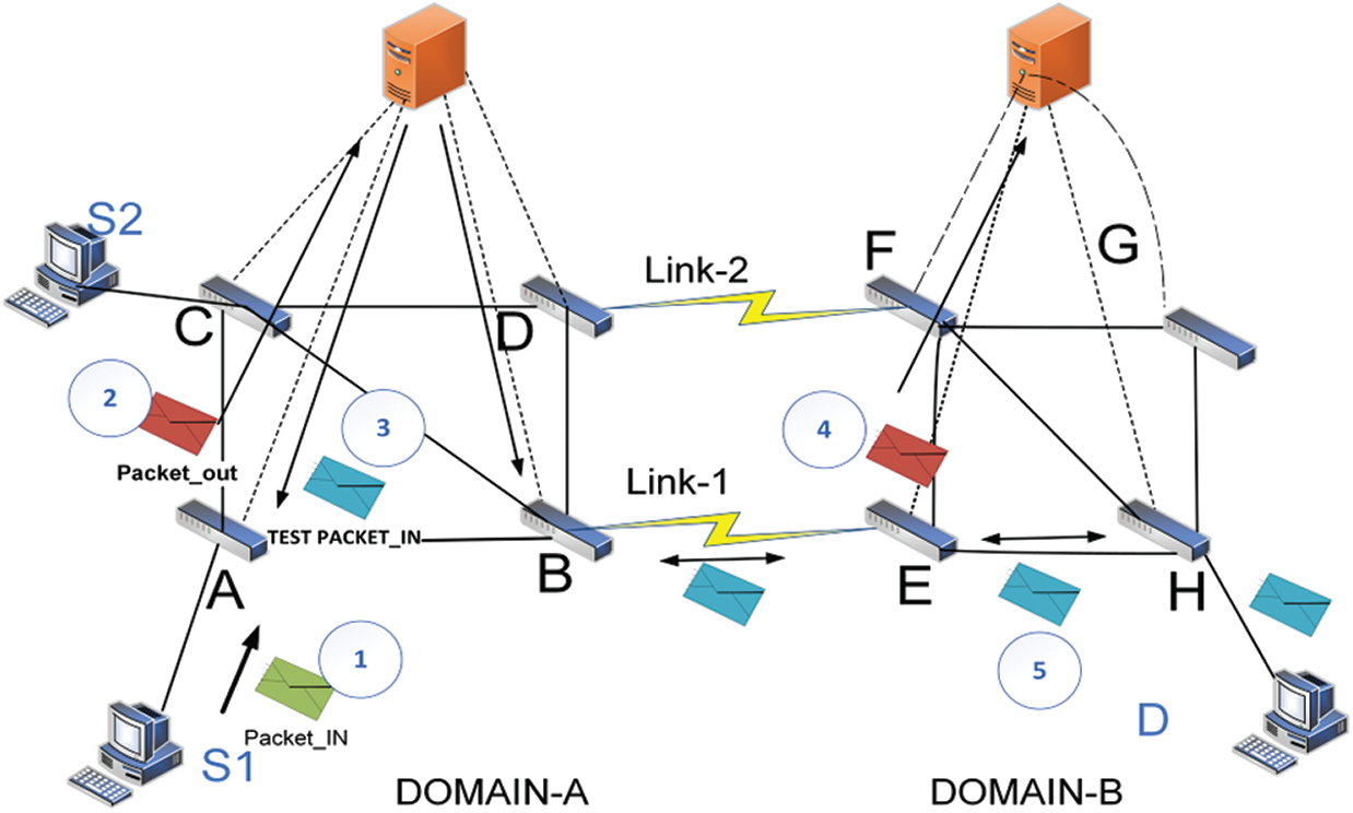
Figure 4: Installation of test packets across inter-domains using links 1 and 2
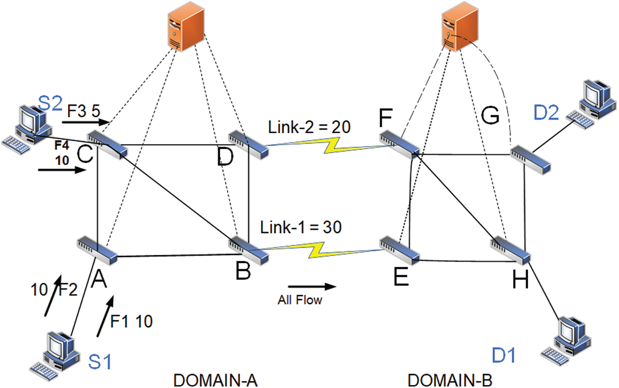
Figure 5: Inter-domain flow installation from S1 and S2 across inter-domain Link 1 through SPF
Consider a network represented by a directed sample graph
Each link
The MSPF works on a dynamic link cost metric as follows:
To compute for
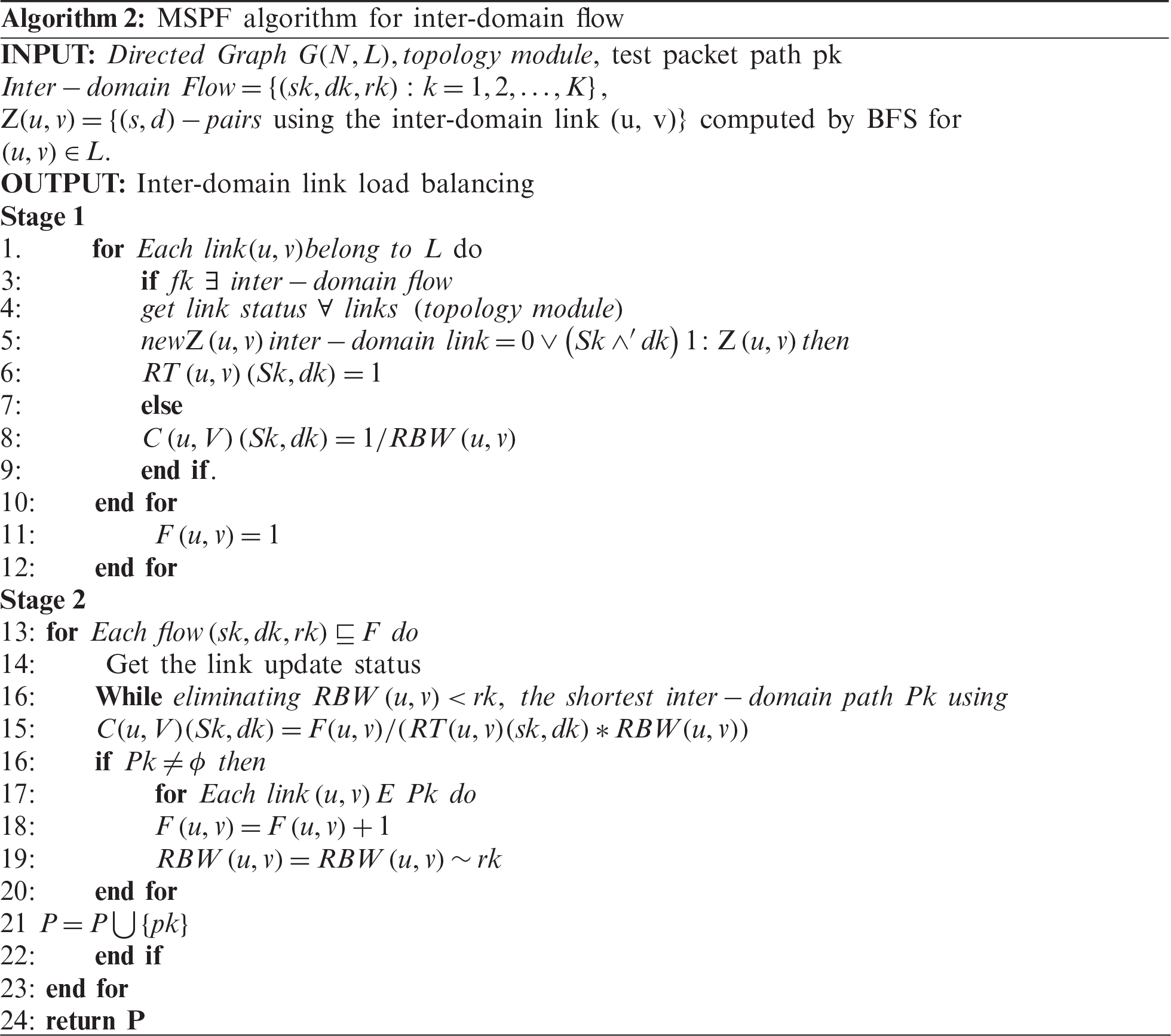
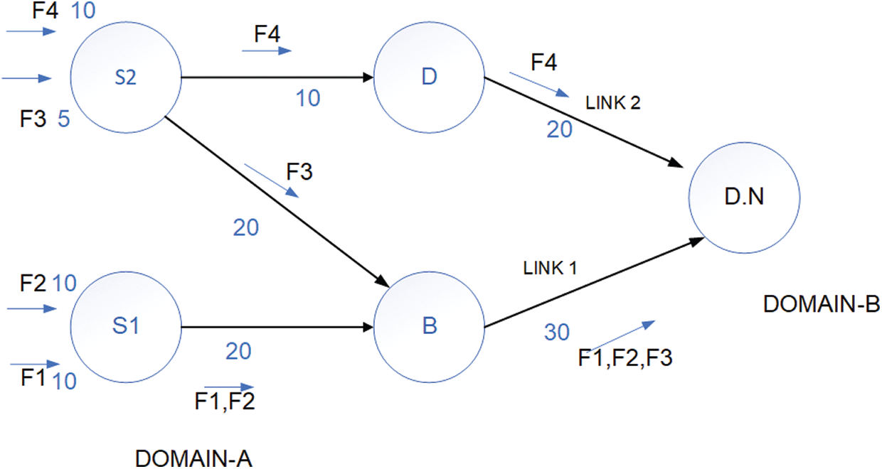
Figure 6: Distribution of multiple flow across multiple shortest paths
We obtain the domain topology and then compute the shortest path on the domain level. When the controller of the source domain receives the first packet sent by a source host to a destination host in the other domain (packet in the event), it needs to install inter-domain flows in the border switches according to the shortest path [33]. Normally, the controller will make a forwarding decision based on the destination MAC address. However, for the inter-domain traffic, the forwarding decision is also based on the destination IP address. Thus, the controller needs to distinguish the intra-domain traffic from the inter-domain traffic to process these types of flow properly. According to the installation module, the MSPF uses the dynamically shortest path according to the link status and balances the flow load across the domains. The test packets obtain the best-optimized path end-to-end.
4.1 Parameters for Experimentation
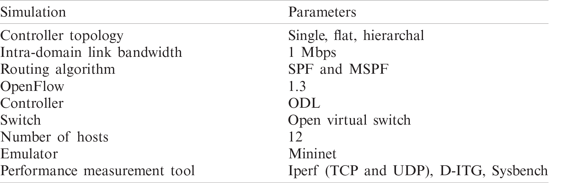
This section evaluates the proposed methodology for dual domains in SDN. The simulation contains one PC system with 2.1 GHZ Core i7 process and 32 GB main memory. The experiment is performed in the Mininet emulator with the ODL controller [34]. We use a random number of switches and a maximum of three controllers in the hierarchy architecture and two in flat-controller architectures. In the data plane, domains are connected to the border switches. A half-mesh ring topology is selected for the experiments. The two domains are connected by two links (i.e., Links 1 and 2). Every link inside the domain is 1 Mbps, whereas the delay time of every link in both domains is 10 ms. The experiment is performed a minimum of 10 times to check the reliability of the proposed study and verify the performance. The proposed framework minimizes the control plane workload, which also improves the end-to-end delay and increase the throughput. The simulation paraments used in this experiment are listed in Tab. 2.
Table 2: Parameters for experimentation
4.2 TCP and UDP Throughput Assessment
We set up 12 hosts for the TCP and UDP throughput assessment. Six hosts (h1–h6) are in the source domain, whereas the other six hosts (h7–h12) are in the destination domain. Moreover, we map a one-to-one relationship between the client and the server. The entity from h1 to h6 is the client in the source domain, whereas that from h7 to h12 is the server in the destination domain. The first three hosts (h1–h3) include the UDP traffic generator client, whereas h4–h6 are considered for a TCP client in the source domain. We use the Iperf tool to evaluate the TCP and UDP traffic. After the evaluation for UDP and TCP traffic throughput, we take the average after every 50 s. In Eq. (7), TT is the traffic throughput, and Tn is the last host traffic throughput, which may be UDP or TCP.
The average path throughput from the UDP source to its UDP destination is shown in Fig. 7. Inter-domain links along the path are evaluated by using the data traffic UDP throughput. The results indicate the difference among single-path SPF and MSPF throughput for UDP traffic. Moreover, the MSPF improves the throughput due to the adoption of MSPF and load balance among inter-domain links. We use the 50 s interval for datapoint. The simulation is run for 300 s to gain measurement of the actual improvement of the throughput. Moreover, the traffic to the controller from the TCP source uses the TCP traffic to a different destination, as shown in Fig. 8. Thus, it will allocate the same inter-domain link to their destination, which is selected through test packets for the UDP source data traffic. The controller keeps the delay of the test packets and selects an inter-domain link with the lowest delay. The evaluation of both routing algorithm throughputs for the TCP traffic is shown in Fig. 8. The MSPF shows improvement in throughput due to its load balancing feature.
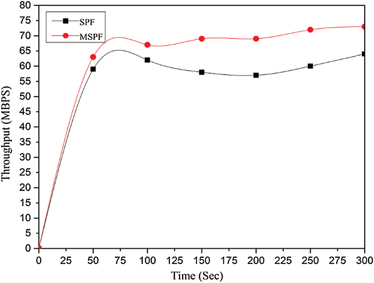
Figure 7: Inter-domain UDP flow average throughput
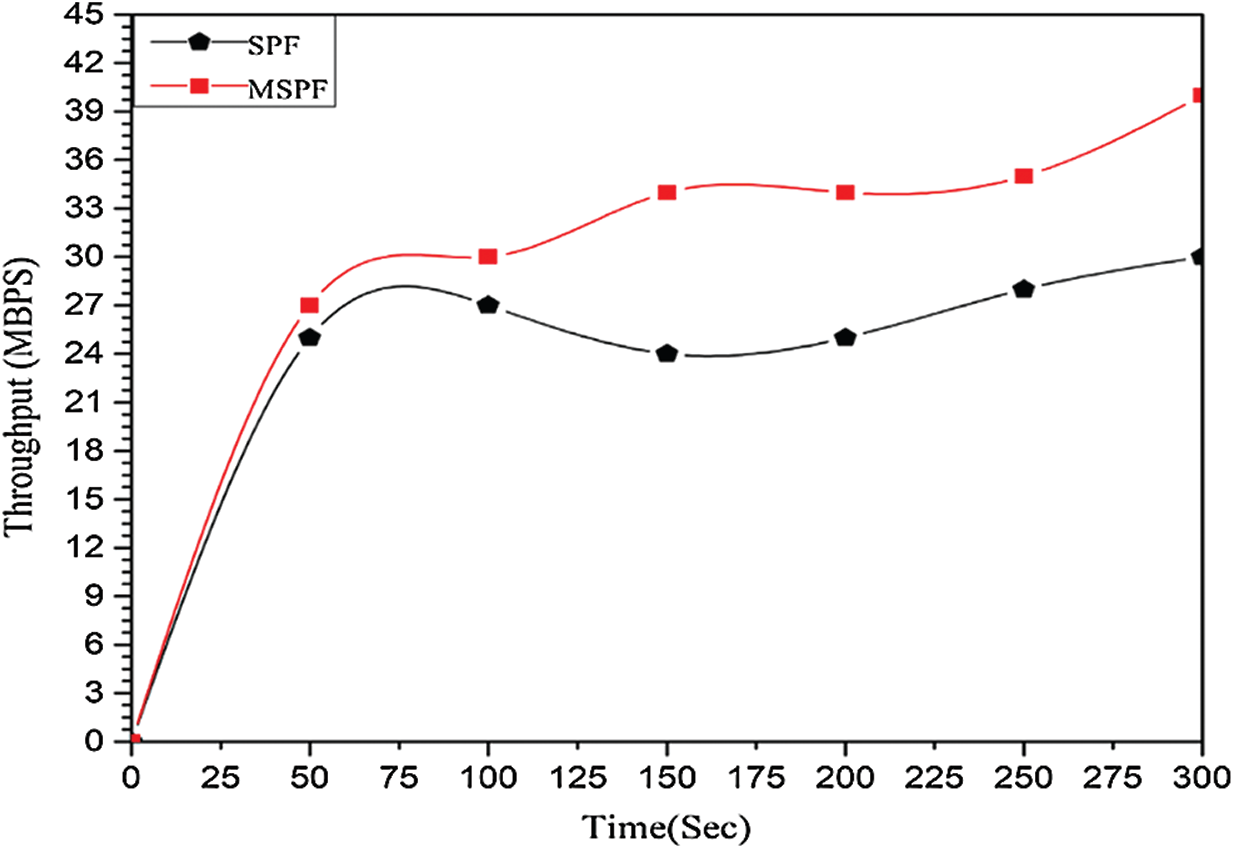
Figure 8: Inter-domain TCP flow average throughput
4.3 Evaluation of the Proposed Single-Controller Approach with Multiple Controller Architectures
We use the D-itg tool to run dynamic traffic for random packet generation from the source in one domain and the destination in another domain by using a random number of switches in the whole network (S1–S20). We use a maximum of 20 switches in both domains. Moreover, we increase the switches for the experiment in ascending order. Then, at every stage, we generate the inter-domain traffic and record the end-to-end delay. As shown in Fig. 9, we perform an end-to-end delay measurement, where end-to-end flow delay is also correlated with the flow setup latency. The single-controller architecture has an end-to-end delay that is relatively low compared with the remaining two architectures because of the less flow setup latency. Moreover, according to the five-switch topology, our proposed work’s end-to-end delay is two times less than the hierarchal approach and one time less than the flat approach, as shown in Fig. 9. The same trend of minimizing the delay is observed from 10 to 20 switches. Thus, some researchers have concluded that the hierarchical controller architecture is suitable for inter-domain routing [21,35]. However, our proposed methodology with a single controller has not only avoided the forwarding loop across the multiple domains but also improved the network performance.
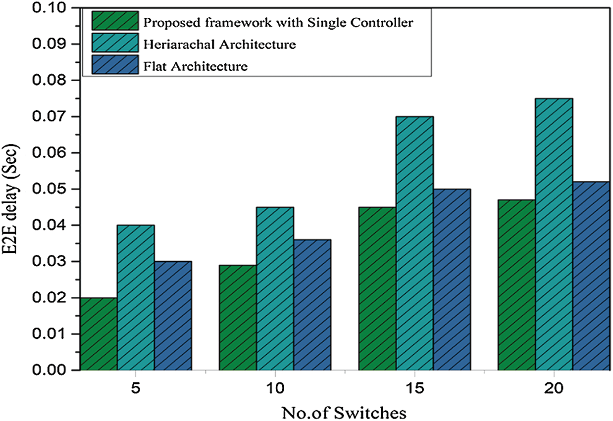
Figure 9: End-to-end delay under single- and multiple-controller architecture
In the hierarchical architecture, the controller has sufficient time to install flow for the inter-domain flow, which indicates that the interaction with the root controller will decrease the entire performance. As shown in Fig. 10, the difference between the existing architecture and our proposed approach with a single controller is that the former has relatively less flow setup latency in a maximum of 20 switches in the topology. Our proposed work has 35 ms flow setup latency for inter-domain flow, whereas the hierarchical architecture has quite a large flow setup latency at 70 ms, and the flat architecture has a latency of approximately 40 ms. Our proposed methodology and the flat approach have less flow setup latency due to the independence for inter-domain path calculation and flow installation along the path.
The Sysbench tool runs for 100 s for 5, 10, 15, and 20 switches individually. On every test, we take the peak value of CPU utilization for the proposed controller architecture and the rest of the architecture. The controller computational workload with our approach and the two other controller architectures is shown in Fig. 11. As shown by the difference of the load, our proposed approach also has less workload because it holds the information of its domain, and no other routing protocol and collaboration exist with the other domain controllers. In this experiment, the hierarchical controller has less workload because it is only used for inter and intra domains and flat architecture. The controllers constantly update each other in both domains for inter-domain flows via inter-domain routing [36,37]. If one controller has a specific capacity for the nodes in the network, then the hierarchical approach controller obtains half of that capacity.
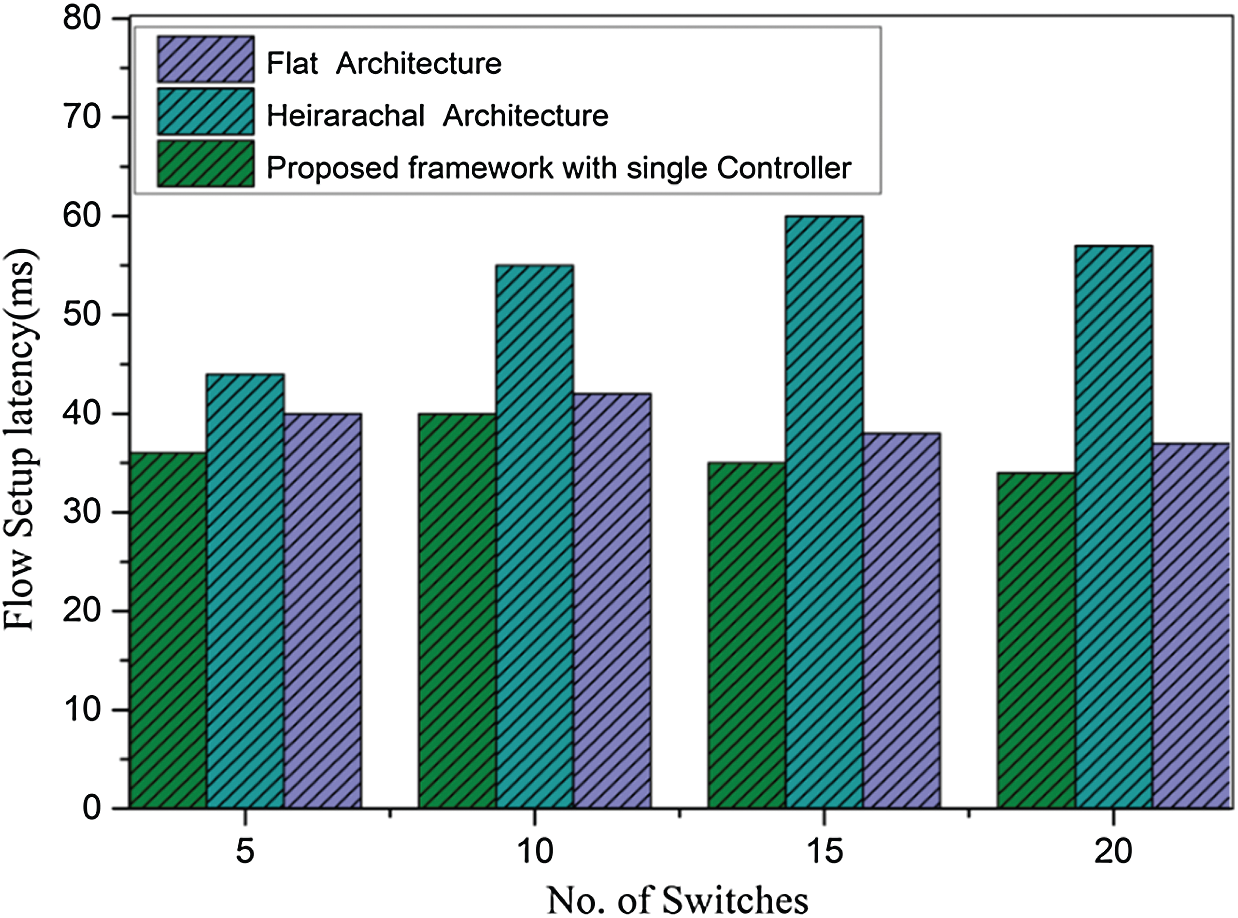
Figure 10: Flow setup latency measurement with single- and multiple-controller architecture
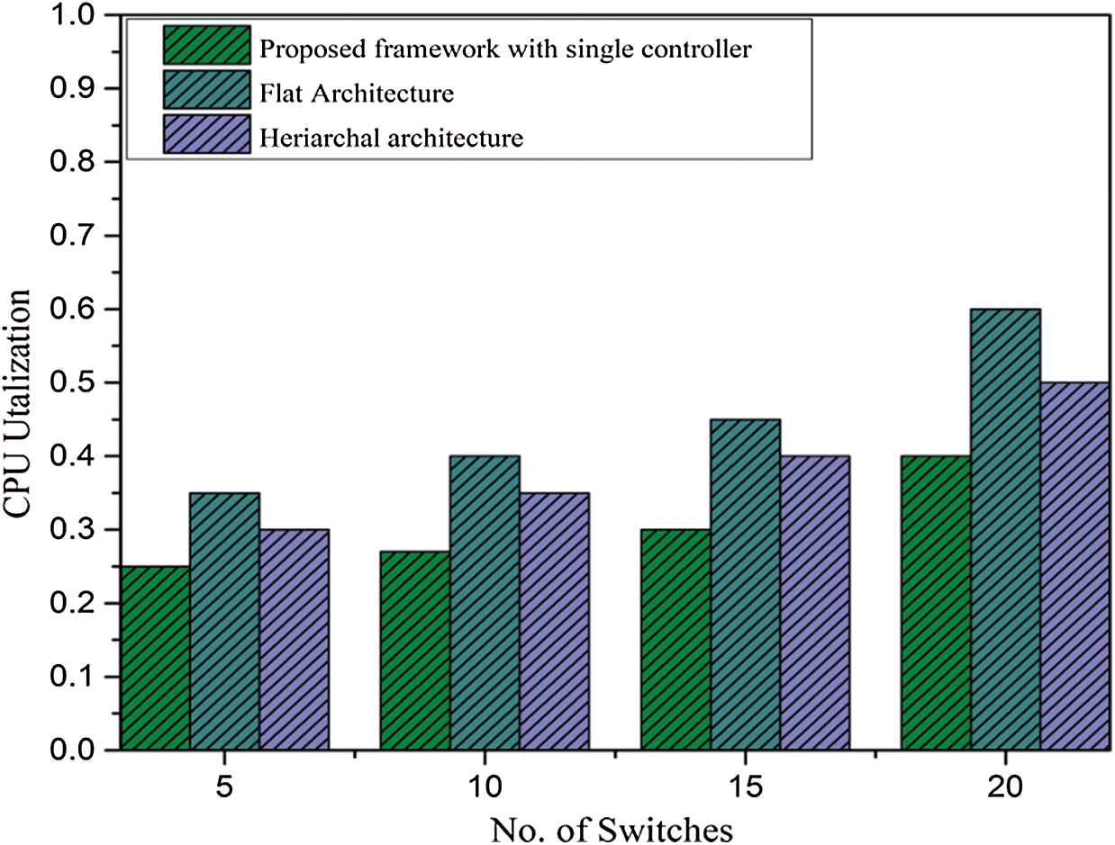
Figure 11: CPU utilization under the proposed framework and multiple-controller architecture
Our finding shows that the flat architecture framework is useful for network matrix performance compared with the hierarchical approach. The hierarchical approach is useful in the scalability of the network compared with single- and flat-controller architectures.
In this study, we enable the reachability across domains to avoid forwarding loops and packet drops without controller synchronization and select an optimized path through the ALTP scheme, which is based on a single-controller architecture for inter-domain flow. On the basis of the selection of the best path, we also formulate the problem of congestion among the selected inter-domain links, in which we include the dynamic cost load balancing strategy in our proposed framework to avoid congestion for the inter-domain flow on the selected inter-domain links. The extensive experiment result shows that our proposed methodology can minimize the flow setup latency and utilize controller workload through the existing solution. Moreover, we improve the throughput through link–load balancing under multiple domains. This work is limited in the control layer failure recovery. In the case of controller failure, the entire domain of the network will be disconnected from other domains. We will address these issues in future works.
Acknowledgement: The authors are grateful to the University of Malakand and University of Malaya for providing fund for this project.
Funding statement: The authors are grateful to the Taif University Researchers Supporting Project (number TURSP-2020/36), Taif University, Taif, Saudi Arabia. This research work was also partially supported by the Faculty of Computer Science and Information Technology, University of Malaya, under Postgraduate Research Grant PG035-2016A.
Conflicts of interest: The authors declare that they have no conflicts of interest to report regarding the present study.
1. S. Jain, A. Kumar, S. Mandal, J. Ong, L. Poutievski et al., “B4: Experience with a globally-deployed software-defined WAN,” ACM SIGCOMM Computer Communication Review, vol. 43, no. 4, pp. 3–14, 2013. [Google Scholar]
2. C.-Y. Hong, S. Mandal, M. Al-Fares, M. Zhu, R. Alimi et al., “B4 and after: Managing hierarchy, partitioning, and asymmetry for availability and scale in google’s software-defined WAN,” in Proc. of the 2018 Conf. of the ACM Special Interest Group on Data Communication, New York, NY, USA, pp. 74–87, 2018. [Google Scholar]
3. T. Y. Cheng and X. Jia, “Compressive traffic monitoring in hybrid SDN,” IEEE Journal on Selected Areas in Communications, vol. 36, no. 12, pp. 2731–2743, 2018. [Google Scholar]
4. O. Hohlfeld, J. Kempf, M. Reisslein, S. Schmid and N. Shah, “Scalability issues and solutions for software defined networks,” IEEE Journal on Selected Areas in Communications, vol. 36, no. 12, pp. 2595–2602, 2019. [Google Scholar]
5. M. Casado, M. J. Freedman, J. Pettit, J. Luo, N. McKeown et al., “Ethane: Taking control of the enterprise,” ACM SIGCOMM Computer Communication Review, vol. 37, no. 4, pp. 1–12, 2007. [Google Scholar]
6. N. McKeown, T. Anderson, H. Balakrishnan, G. M. Parulkar, L. Peterson et al., “OpenFlow: Enabling innovation in campus networks,” Computer Communication Review, vol. 38, no. 2, pp. 69–74, 2008. [Google Scholar]
7. I. Akyildiz, A. Lee, P. Wang, M. Luo and W. Chou, “A roadmap for traffic engineering in SDN-OpenFlow networks,” Comput Networks, vol. 71, no. 2, pp. 1–30, 2014. [Google Scholar]
8. L. Yu, J. Wu, A. Zhou, E. G. Larsson and P. Fan, “Massively distributed antenna systems with nonideal optical fiber fronthauls: A promising technology for 6G wireless communication systems,” IEEE Vehicular Technology Magazine, vol. 15, no. 4, pp. 43–51, 2020. [Google Scholar]
9. H. Cho, J. Park, J.-M. Gil, Y.-S. Jeong and J. H. Park, “An optimal path computation architecture for the cloud-network on software-defined networking,” Sustainability, vol. 7, no. 5, pp. 5413–5430, 2015. [Google Scholar]
10. P. Lin, J. Bi, S. Wolff, Y. Wang, A. Xu et al., “A west-east bridge based SDN inter-domain testbed,” IEEE Communications Magazine, vol. 53, no. 2, pp. 190–197, 2015. [Google Scholar]
11. M. Karakus and A. Durresi, “A survey: Control plane scalability issues and approaches in software-defined networking (SDN),” Computer Networks, vol. 112, no. 7, pp. 279–293, 2017. [Google Scholar]
12. Z. Guo, M. Su, Y. Xu, Z. Duan, L. Wang et al., “Improving the performance of load balancing in software-defined networks through load variance-based synchronization,” Computer Networks, vol. 68, no. 4, pp. 95–109, 2014. [Google Scholar]
13. Y. Yu, X. Li, X. Leng, L. Song, K. Bu et al., “Fault management in software-defined networking: A survey,” IEEE Communications Surveys & Tutorials, vol. 21, no. 1, pp. 349–392, 2018. [Google Scholar]
14. A. Dethise, M. Chiesa and M. Canini, “Prelude: Ensuring inter-domain loop-freedom iñ SDN-enabled networks,” in Proc. of the 2nd Asia-Pacific Workshop on Networking, Beijing, China, pp. 50–56, 2018. [Google Scholar]
15. X. Shi, Y. Li, H. Xie, T. Yang, L. Zhang et al., “An Openflow-based load balancing strategy in SDN,” Computers Materials & Continua, vol. 62, no. 1, pp. 385–398, 2020. [Google Scholar]
16. N. Khan, R. B. Salleh, Z. Khan and A. Koubaa, “Avoiding forwarding loop across multiple domains without controller synchronization in SDN,” in First Int. Conf. of Smart Systems and Emerging Technologies, Riyadh, KSA, pp. 122–127, 2020. [Google Scholar]
17. Y. Zhang, B. Zhu, Y. Fang, S. Guo, A. Zhange et al., “Secure inter-domain forwarding loop test in software defined networks,” IEEE Transactions on Dependable and Secure Computing, vol. 17, no. 1, pp. 162–178, 2017. [Google Scholar]
18. A. Tootoonchian and Y. Ganjali, “Hyperflow: A distributed control plane for openflow,” in Proc. of the Internet Network Management Conf. on Research on Enterprise Networking, San Jose, CA, pp. 1–3, 2010. [Google Scholar]
19. A. Shirmarz and A. Ghaffari, “Performance issues and solutions in SDN-based data center: A survey,” The Journal of Supercomputing, vol. 76, no. 10, pp. 7545–7593, 2020. [Google Scholar]
20. K. Phemius, M. Bouet and J. Leguay, “Disco: Distributed multi-domain SDN controllers,” in IEEE Network Operations and Management Symp., Krakow, pp. 1–2, 2014. [Google Scholar]
21. S. Hassas Yeganeh and Y. Ganjali, “Kandoo: A framework for efficient and scalable offloading of control applications,” in Proc. of the First Workshop on Hot Topics in Software Defined Networks, Helsinki, Finland, pp. 19–24, 2012. [Google Scholar]
22. P. Sun, Z. Guo, G. Wang, J. Lan, Y. Hu et al., “Marvel: Enabling controller load balancing in software-defined networks with multi-agent reinforcement learning,” Computer Networks, vol. 177, no. 5, pp. 107230, 2020. [Google Scholar]
23. A. El Kamel and H. Youssef, “Improving switch-to-controller assignment with load balancing in multi-controller software defined WAN (SD-WAN),” Journal of Network and Systems Management, vol. 28, no. 3, pp. 553–575, 2020. [Google Scholar]
24. H. Babbar, S. Rani, M. Masud, S. Verma, D. Anand et al., “Load balancing algorithm for migrating switches in software-defined vehicular networks,” Computers, Materials & Continua, vol. 67, no. 1, pp. 1301–1316, 2021. [Google Scholar]
25. M. R. Belgaum, S. Musa, M. M. Alam and M. M. Su’ud, “A systematic review of load balancing techniques in software-defined networking,” IEEE Access, vol. 8, pp. 98612–98636, 2020. [Google Scholar]
26. C. Hopps, Analysis of an equal-cost multi-path algorithm, document RFC 2992, pp. 1721–2070, Internet Engineering Task Force, 2000. [Google Scholar]
27. N. Katta, M. Hira, C. Kim, A. Sivaraman and J. Rexford, “Hula: Scalable load balancing using programmable data planes,” in SOSR '16: Symp. on SDN Research, Santa Clara, CA, USA, pp. 1–12, 2016. [Google Scholar]
28. F. Carpio, A. Engelmann and A. Jukan, “DiffFlow: Differentiating short and long flows for load balancing in data center networks,” in IEEE Global Communications Conf., Washington, DC, USA, pp. 1–6, 2016. [Google Scholar]
29. E. Akin and T. Korkmaz, “Comparison of routing algorithms with static and dynamic link cost in software defined networking (SDN),” IEEE Access, vol. 7, pp. 148629–148644, 2019. [Google Scholar]
30. W. Jiawei, Q. Xiuquan and N. Guoshun, “Dynamic and adaptive multi-path routing algorithm based on software-defined network,” International Journal of Distributed Sensor Networks, vol. 14, pp. 1–10, 2018. [Google Scholar]
31. J. Yan, H. Zhang, Q. Shuai, B. Liu and X. Guo, “HiQoS: An SDN-based multipath QoS solution,” China Communications, vol. 12, no. 5, pp. 123–133, 2015. [Google Scholar]
32. E. Akin and T. Korkmaz, “Rate-based dynamic shortest path algorithm for efficiently routing multiple flows in SDN,” in IEEE Int. Conf. on Communications, Shanghai, China, pp. 1–7, 2019. [Google Scholar]
33. T. S. Author, “Distributed inter-domain routing and load balancing in software defined networking (SDN),” M.S. thesis. Dept. Computer Sci., Ryerson Univ, Toronto, Ontario, Canada, 2019. [Google Scholar]
34. L. Zhu, M. M. Karim, K. Sharif, C. Xu, F. Li et al., “SDN controllers: A comprehensive analysis and performance evaluation study,” ACM Computing Surveys, vol. 53, no. 6, pp. 1–40, 2020. [Google Scholar]
35. Y. Liu, A. Hecker, R. Guerzoni, Z. Despotovic and S. Beker, “On optimal hierarchical SDN,” in IEEE Int. Conf. on Communications, London, UK, pp. 5374–5379, 2015. [Google Scholar]
36. Z. Latif, K. Sharif, F. Li, M. M. Karim, S. Biswas et al., “Dynamically optimized and load balanced path for inter-domain sdn communication,” IEEE Transactions on Network and Service Management, vol. 18, no. 1, pp. 331–346, 2020. [Google Scholar]
37. H. Zhou, C. Wu, Q. Cheng and Q. Liu, “SDN-LIRU: A lossless and seamless method for sdn inter-domain route updates,” IEEE/ACM Transactions on Networking, vol. 25, no. 4, pp. 2473–2483, 2017. [Google Scholar]
 | This work is licensed under a Creative Commons Attribution 4.0 International License, which permits unrestricted use, distribution, and reproduction in any medium, provided the original work is properly cited. |