DOI:10.32604/cmc.2021.016529
| Computers, Materials & Continua DOI:10.32604/cmc.2021.016529 | |
| Article |
Mobility Management in Small Cell Cluster of Cellular Network
Department of Computer Engineering, Jeju National University, Jeju, 63243, Korea
*Corresponding Author: Wang-Cheol Song. Email: philo@jejunu.ac.kr
Received: 04 January 2021; Accepted: 22 February 2021
Abstract: The installation of small cells in a 5G network extends the maximum coverage and provides high availability. However, this approach increases the handover overhead in the Core Network (CN) due to frequent handoffs. The variation of user density and movement inside a region of small cells also increases the handover overhead in CN. However, the present 5G system cannot reduce the handover overhead in CN under such circumstances because it relies on a traditionally rigid and complex hierarchical sequence for a handover procedure. Recently, Not Only Stack (NO Stack) architecture has been introduced for Radio Access Network (RAN) to reduce the signaling during handover. This paper proposes a system based on NO Stack architecture and solves the aforementioned problem by adding a dedicated local mobility controller to the edge cloud for each cluster. The dedicated cluster controller manages the user mobility locally inside a cluster and also maintains the forwarding data of a mobile user locally. To reduce the latency for X2-based handover requests, an edge cloud infrastructure has been also developed to provide high-computing for dedicated controllers at the edge of a cellular network. The proposed system is also compared with the traditional 3GPP architecture and other works in the context of overhead and delay caused by X2-based handover requests during user mobility. Simulated results show that the inclusion of a dedicated local controller for small clusters together with the implementation of NO Stack framework reduces the significant amount of overhead of X2-based handover requests at CN.
Keywords: Radio access network; mobility management; edge cloud computing; X2-based handover
It is highly expected that an extensive number of mobile devices will join the 5G network. The design of network architecture and 5G air interface is challenging and crucial in case of massive demand for applications and a variety of services [1]. The heterogeneous networks are often established to satisfy the cellular system and magnify the system capacity [2]. Small cells, macrocells, microcells, picocells and femtocells have been deployed in the same geographical region to build a heterogeneous network.
Fig. 1 shows that the small cell can be deployed standalone and co-exist with the macrocells [3]. Areas covered by small cells and macrocells are known as the Hot-spot while the Not-spot areas are covered by small cells only [4]. Only the basic network configuration involves with the CN in a Not-spot area that is less costly as compared to the Hot-spot [5]. This scenario leads the network operator to provide cellular coverage in rural areas, both indoor and outdoor [6]. In a Not-spot area, the numbers of small cells directly connect with one mobility management entity (MME). In this kind of configuration, the handover requests between the CN and small cells increase due to the initialization of frequent X2-based handover [7]. Therefore, this specific area of an access network needs the attention of the research community. The current Long-Term Evolution (LTE) architecture cannot reduce a massive amount of handover signaling because it executes an X2-based handover procedure in a rigid sequence of requests.

Figure 1: Illustration of hot-spot and not-spot area. (a) Hot-spot area (b) No-spot area
X2-Based handover permits a UE to maneuver from a serving cell to a neighbor cell and restores a replacement of Radio Resource Connection (RRC), whereas the Evolved Packet System (EPS) connection state is active. First, UE fetches the quality of signal strength and forwards it to the source small cell, then this small cell decides to act on a handover initiation procedure. Once the handover procedure is initiated, signals start trading between CN and a small cell for the bearer establishment. The UE context also transfers between the small cells.
The standard 3GPP LTE X2-based handover procedures from source small cells to targeted small cells are shown in Fig. 2. The handover starts when a UE submits a report of the targeted small cell to the source small cell. The targeted small cell sends back handover request ACK signal to the source small cell when handover decision and admission control complete by the source small cell and targeted small cell.
As soon as the targeted small cell receives the tunnel endpoint identifier (TEID) from a source small cell, it starts buffering downlink packets from SGW during the detachment of UE from the source small cell. UE detaches immediately from the source small cell after receiving the RCC connection reconfiguration request. Then the source small cell also sends the SN status transfer signal to the targeted small cell so that the targeted small cell can start forwarding data to UE after receiving the RCC connection reconfiguration completed signal from UE.

Figure 2: Sequence diagram of a typical 3GPP X2-based handover procedure
After the handover completes between the source and targeted small cells, the targeted small cell sends a signal to MME for path switching accordingly. MME sends a signal to SGW and PGW respectively for bearer modification after receiving the path switching request from the targeted small cell. SGW and MME receive the bearer modification responses respectively and the targeted small cell starts to receive downlink data from the SGW over a newly created bearer. The source small cell releases the UE context when it receives the UE context release signal from the targeted small cell.
Thus, a unique 5G network architecture design and devices are required. The answer to the question of how to fulfill this requirement is the use of network virtualization. Network virtualization provides a virtual unified and programmable interface. In the recent decade, various solutions have been proposed in the domains of Network Function Virtualization (NFV) and Software Defined Network (SDN). To name a few, a novel network architecture has been presented in [8]. These solutions comprise of cloud application, SDN controller, SDN-based transport network, SDN-based Cloud-RAN (C-RAN) and SDN-based core network. In a cloud infrastructure, a software-defined approach is used to separate the air interface via implementing the SDN on a Radio Access Network (RAN) [9]. An SDN architecture separates the data plane and control plane by pulling out the control logic from the traditional hardware. SDN controller uses the OpenFlow protocols and solely responsible to control the behavior of the network [10–12].
Meanwhile, a novel architecture of C-RAN has emerged in cellular communication technology using the cloud infrastructure. In C-RAN architecture, a Baseband Unit (BBU) shares the resources for baseband functionalities between Remote Radio Head (RRH) [13]. The combination of Information Centric Network (ICN), C-RAN and SDN play a significant role in attaining better communication and information management in the cellular network [14]. A centralized and distributed MME has been proposed in a joint scheme of C-RAN and SDN [15]. The authors have redesigned the architecture to improve the performance of mobility. However, it induces unnecessary processing delay during the execution of a handover procedure because it uses a traditionally rigid hierarchical sequence for a handover procedure.
A novel framework (NO Stack) has been derived from the hyper-cellular design that can reduce this handoff processing cost [16]. NO Stack framework works like SDN, which makes signals transmission better due to its easy signal instruction. SDN architecture consists of a control plane, data plane and management plane [17]. Efficient resource allocation is also accomplished in NO Stack with the help of a management plane to control the modules and push down the rigid stack. In a cellular network, the employment of the NO Stack on C-RAN introduces flexibility in communication. It also minimizes the traditional duration for a bearer creation. A network orchestrator has been used in this framework for network service orchestration by translating use cases to actual network function.
Another novel Mobile Edge Computing (MEC) technology initiative for the industry is also worth mentioning [18], which has been developed to accommodate a highly customized and user-centric service provisioning. This approach enables mobile network operatives to provide different APIs to third-party companies, which allows to access some salient features such as awareness of the current location and information relevant to the network context. All service instances of MEC should implement in a cloud for the RAN, irrespective of the implemented architecture for C-RAN.
This article proposes a distributed cloud architecture using the NO Stack framework to improve the X2-based handover procedure for mobility management. The main contributions to research for this work are summarized below.
• Major innovations and novelties of the proposed system include the placement of intelligence in the form of a Dedicated Small Cell Controller to the network’s edge at edge cloud straight to the Small Cell.
• The proposed system optimizes the clusters of small cells using a combination of a Global Network View (GNV) and the control functionality of the Global Controller (GC).
• Besides, the control functionalities of a Dedicated Cluster Controller (DCC) at the edge cloud also optimize the handover signals within a cluster via a Local Database (LDB).
• Likewise, DCC also maintains the associated forwarding information of UE among the small cells of a cluster in LDB that reduces path switching requests in CN.
• The high computing capability at the edge of a distributed cloud network minimizes the end-to-end delay between small cells cluster and computing resources.
• Additionally, the execution of the X2-based handover request at the edge cloud by DCC also reduces the latency in creating a dedicated bearer for a mobile user.
The rest of the paper is organized as follows: Section 2 pours some light on the background research related to the topic. Details of the proposed system are presented in Section 3. The use case analysis is conducted in Section 4. The details of an experimental setup and testing procedure are presented in Section 5. Section 6 evaluates the performance of the system. Section 7 concludes the paper and presents future work.
Several types of research have been directed to study the behavior of handover in the heterogeneous network. Mobility scenario, network throughput and overall latency are considered as a potential factor to evaluate the influence of the handover on the network performance. For example, few algorithms are proposed to improve the network performance [19,20]. Conversely, handover procedure analysis was ignored previously and concentrated on the simulation only. In this way, they can provide more complex understandings to improve network performance, such as predicting resources for vertical handovers.
While considering the vertical handover methodology to improve the mobility in the random installed small cells, the mobility model also studied and applied the distributed line segment technique on it. This line segment technique affects the count of vertical handover while a user moves around the small cells. In this regard, few scenarios concerning the model of mobility are presented in the article [21] which consist of the constant midpoint, isotropic mobility and constant pair scenario. However, they did not consider random mobility instead a movement in the straight line is considered in the randomly distributed small cells deployed area. But practically, the random user’s mobility behaviors are observed. It affects the measurements of a provided routing path for UE as well as measurements of turn. Therefore, another scientific methodology necessary to provide a solution to affects the count of vertical handover while considering the factor mentioned above.
Another algorithm proposes to improve the mobility scenario by tuning the parameters of mobility [22]. Then they have studied the influence of tuned parameters on the algorithm in order to improve network performance. Finally, a simulation was carried to assess and likened the influence of tuned parameters on the algorithm. Based on the results, the proposed algorithm has achieved better throughput when the pedestrians move in a circle and vehicles move in the rectangle.
The authors have studied two different techniques i.e., a supportive technique based on the base station of three successive cells in the user path and a handover hopping technique based on the approaching base station topology [23]. The first scheme, namely the cooperative scheme constantly provided the user with the two nearest BSs in the network. As far as the second technique concerns, three benchmarks are considered for skipping handovers (HO), which included the overall chord length and area of the cell and the distance from the cell edge. As an expected assessment of each benchmark, a threshold has been set. However, the user always bows down more towards HO skipping techniques.
The authors proposed a unique signal reduction approach at CN during the path switching process between clusters of small cells in the mobility scenario [24]. They used the typical LTE architecture and introduced the Small Cell Controller (SCC) on the RAN side into an existing Base Station (BS). This specialized dedicated SCC manages (MANAGED) all small cells in one cluster. During the mobility inside the local domain, SCC is also responsible for preserving the associated forwarding information for UEs. They compared their simulation results with the standardized 3GPP LTE system. Their results claimed that the proposed SCC based system achieved a significant reduction in signal overhead in CN.
The authors investigated the new evolving technique NO Stack RAN (NOS-RAN) in the RAN which is known as Not Only Stack (NO Stack) [25]. NO Stack simplified the signaling interactions among the different modules of LTE architecture by applying the SDN concept of flat protocol and centralized control logic. Authors have used the NS3 platform for the simulation of the proposed system and compared the generated results with the LTE-RAN in the term of signal overhead and delay budget during a handover procedure. The simulation results validated that the proposed NOS-RAN system reduces the considerable delay and signaling overhead during the path switching.
In another work, the author approved the programmability, flexibility and sustainability in the virtualized RAN (vRAN) using the concept of NO Stack [26]. While supporting customized services and multi-radio access technology (multi-RATs) to form a RAN slicing, they have deployed the network orchestration and RAN slice scheme in the proposed vRAN. The proposed vRAN also supported the virtualized network modules, therefore, some network procedures can be modified to customize the bearer establishment. This flexibility and modification of vRAN resulted in the reduction of signaling costs in the bearer establishment of up to 20% between the heterogeneous RATs. Alongside the bearer establishment, service response time is reduced up to 60% as well.
A mathematical model is proposed in this paper [27] to improve the vertical handover procedure in HetNet. They claimed that a critical role in the performance of the network to provide seamless mobility is played by vertical handover procedures. Due to the limitation of small cell properties, the network topology changes randomly and frequently, which is a big hurdle in analyzing the vertical handover procedure. A mathematical model is developed using stochastic geometry for the network layer to tackle the vertical handover procedure in the dynamic topology of small cells. Vertical handover procedures are studies under various mobility scenarios for the evaluation of the proposed system, then an exact value is set not only for the number of vertical handovers but also close to an approximation.
The study of related work convinces us that our proposed system contains novelty in the form of developing a distributed cloud network architecture using the NO Stack framework. The proposed edge cloud system decreases the X2-based handover signals load during path switching in the core network while considering the movement in intra-cluster and inter-cluster of small cells. The proposed system also provides edge computing for handling the X2-based handover signaling locally using the dedicated controller for each cluster at the edge cloud. The proposed system also reduces the number of signals at the core and edge cloud by using the transaction operation which performs like an asynchronous request.
In a distributed cloud network, a model of edge computing revolutionized the processing capability by bringing the computing resources at the edge of the telecommunication network [28]. This distributed infrastructure provides the facility to receive the UE’s request, analyze and perform required action if needed at the edge node instead of executing all the required actions at the central cloud. Hence, it reduces the number of requests to be performed at mobile CN while processing a substantial number of handover requests at the edge. Fig. 3 illustrates the proposed system architecture which consists of a device layer, edge layer and cloud layer. This architecture is designed based on the NO Stack framework to reduce the handover overhead in the core network. All layers are explained in detail under Subsection 3.1 and the proposed NO Stack framework is explained in Subsection 3.2.

Figure 3: Three-layered proposed architecture
In the device layer, the RRH represents a forwarding plane that sends handover signals to the edge layer for further processing. In the edge layer, each edge cloud manages one whole cluster of small cells and accepts the handover signals from the forwarding plane. All edge clouds hold BBUs, high-performance DCC and LDB for RRH’s data processing, handover request processing and keeping UE context data locally, which holds the information of UE related to an attached small cell. The edge layer presents a localized view while the cloud layer is responsible for monitoring and controlling the wide-area network. Only one central cloud exists in the cloud layer which contains the GNV, orchestrator and GC. This central cloud provides a broad network view of resource orchestration and global routing across the clusters of small cells.
The network operator achieves a programmability interface using DCC at the edge cloud and GC at the central cloud which offers the necessary network capabilities. At the edge layer, a DCC of each edge cloud connects to GC in the cloud layer and GC forwards their request to the corresponding DCC. An edge cloud can access a central cloud over the Internet to offload their computing workload, when they do not have functionality or computing resources to execute the request of UE locally, at the cost of communication latency and resource utilization overhead.
3.2 NO Stack Based Proposed Framework
The virtualization standard is adopted in the NO Stack framework for cellular networks. By acquiring this approach, the stack protocol pushes down vertically and the protocol layer is encapsulated as a module. The RAN is implemented using protocol [29] by an orchestrator because of the virtualization of a protocol module. The goal of implementing the virtualization technology into the cellular network is to decouple the user plane, control plane and management plane. Therefore, the NO Stack framework can provide abstraction, flexibility and intelligent features.
It can be seen from Fig. 4 that the management plane manages the control plane and user plane. Business Support System (BSS), Operation Support System (OSS) and orchestrator also operate at management plane to implement the customized services in the control plane and user plane. In the management plane, the orchestrator creates, delete and updates the virtual machines which keep the virtualized network functions. In the proposed system, the management plane also manages the user plane as well, therefore, the organization and configuration network elements (NEs) in the user plane are provided by the management plane.

Figure 4: Components of the proposed three-layer architecture
The existence of centrally localized control functionalities in the control plane of the proposed architecture provides control over all clusters. The management plane also orchestrates resources in the control plane by using the exposed open interface. In the control plane, GC comprises the functionalities of PCRF, MME and DNS, etc. The authors of the NO Stack framework have explained the specifications and architecture of GC in detail [30]. GC also runs inside the virtual machine with a variety of services and functions. For example, when the user starts to move around the small cells and a required handover is needed for bearer establishment then GC invokes the functionality of mobility management to execute a handover request. The classification of required service for every invoked functionality can be achieved by selecting and combining them accordingly. The data transmission and processing functionalities are programmable in the user plane therefore latency between the control plane and user plane can be bargained remarkably. The traditional GW functionality has been removed in the framework with xGW which contains the flow table gateway (GW).
At the management level, the orchestrator provides all instructions of configurations for connectivity among all the modules in the user plane in the form of a flow connection through the flow table. Therefore, it makes it clear to orchestrate each module separately. DCC is also added at the access network with few mobility management functionalities to decrease the X2-based handover requests at CN. DCC could be deployed standalone and as an integral part of BBU but for the sake of keeping the standard architecture of a cellular network, DCC is realized as a part of the BBU and control a whole small cell’s cluster. DCC forwards the Packet Data Units (PDUs) to the mobile user through LDB because LDB stocks the statistics of the complete small cell’s cluster and the attachment of UE with the small cell.
GNV has been introduced as a database in the proposed system and supplies complete information about the control and user planes. The management plane fetches the information from the GNV of an access network and controls them by centrally virtualizing in a virtual resource pool. GNV also stores the statistics of NEs configuration and makes it available for the management plane to configure the desired modules. GNV also stores information about the attachment of a UE to a small cell. As shown in Figs. 5a and 5b, as soon as UE moves across the cluster of small cells, GC is invoked by DCC to execute the X2-based handover procedure. While the X2-based handover procedure is executed by DCC when a user moves inside the cluster of small cells, respectively. The details of these scenarios are explained in Subsections 4.1 and 4.2, respectively.

Figure 5: X2-based handover demonstration. (a) Intra-cluster (b) Inter-cluster
Fig. 4 shows that the DCC is directly connected to GC and xGW. The standard interfaces [31] are used to create the following connections among those entities. All the small cells of a cluster and the neighboring small cells depicted in Fig. 3 are interconnected through the X2 interface [32]. Although the NO Stack framework is still under development, some use cases based on NO Stack are studied in this section. In the selected use cases, only one small cell from each cluster connects to MME in the core network, therefore we can only analyze the X2-based handover use cases in this arrangement.
4.1 Intra-Cluster X2-Based Handover Procedure Using DCC
Whenever UE moves inside the cluster, DCC invokes the X2-based handover procedure as shown in Fig. 6. DCC updates the identity of a targeted cell in the LDB and GNV DB. DCC based BBU uses this data from LDB to forward the data to the UE. The data stored in the GNV DB is used for the execution of a handover procedure when UE moves across the cluster. A signal between DCC and LDB is not drawn in the sequence diagram because there is no network signal involved while updating the LDB as it resides inside the same BBU with DCC.

Figure 6: Sequence diagram of intra-cluster X2-based handover procedure
Every time the UE crosses the premises of a small cell within the cluster, UE informs the report of a targeted small cell to DCC rather than source small cell. Then subsequently DCC decides and prepares a plan for the handover procedure. Most importantly, the DCC manages the LDB for tracking the association of UE with the small cells.
If the targeted small cell resides inside the same cluster monitor by DCC then DCC performs two tasks simultaneously. Firstly, DCC forwards the report to source BUU for the execution of handover and secondly, it forwards TEID to targeted BBU.
Then handover command, SN status transfer and handover confirmation follow the standard 3GPP procedure.
Finally, DCC also performs two tasks simultaneously and immediately when it gets notified by the targeted BBU about the completion of the handover procedure whilst the targeted BBU gets a network of UE arrival. DCC commands source BBU to release the UE context and updates the information of the UE context in GNV DB. Hence, the message signals did not forward to CN for path switching, instead, DCC transferred the inter-node UE context from the source to the target small cell for X2-based handover.
4.2 Inter-Cluster X2-Based Handover Procedure Using DCC and GC
DCC invokes GC for the X2-based handover procedure whenever UE moves across the cluster as shown in Fig. 7. GC updates the identity of a targeted cell in the LDB and GNV DB. As mentioned earlier, the LDB data is used by DCC-based BBU to forward data to the UE, but the data stored in GNV DB contains the global information of UE attachment with the small cell. GC uses data from GNV DB for the execution of a handover procedure when UE moves across the cluster.

Figure 7: Sequence diagram of inter-cluster X2-based handover procedure
The process of reporting of the targeted small cell follows the same procedure while considering the scenario of handover execution across the cluster. If the targeted small cell does not reside inside the same cluster monitored by DCC then DCC erases the UE information from LDB and forwards the report of a targeted small cell to GC. GC performs two tasks simultaneously after receiving the path switching command from the DCC. Firstly, GC forwards the report to source BUU for the execution of handover and secondly, it forwards TEID to targeted BBU.
The handover execution follows the standard 3GPP procedure.
Once a targeted BBU notifies the GC about the completion of a handover procedure while the targeted BBU gets a network of UE arrival, GC performs four tasks instantaneously for handover completion. GC instructs source BBU to release UE context and creates downlink bearer from xGW to targeted BBU by allocating TEID of targeted BBU to xGW, updates the information of the UE context in GNV DB and updates UE context in a targeted DCC.
4.3 LTE-RAN vs. Proposed System
DCC is equipped to issue instructions to BBUs simultaneously and manages the inter-cluster handover locally as explained in Subsection 4.1. Similarly, GC is also qualified to send an instruction to MME, xGW and DCC simultaneously and managing the handover globally as explained in Subsection 4.2. In this way, each simultaneous transaction can be considered as one action of time utilization. Therefore, the proposed system reduces the handover delay by performing fewer operations as compared to legacy X2-based handover operations for both scenarios. The freedom in NEs leads to make xGW, which is an integrated control logic of SGW and PGW. This innovation has significantly reduced delays by enabling intra-communication between SGW and PGW rather than flow operations.
The simultaneous processing approach in the proposed system does not follow the layer by layer approach for handover process execution. Therefore, the proposed system reduces the number of signals at CN during the handover procedure. The scenarios explained in Subsections 4.1 and 4.2 consume six and seven signals respectively, whereas the traditional X2-based handover of procedure 3GPP consumes 13 signals. In this way, the proposed system eliminates the 54% redundant signal when a user moves within the cluster and eliminates the 46% redundant signal when a user moves across the clusters.
Fig. 8 shows a distributed cloud architecture testbed, which is created to support the proposed X2-based handover procedures. In the proposed system, VNFs are compulsory which makes the user plane and control plane programmable. Therefore, Open Source MANO (OSM) [33] is installed in the central cloud to manage the desired VNFs in the user plane and control plane [34]. By taking the leverage of OpenStack Training Lab [35], a three-node architecture is deployed to create Network Function Virtualized Infrastructure (NFVI). Each node represents a cloud and contains three network interfaces to communicate with each other. All nodes communicate with each other through a management network, also all nodes are connected to the internet through a public network and the interfacing with VMs is delivered by the provider network. Only one machine has been used for a complete virtualized setup. Central cloud and edge clouds are created in the same machine using Oracle VirtualBox VMs. The host machine contains 252 GB RAM, 2.5 TB SSD, 2.10 GHz 32-cores processor, and Ubuntu 18 as an OS.
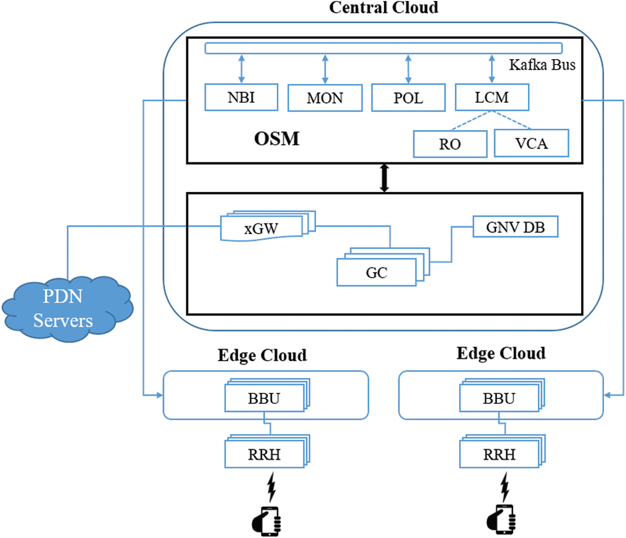
Figure 8: Virtualized distributed cloud-based experimental setup
OSM has the capability of Network Services (NS) configuration, VNF orchestration, monitoring of VNFs health and network resources. The VNF Descriptor (VNFD) represents the information model (IM) of OSM to elaborate the details of a VNF. VNFD is divided into three parts, namely connection point, basic information, and Virtual Data Unit (VDU) information respectively. The Network Services Descriptor (NSD) represents the information model (IM) of OSM to elaborate the configuration of VNFD for the creation of a network service. The NSD is divided into three parts, namely Virtual Link Descriptor (VLD) Information, Basic Information, Connection Point, and VNF Descriptor (VNFD) Information.
We have extended our previous work [36] to create the testbed, where each cluster contains 3 RRHs and 3 vBBUs deployed in the edge cloud. In [37], the authors have presented virtualized EPC and C-RAN integration using the cloud with the aid of OAI and OSM. Based on their split functionality, we have extracted the vBBU modules from openair-rru branch of OAI software to make changes according to the proposed framework and deploy them to create a cluster of small cells in two different edge clouds. We have also extracted the CN modules from [38] branch to develop the GC and xGW modules of the proposed framework. After modifying these modules, we have made bootable VNF images of virtual machines using Oracle Virtual Box so that the orchestrator can use it to deploy and configure these VNFs on distributed clouds. All RRHs are deployed using the Software Defined Radio (SDR) Universal Software Radio Peripheral (USRP) B210 10 dbm transmitting power. Distributed Unit (DU) is a signal processing part of RRH which deploy close to the antennas. Each DU runs on the Intel Core i5-7400 CPU@3.00 GHz system which contains 16 GB RAM. The RRH connects with DU using the high-speed USB 3.0 which possesses 5.0 Gbit/s bus-power. The connection of RRH with vBBU and vBBU with vEPC uses the 1 Gbit/s physical interface. At least 2 UEs are required for the demonstration of X2-based handover, therefore 2 mobile phones are used which are customized using the programmable SIM and configured with PLMN ID and IMSI etc. All these pieces of information are also parameterized in the vEPC [38]. Besides, OSM also provides the telemetry service for the deployed VNFs and NS on the NFVI. Each VNFD needs to be configured for the desired monitored parameters from NFVI and VNF instances, for example, network stats, CPU, or RAM utilization etc. To monitor the desired metrics, we have configured NFVI (OpenStack with Ceilometer). OSM also stores the monitored metrics in Prometheus and these metrics can be visualized using Grafana.
6 Evaluation of Proposed System
The required time for handover execution can be split into the following categories: before handover initialization, handover preparation, handover execution, handover completion and upper bound margin. The time before initialization handover request is spent on searching and identifying the target small cell. Similarly, handover preparation time is spent on the state transition of UE from RRC connected to RRC idle. During this transition, the source small cell sends RRC connection reconfiguration to UE. This execution time also includes the X2-AP transport and processing. The handover execution time is used in sending an RRC connection reconfiguration-completed message to grant access to an uplink resource. In the handover completion time, UE does not experience any delay because it is already in a connected state with a targeted small cell. The upper bound margin delay is specifically reserved for the implementation. The proposed system implements the transaction operation using the asynchronous approach, therefore, the upper bound margin reduces exponentially. The proposed C-RAN deployment scenario also reduces the transport delay compared to negligible because no transport network medium exists among the BBUs and they share infrastructure that simplifies X2-based messages internally.
Fig. 9 shows the two types of delay budget that occur during X2-based handover request and the creation of the required dedicated bearer during the UE movement between two small cells. One delay consists of handover preparation time and handover execution time in the intra-cluster movement. There is no delay involved in creating a dedicated bearer because DCC controls the X2-based handover locally. The second delay consists of handover preparation time, handover execution time, and handover completion for the inter-cluster movement. In this scenario, the extra delay is also added due to signaling between small cells to GC and GC to xGW. Due to a new design rule xGW, the delay between SGW and PGW has been ignored during dedicated bearer creation.

Figure 9: X2-based handover procedure delay budget
It can also be seen in Fig. 9 that the major handover delay time occurs during the handover preparation and handover execution. The delay measurement of handover preparation is exceptionally low when UE is in a connected state and sends a measurement report to the source small cell for the new connection with the targeted small cell. A major delay occurs when the state of UE moves from idle state (after reception of RCC reconfiguration message) to connected state (after complete reception of RCC reconfiguration message at target small cell).
The proposed system reduces the delay up to 65 ms in the intra-cluster movement while a reduction up to 40 ms delay in the inter-cluster movement is achieved. Due to the rapid innovation of technologies, the processing delays and processing capacity of each NE are also clearly improving. Therefore, X2-based handover delay can be reduced more significantly. In the traditional LTE system, MME, SGW and PGW bear signaling overhead in the CN while using the proposed system GC and xGW bear the signaling overhead in CN. The handover overhead depends on the number of bytes handle by each NE. The LTE system handles the 373 bytes of data during a handover procedure [39]. The proposed system cut down the lots of data rate in intra-cluster handover up to 150 bytes and in inter-cluster up to 275 bytes.
The handover overhead is held up by each NE in inter-cluster and intra-cluster as shown in Fig. 10. Fig. 10a reveals that the handover overhead increases in CN when a user moves inter-cluster. Fig. 10b depicts that when UE moves intra-cluster, the signaling overhead in CN decreases by up to 100%. Fig. 10c shows that in the LTE system, a target small cell keeps up the utmost burden related to other NE. Due to the inclusion of mobility functionalities in DCC and GC by the proposed system, overhead in the edge network increases but decreases in the CN. As compared to the LTE system, other NE holds up less load of the overhead in the proposed system. Even though most of the burden of handover overhead is endured by GC and DCC in the proposed system, yet the processing abilities of GC and DCC are still manageable because these VNFs run in virtual machines.

Figure 10: X2-based handover procedure’s overhead budget in percentage. (a) Inter-cluster mobility for the proposed system. (b) Intra-cluster mobility for the proposed system. (c) 3GPP LTE system
A few comparisons of the delay budget and signaling overhead with some most relevant works are presented in Fig. 11. The first graph shows the time spent on one complete handover procedure and the second graph shows the signal overhead at the CN. The implementation environments of selected related works are different from each other, therefore, the establishment of one standard of delay budget for comparison in the first graph is not possible. Considering the aforementioned reason, each related work and the proposed system is compared with the legacy 3GPP LTE system separately in the first graph. The last two bars in both graphs represent the two scenarios (Intra-cluster and Inter-cluster HO) of the proposed system. It can be seen in both comparison graphs that the proposed system performed quite well as compared to both systems [25,26] while considering the Intra-cluster HO. While considering the Inter-cluster HO, the performance of the proposed system is better than the system [24] but not good as compared to systems [25,26]. But the overall average HO delay and overhead of the proposed system are better than other systems. Hence, the X2-based handover overhead and delay is decreased incredibly as compared to the LTE system by the proposed system.

Figure 11: A component details of the proposed three-layer architecture
In this work, the proposed system makes the C-RAN programmable to improve the procedure of X2-based handover execution. The control functionality of GC at CN in the proposed architecture provides network enhancement across the clusters via GNV. Similarly, the control functionality of DCC in the edge cloud provides the enhancement across the cluster of small cells via an LDB. The proposed system simplifies the handover signaling flow by implementing NO Stack based transaction operation. A study of experimental simulation results has explored the benefits related to mobility in inter-cluster and intra-cluster of small cells. This study symbolizes the expected performance improvement using the proposed solution. While creating the dedicated bearer during X2-based handover, a significant reduction in delay and overhead is achieved in CN as compared to traditional LTE.
The proposed virtualized multi-tenant and cloud-enabled infrastructure of small cells cluster convey new prospects to the business community. Traditionally, the inflation of handover requests at the CN requires additional dedicated network hardware that increases capital expenditures (CAPEX) and operating expenses (OPEX). Conversely, the proposed system virtualizes additional network functions in the existing general-purpose hardware when handover requests at the CN increase and hence reduces CAPEX and OPEX.
Although, the proposed system will empower the next-generation 5G network with the scalable capacity to satisfy various KPIs for machine-type communication. The position of BBU which contains the DCC in the small cells cluster, variable coverage of small cell footprint and dynamic user velocity affect the X2-based handover overhead in CN. But we have assumed the position in the middle of the cluster and fixed coverage of small cell footprint and constant user velocity. The inclusion of data orchestration in the central as well as edge clouds, asynchronous processing and segregation of function granularity increase the complexity of an X2-based handover procedure as compared to the 3GPP LTE standard.
The overall proposed architecture leads toward the integration of ETSI NFV and 3GPP LTE standards. A careful study of the privacy and security of several tenants should be conducted. Besides, a study of performance and management also needs to be considered. Also, a Blockchain will be considered in future work for the creation of a secure and on-demand distributed edge cloud network.
Acknowledgement: This research was supported by the MSIT (Ministry of Science and ICT), Korea, under the ITRC (Information Technology Research Center) support program (1ITP-2021-2017-0-01633) supervised by the IITP (Institute for Information & communications Technology Planning & Evaluation). This research was supported by Basic Science Research Program through the National Research Foundation of Korea (NRF) funded by the Ministry of Education (NRF-2016R1D1A1B01016322).
Funding Statement: The authors received no specific funding for this study.
Conflicts of Interest: The authors declare that they have no conflicts of interest to report regarding the present study.
1. Q. Duan, N. Ansari and M. Toy, “Software-defined network virtualization: An architectural framework for integrating SDN and NFV for service provisioning in future networks,” IEEE Network, vol. 30, no. 5, pp. 10–16, 2016. [Google Scholar]
2. 3GPP, “Mobility enhancements in heterogeneous networks,” 2012. [Online]. Available: http://www.3gpp.org/. [Google Scholar]
3. 3GPP, “Scenarios and requirements for small cell enhancements,” 2014. [Online]. Available: http://www.3gpp.org/. [Google Scholar]
4. NGMN, “Small cell backhaul requirements,” 2012. [Online]. Available: https://www.ngmn.org/publica-tions/ngmn-whitepaper-small-cell-backhaul-requirements.html. [Google Scholar]
5. Small Cell Forum, “Small cells-what’s the big idea?,” 2012. [Online]. Available: https://www.yumpu.com/en/document/read/3352328/small-cells-aeur-whats-the-big-idea-small-cell-forum. [Google Scholar]
6. Ofcom, “Ofcom unveils plans for 4G auction of the airwaves,” 2012. [Online]. Available: https://www.ofcom.org.uk/about-ofcom/latest/media/media-releases/2012/ofcom-unveils-plans-for-4g-auction-of-the-airwaves. [Google Scholar]
7. Ziyu Xiao and Harry Perros, “Response time of the S1 and X2 handover procedures between (H) eNBs in a virtualized environment,” 2015. [Online]. Available: https://people.engr.ncsu.edu/hp/papers/ZiYu1.pdf. [Google Scholar]
8. Z. Ma, Z. Zhang, Z. Ding, P. Fan and H. Li, “Key techniques for 5G wireless communications: Network architecture, physical layer and MAC layer perspectives,” Science China Information Sciences, vol. 58, pp. 1–20, 2015. [Google Scholar]
9. Z. Zaidi, V. Friderikos and M. A. Imran, “Future RAN architecture: SD-RAN through a general-purpose processing platform,” IEEE Vehicular Technology Magazine, vol. 10, no. 1, pp. 52–60, 2015. [Google Scholar]
10. S. H. Yeganeh, A. Tootoonchian and Y. Ganjali, “On scalability of software-defined networking,” IEEE Communications Magazine, vol. 51, no. 2, pp. 136–141, 2013. [Google Scholar]
11. J. Ali and B. Roh, “An effective hierarchical control plane for software-defined networks leveraging TOPSIS for end-to-end QoS class-mapping,” IEEE Access, vol. 8, pp. 88990–89006, 2020. [Google Scholar]
12. J. Ali and B. Roh, “Quality of service improvement with optimal software-defined networking controller and control plane clustering,” Computers, Materials & Continua, vol. 67, no. 1, pp. 849–875, 2021. [Google Scholar]
13. A. Checko, H. L. Christiansen, Y. Yan, L. Scolari, G. Kardaras et al., “Cloud RAN for mobile networks—A technology overview,” IEEE Communications Surveys & Tutorials, vol. 17, no. 1, pp. 405–426, 2015. [Google Scholar]
14. C. Yang, Z. Chen, B. Xia and J. Wang, “When ICN meets C-RAN for HetNets: An SDN approach,” IEEE Communications Magazine, vol. 53, no. 11, pp. 118–125, 2015. [Google Scholar]
15. I. Al-Samman, A. Doufexi and M. Beach, “A proposal for hybrid SDN C-RAN architectures for enhancing control signaling under mobility,” in Proc. IEEE 84th Vehicular Technology Conf. Fall, Montreal, QC, Canada, pp. 1–6, 2016. [Google Scholar]
16. J. Zeng, L. Rong and X. Su, “NO stack: A software-defined framework for 5G mobile network,” in Proc. 23rd Int. Conf. on Telecommunications, Thessaloniki, Greece, pp. 1–5, 2016. [Google Scholar]
17. S. H. Yeganeh, A. Tootoonchian and Y. Ganjali, “On scalability of software-defined networking,” IEEE Communications Magazine, vol. 51, no. 2, pp. 136–141, 2013. [Google Scholar]
18. Y. C. Hu, M. Patel, D. Sabella, N. Sprecher and V. Young, “Mobile Edge Computing A key technology towards 5G,” 2015. [Online]. Available: https://www.etsi.org/images/files/etsiwhitepapers/etsi_wp11_mec_a_key_technology_towards_5g.pdf. [Google Scholar]
19. M. M. Hasan, S. Kwon and J. H. Na, “Adaptive mobility load balancing algorithm for LTE small-cell networks,” IEEE Trans. Wireless Commun., vol. 17, no. 4, pp. 2205–2217, 2018. [Google Scholar]
20. M. M. Hasan, S. Kwon and S. Oh, “Frequent-handover mitigation in ultra-dense heterogeneous networks,” IEEE Trans. Veh. Technol., vol. 68, no. 1, pp. 1035–1040, 2019. [Google Scholar]
21. M. S. Girija, M. S. Kayathri and M. S. Meena, “Analysis of shortest path routing for large multi-hop wireless networks,” Int. J. Eng. Technol., vol. 7, no. 3.10, pp. 59, 2018. [Google Scholar]
22. S. Oh, H. Kim and Y. Kim, “User mobility impacts to mobility load balancing for self-organizing network over LTE system,” in Proc. 14th Int. Conf. Adv. Trends Radioelectron., Telecommun. Comput. Eng., Lviv-Slavske, Ukraine, pp. 1082–1086, 2018. [Google Scholar]
23. E. Demarchou, C. Psomas and I. Krikidis, “Mobility management in ultra-dense networks: Handover skipping techniques,” IEEE Access, vol. 6, pp. 11921–11930, 2018. [Google Scholar]
24. J. S. Thainesh, N. Wang and R. Tafazolli, “Reduction of core network signalling overhead in cluster based LTE small cell networks,” in Proc. IEEE 20th Int. Workshop on Computer Aided Modelling and Design of Communication Links and Networks, Guildford, UK, pp. 226–230, 2015. [Google Scholar]
25. X. Zheng, L. Ge, Y. Tang, B. Liu, J. Zeng et al., “NO stack for enhancing mobility performance in 5G radio access network,” in Proc. 2018 Int. Conf. on Computer, Information and Telecommunication Systems, pp. 1–5, 2018. [Google Scholar]
26. J. Zeng, X. Su, J. Gong, L. Rong and J. Wang, “A 5G virtualized RAN based on NO stack,” China Communications, vol. 14, no. 6, pp. 199–208, 2017. [Google Scholar]
27. T. M. Duong and S. Kwon, “Vertical handover analysis for randomly deployed small cells in heterogeneous networks,” IEEE Transactions on Wireless Communications, vol. 19, no. 4, pp. 2282–2292, 2020. [Google Scholar]
28. A. Rafiq, M. Afaq and W. C. Song, “Mobility performance enhancement in small cells cluster of 5G network: A handover overhead reduction approach,” in Proc. 21st Asia-Pacific Network Operations and Management Symp., Daegu, Korea (Southpp. 373–376, 2020. [Google Scholar]
29. X. Mi, Z. Tian, X. Xu, M. Zhao and J. Wang, “NO stack: A SDN-based framework for future cellular networks,” in Proc. Int. Symp. on Wireless Personal Multimedia Communications, Sydney, NSW, Australia, pp. 497–502, 2014. [Google Scholar]
30. J. Zeng, X. Su, J. Gong, L. Rong and J. Wang, “5G virtualized radio access network approach based on NO Stack framework,” in Proc. IEEE Int. Conf. on Communications, Paris, pp. 1–5, 2017. [Google Scholar]
31. ETSI, “S1 application protocol (S1AP),” 2015. [Online]. Available: https://www.etsi.org/deliver/etsi_ts/136400_136499/136413/12.04.00_60/ts_136413v120400p.pdf. [Google Scholar]
32. ETSI, “X2 general aspects and principles,” 2015. [Online]. Available: https://www.etsi.org/deliver/etsi_ts/136400_136499/136420/12.01.00_60/ts_136420v120100p.pdf. [Google Scholar]
33. ETSI, “OSM Quickstart,” 2020. [Online]. Available: https://osm.etsi.org/docs/user-guide/01-quickstart. html. [Google Scholar]
34. A. Rafiq, A. Mehmood, T. A. Khan, K. Abbas, A. Muhammad et al., “Intent-based end-to-end network service orchestration system for multi-platforms,” Sustainability, vol. 12, no. 7, pp. 2782, 2020. [Google Scholar]
35. OpenStack, “Training Labs,” 2020. [Online]. Available: https://wiki.openstack.org/wiki/Documentation/ training-labs. [Google Scholar]
36. K. Abbas, M. Afaq, T. K. Ahmed, A. Rafiq, Javed Iqbal et al., “An efficient SDN-based LTE-WiFi spectrum aggregation system for heterogeneous 5G networks,” Trans. Emerging Tel. Tech., pp. e3943, 2020. [Google Scholar]
37. A. F. Ocampo, T. Dreibholz, M. Fida, A. Elmokashfi and H. Bryhni, “Integrating cloud-RAN with packet core as VNF using open ssurce MANO and openairinterface,” in Proc. of the 45th IEEE Conf. on Local Computer Networks, New South Wales (Australia2020. [Google Scholar]
38. EPC VNFD, [Online]. Available: https://github.com/simula/5gvinni-oai-ns. [Google Scholar]
39. 3GPP, “Feasibility study for UTRA and UTRAN,” 2014. [Online]. Available: https://www.3gpp.org/ftp//Specs/archive/25_series/25.912/. [Google Scholar]
 | This work is licensed under a Creative Commons Attribution 4.0 International License, which permits unrestricted use, distribution, and reproduction in any medium, provided the original work is properly cited. |