DOI:10.32604/cmc.2021.017418
| Computers, Materials & Continua DOI:10.32604/cmc.2021.017418 | |
| Article |
Real-Time Dense Reconstruction of Indoor Scene
1Institute of Mechanics, North China University of Water Resources and Electric Power, Zhengzhou, 450011, China
2IT Fundamentals and Education Technologies Applications, University of Information Technology and Management in Rzeszow, Rzeszow, 100031, Poland
*Corresponding Author: Jinxing Niu. Email: njx.mail@163.com
Received: 29 January 2021; Accepted: 03 March 2021
Abstract: Real-time dense reconstruction of indoor scenes is of great research value for the application and development of service robots, augmented reality, cultural relics conservation and other fields. ORB-SLAM2 method is one of the excellent open source algorithms in visual SLAM system, which is often used in indoor scene reconstruction. However, it is time-consuming and can only build sparse scene map by using ORB features to solve camera pose. In view of the shortcomings of ORB-SLAM2 method, this article proposes an improved ORB-SLAM2 solution, which uses a direct method based on light intensity to solve the camera pose. It can greatly reduce the amount of computation, the speed is significantly improved by about 5 times compared with the ORB feature method. A parallel thread of map reconstruction is added with surfel model, and depth map and RGB map are fused to build the dense map. A Realsense D415 sensor is used as RGB-D cameras to obtain the three-dimensional (3D) point clouds of an indoor environments. After calibration and alignment processing, the sensor is applied in the reconstruction experiment of indoor scene with the improved ORB-SLAM2 method. Results show that the improved ORB-SLAM2 algorithm cause a great improvement in processing speed and reconstructing density of scenes.
Keywords: Scene reconstruction; improved ORB-SLAM2; direct method; surfel
Scene reconstruction is a research focus in the field of computer vision. It has a wide applications in indoor positioning and navigation, semantic maps, augmented reality, virtual reality, cultural relics protection, etc. [1–5]. In recent years, some new RGB-D sensors (such as Kinect V1, Kinect V2, Realsense SR300, Realsense D415) are used for the 3D (three dimensional) reconstruction of indoor scenes, and new algorithms are successively produced (such as KinectFusion [6], DynamicFusion [7], ElasticFusion [8], Fusion4D [9], BundleFusion [10]). KinectFusion method is limited to small scenes, which cannot be used for moving, large, or deformation scenes. DynamicFusion method can be used in the reconstruction of non-rigid dynamic scenes. BundleFusion method is used for the reconstruction of a complete large indoor scene. Considering the density and accuracy of reconstruction of indoor scene map, it is often to use GPU accelerator, or even multiple GPUs for parallel acceleration, which limits its application in some situation [11].
In recent years, SLAM (simultaneous localization and mapping) technology is often used for 3D reconstruction of indoor scenes combined with RGB-D sensors, such as RGB-D SLAM v2 [12], ORB-SLAM2 [13] and others. RGB-D SLAM V2 is a 3D reconstruction solution based on the Kinect V1 sensor that can be used for robots, aircraft, and handheld equipment. It performs 3D reconstruction of the scene through operations such as feature point matching and graph optimization. GPU acceleration calculations are needed to obtain real-time reconstruction. ORB-SLAM2 is an upgraded version carried out by Raul Mur-Artal based on ORB-SLAM [14] for real-time reconstruction of monocular camera, which can be also used for binocular camera and RGB-D sensor. The reconstruction point cloud of 3D scene is relatively sparse by ORB-SLAM2 based on ORB feature. It will affect the accuracy of 3D reconstruction of indoor scene, and may even cause holes in the generated 3D model.
This article proposes an improved ORB-SLAM2 method and applies it into the real-time reconstruction of indoor scenes. It can promote the 3D reconstruction accuracy of indoor scenes and can reduce the running time simultaneously.
Intel Realsense D415 RGB-D sensor is used to obtain the RGB and depth image of indoor scene. It needs to be calibrated to obtain the internal and external parameters of the cameras. Fig. 1 shows the Realsense D415 RGB-D sensor and its calibration experiment.
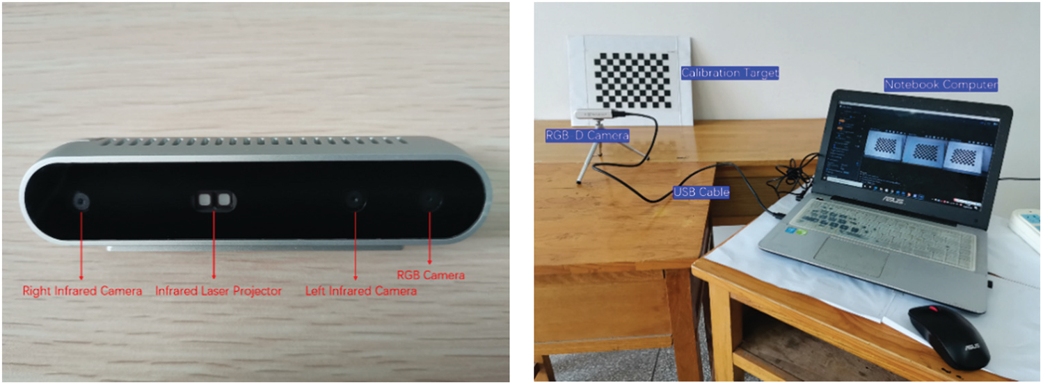
Figure 1: Realsense D415 RGB-D sensor (left), RGB-D sensor calibration experiment (right)
There are three coordinates system including the pixel coordinate system, the camera coordinate system, and the world coordinate system, see Fig. 2. Camera calibration is to calculate the internal and external parameters. Internal parameters are camera parameters. External parameters are transformation relationship between different coordinates. Assuming that the left infrared camera is the reference camera and its optical centre is located at the origin of the world coordinate system, the internal parameters and external parameters of left infrared camera, right infrared camera and RGB camera can be calculated.
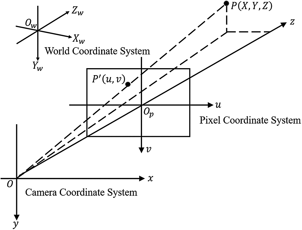
Figure 2: Three coordinate systems
A point in pixel coordinate can be calculated by formula (1), where K is the internal parameter matrix of the camera, M is the external parameter matrix of the camera. The external parameters of the right infrared camera and RGB camera relative to the left infrared camera can be calculated by the formula (2). Rl and tl are the rotation matrix and translation matrix in external parameters of the left infrared camera respectively. Rr/RGB and tr/RGB are the calculated rotation matrix and translation matrix in external parameters of the right infrared camera and RGB camera respectively.
The RGB-D sensor can acquire images at a variety of resolutions. It is set at
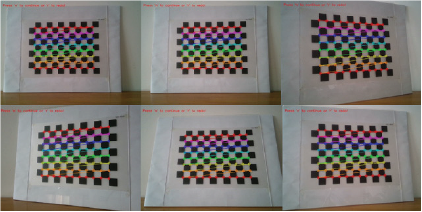
Figure 3: Corner detection diagram during camera calibration
After calibrating the RGB-D sensor, we obtain the internal parameter values of the left and the right infrared cameras and the RGB camera (
According to the calibration results, we can see that there is no rotation transformation between the left and right infrared cameras, and the relative horizontal translation is about 5.5 cm. There is both rotation transformation and horizontal translation between RGB camera and left infrared camera.
2.2 Align RGB Map and Depth Map
In order to fuse the RGB map and the depth map, alignment operations are required. The process of the alignment is to convert the depth value in the depth map to the space point of the world coordinate system, and then project it to the RGB map. The schematic diagram of alignment operation is shown in Fig. 4. The depth map of the Realsense sensor is acquired through left and right infrared cameras and infrared laser projector. The internal parameter matrices of the left and right cameras are the same according to the calibration results. The acquired internal parameter matrix of the depth map is also the same as the internal parameter matrix of the left and right cameras, Kd = Kl = Kr.
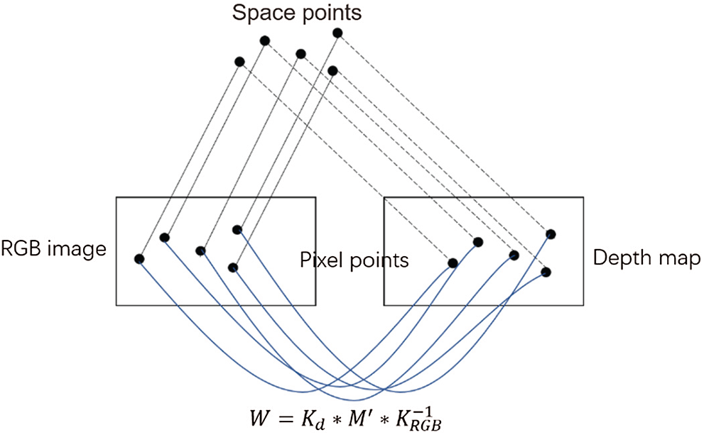
Figure 4: Schematic diagram of alignment operation
Assuming that the pixel coordinates of one point in the RGB map are represented as
Conversely, the conversion relationship between the pixel coordinate system of the RGB map and the depth map to the camera coordinate system are shown in formula (8) and (9):
The relationship between the depth map and the RGB map in camera coordinate system is expressed as formula (10). M′ is a
Substituting formulas (8) and (9) into (10), the following formula (11) can be obtained:
Let
W is a
Then formula (12) can be expressed as:
According to formula (14), the transformation relationship between depth map and RGB map can be calculated. The aligned RGB map and depth map in experiments are shown in Fig. 5.
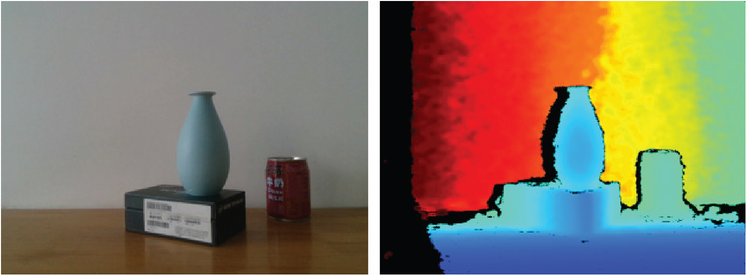
Figure 5: The aligned RGB map and depth map
ORB-SLAM2 is a visual SLAM method based on ORB feature and nonlinear optimization. It mainly includes camera tracking based on ORB feature, trajectory estimation, closed-loop detection and relocation, and local and global optimization [15]. It can only construct a sparse point cloud map of indoor scene by using the ORB feature. A direct method is proposed to replace the ORB feature method used in the parallel tracking thread. The surfel map is used to reconstruct the dense indoor scene. The improved ORB-SLAM2 flow diagram is shown as Fig. 6, the red line frame in the figure is the improved parts. The improved ORB-SLAM2 is mainly composed of four parallel threads and one global optimization thread. The four parallel threads are the trace thread, the local mapping thread, the loop closing detection thread, and the dense map builder thread.
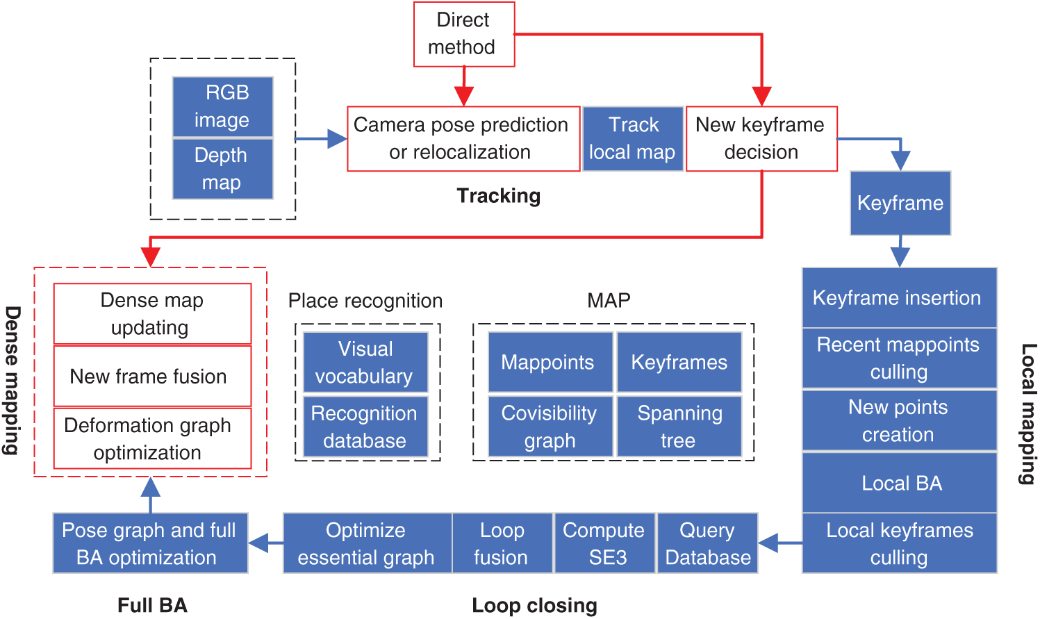
Figure 6: Improved ORB-SLAM2 flow diagram
2.4 Direct Method to Solve Camera Pose
In ORB-SLAM2, the camera pose is estimated by the ORB features which are extracted between two adjacent frames. The ORB feature is mainly composed of Oriented FAST and BRIEF. The extraction of Oriented FAST and the calculation of BRIEF are time-consuming. It is difficult to perform real-time processing operations on low-performance computers. In order to solve the time-consuming problem of ORB-SLAM2, this article proposes to use the direct method to solve the camera pose.
In the direct method, the camera pose is obtained by minimizing photometric error without concerning the feature between pixel points. The image points of a point
where Z1 is the depth of P in the camera coordinate system at the first moment, Z2 is the depth of P in the camera coordinate system at the second moment, K is the camera’s internal parameters, R and t are the rotation matrix and the translation matrix, respectively.
Comparing minimizing the reprojection error in the ORB feature method, the aim of direct method is to minimize photometric error, and the formula is
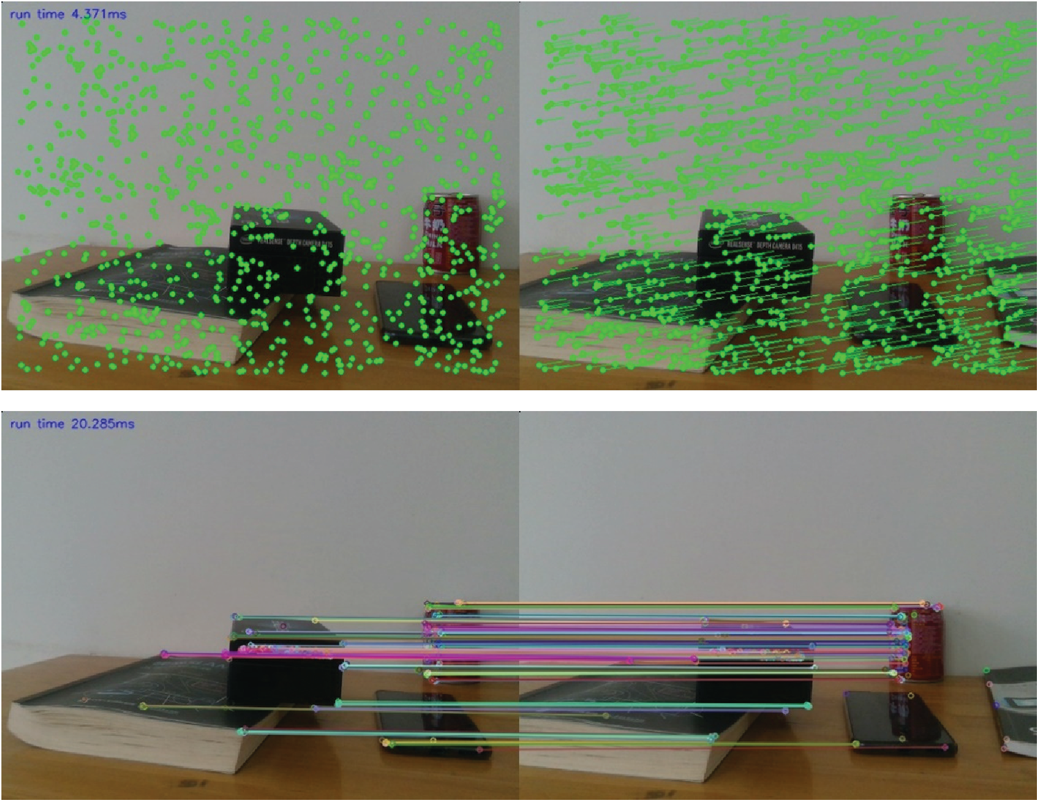
Figure 7: Comparison of results by ORB feature method (top) and direct method (bottom)
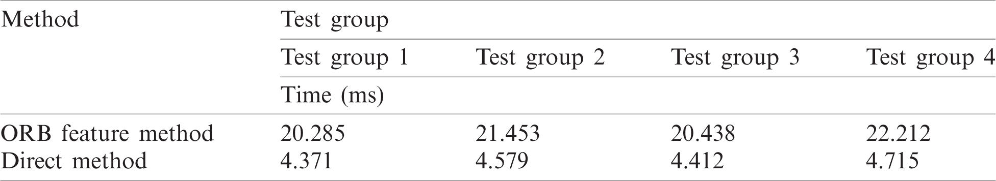
The direct method to solve the camera pose can be transformed into an optimization problem, which can be solved iteratively using the Gauss–Newton method. Fig. 7 shows the calculated results by the two methods. Tab. 1 shows the comparison of run-time by the two methods in several tests. The test results show that, compared with the ORB feature method, the solving speed is significantly improved by about 5 times.
Table 1: Comparison of the run-time by ORB feature method and direct method
2.5 Dense Reconstruction of Scenes
In this article, Surfel is used to fuse the depth map and RGB map obtained from RGB-D sensor to reconstruct the indoor scene. Each surfel stores the location of the corresponding spatial point, the radius, the normal vector, the color, and the time information [16]. The position, normal vector, and color will be updated according to the weighted fusion result, and the radius is obtained by the distance between the surface and the optical center of camera [8]. The radius of each surfel is initialized according to the following formula:
where, d is the depth value corresponding to the surfel, f is the focal length of the depth camera, and nz is the normal z component obtained by central difference estimation of the depth map. The surfel is updated and expanded by continuously fusing the depth map and RGB map, and a densely 3D model based on surfel is reconstructed finally. Fig. 8 shows the densely reconstructed three-dimensional model by Surfel.
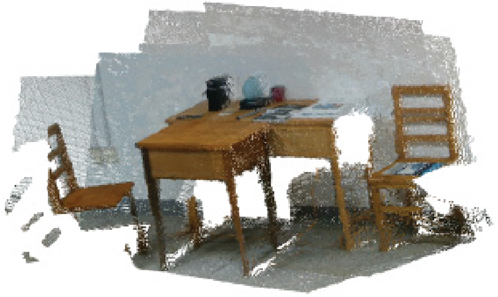
Figure 8: Three-dimensional model reconstructed by Surfel
In this experiment, a notebook computer with Intel Core i5-4210U CPU and 12G memory is used to carry out the 3D reconstruction of indoor scene. The Realsense D415 sensor is driven to obtain RGB image and depth image with the API interface provided by Realsense SDK 2.0, and the frame rate is 30 fps. The 3D reconstruction map of laboratory scene is reconstructed by the improved ORB-SLAM2 algorithm. The reconstruction process and result are shown in Fig. 9. Experimental results show that the improved ORB-SLAM2 algorithm has greatly improved the processing speed and the density of the reconstructed scene map.
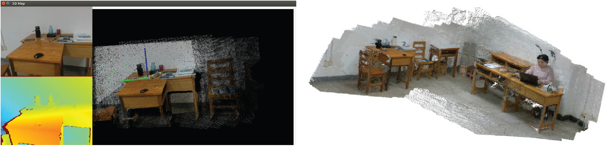
Figure 9: The diagram of 3D reconstruction process (left) and result of laboratory scene (right)
In order to solve the problem of time-consuming and sparse reconstruction by the ORB-SLAM2 scheme, the direct method based on light intensity is used to calculate the camera pose, and the surfel model is used for fusion. A dense scene reconstruction solution is proposed with the depth map and RGB map obtained from RGB-D sensor. Results show that the improved ORB-SLAM2 scene reconstruction method has a great improvement in processing speed and the density of the reconstructed scene map.
Acknowledgement: The authors would like to thank the anonymous reviewers and the editor for the very instructive suggestions that led to the much-improved quality of this paper.
Funding Statement: This work was supported by Henan Province Science and Technology Project under Grant No. 182102210065.
Conflicts of Interest: The authors declare that they have no conflicts of interest to report regarding the present study.
1. B. Yuan, “Research on key technologies of 3d reconstruction of indoor scene based on RGB-D sensor,” M.A. dissertation. Beijing University of Posts and Telecommunications, China, 2019. [Google Scholar]
2. Z. Du, Y. Ma, X. Li and H. Lu, “Fast scene reconstruction based on improved slam,” Computers, Materials & Continua, vol. 61, no. 1, pp. 243–254, 2019. [Google Scholar]
3. X. Zhang, P. Wang, W. Sun and N. I. Badler, “A novel twist deformation model of soft tissue in surgery simulation,” Computers Materials & Continua, vol. 55, no. 2, pp. 297–319, 2018. [Google Scholar]
4. W. Sun, M. Sun, X. Zhang and M. Li, “Moving vehicle detection and tracking based on optical flow method and immune particle filter under complex transportation environments,” Complexity, vol. 2020, no. 16, pp. 1–15, 2020. [Google Scholar]
5. J. Niu, Y. Jiang, Y. Fu, T. Zhang and N. Masini, “Image deblurring of video surveillance system in rainy environment,” Computers, Materials & Continua, vol. 65, no. 1, pp. 807–816, 2020. [Google Scholar]
6. R. A. Newcombe, S. Izadi, O. Hilliges, D. Molyneaux and D. Kim, “KinectFusion: Real-time dense surface mapping and tracking,” in Proc. ISMAR, Basel, Switzerland, pp. 127–136, 2011. [Google Scholar]
7. R. A. Newcombe, D. Fox and S. M. Seitz, “DynamicFusion: Reconstruction and tracking of non-rigid scenes in real time,” in Proc. IEEE CVPR, Boston, MA, USA, pp. 343–352, 2015. [Google Scholar]
8. T. Whelan, S. Leutenegger, R. F. Salas-Moreno, B. Glocker and A. J. Davison, “ElasticFusion: Dense SLAM without a pose graph,” in Proc. Robotics: Science and Systems. Rome, Italy, 2015. [Google Scholar]
9. M. Dou, S. Khamis, Y. Degtyarev, P. Davidson and S. P. Fanello, “Fusion4D: Real-time performance capture of challenging scenes,” ACM Transactions on Graphics, vol. 35, no. 4, pp. 1–13, 2016. [Google Scholar]
10. A. Dai, M. Niessner, M. Zollhoefer, S. Izadi and C. Theobalt, “BundleFusion: Real-time globally consistent 3D reconstruction using on-the-fly surface re-integration,” ACT Transactions on Graphics, vol. 36, no. 3, pp. 1, 2017. [Google Scholar]
11. W. Sun, X. Zhang and X. He, “Lightweight image classifier using dilated and depthwise separable convolutions,” Journal of Cloud Computing: Advances, Systems and Applications, vol. 9, no. 1, pp. 1–12, 2020. [Google Scholar]
12. F. Endres, J. Hess, J. Sturm, D. Cremers and W. Burgard, “3D mapping with an RGB-D camera,” IEEE Transactions on Robotics, vol. 30, no. 1, pp. 177–187, 2014. [Google Scholar]
13. R. Mur-Artal and J. D. Tardós, “ORB-SLAM2: An open-source slam system for monocular, stereo, and RGB-D cameras,” IEEE Transactions on Robotics, vol. 33, no. 5, pp. 1255–1262, 2017. [Google Scholar]
14. R. Mur-Artal, J. M. M. Montiel and J. D. Tardós, “ORB-SLAM: A versatile and accurate monocular SLAM system,” IEEE Transactions on Robotics, vol. 31, no. 5, pp. 147–1163, 2015. [Google Scholar]
15. K. Wei, “A study on real-time dense reconstruction algorithm based on RGB-D data,” M.A. dissertation. Huazhong University of Science and Technology, China, 2019. [Google Scholar]
16. K. Wang, F. Gao and S. Shen, “Real-time scalable dense surfel mapping,” in Proc. ICRA, Montreal, QC, Canada, pp. 6919–6925, 2019. [Google Scholar]
 | This work is licensed under a Creative Commons Attribution 4.0 International License, which permits unrestricted use, distribution, and reproduction in any medium, provided the original work is properly cited. |