DOI:10.32604/cmc.2021.017333
| Computers, Materials & Continua DOI:10.32604/cmc.2021.017333 | |
| Article |
Enhancements of SDR-Based FPGA System for V2X-VLC Communications
1Department of Cybernetics and Biomedical Engineering, Faculty of Electrical Engineering and Computer Science, VSB–Technical University of Ostrava, Ostrava-Poruba, 708 00, Czechia
2Department of Electronics, Faculty of Electrical Engineering and Computer Science, VSB–Technical University of Ostrava, Ostrava-Poruba, 708 00, Czechia
3Department of Computer Science, Faculty of Electrical Engineering and Computer Science, VSB–Technical University of Ostrava, Ostrava-Poruba, 708 00, Czechia
*Corresponding Author: Rene Jaros. Email: rene.jaros@vsb.cz
Received: 27 January 2021; Accepted: 19 March 2021
Abstract: This pilot study focuses on a real measurements and enhancements of a software defined radio-based system for vehicle-to everything visible light communication (SDR-V2X-VLC). The presented system is based on a novel adaptive optimization of the feed-forward software defined equalization (FFSDE) methods of the least mean squares (LMS), normalized LMS (NLMS) and QR decomposition-based recursive least squares (QR-RLS) algorithms. Individual parameters of adaptive equalizations are adjusted in real-time to reach the best possible results. Experiments were carried out on a conventional LED Octavia III taillight drafted directly from production line and universal software radio peripherals (USRP) from National Instruments. The transmitting/receiving elements used multistate quadrature amplitude modulation (M-QAM) implemented in LabVIEW programming environment. Experimental results were verified based on bit error ratio (BER), error vector magnitude (EVM) and modulation error ratio (MER). Experimental results of the pilot study unambiguously confirmed the effectiveness of the proposed solution (longer effective communication range, higher immunity to interference, deployment of higher state QAM modulation formats, higher transmission speeds etc.), as the adaptive equalization significantly improved BER, MER and EVM parameters. The best results were achieved using the QR-RLS algorithm. The results measured on deployed QR-RLS algorithm had significantly better Eb/N0 (improved by approx. 20 dB) and BER values (difference by up to two orders of magnitude).
Keywords: 5G; feed-forward software defined equalization; multistate quadrature amplitude modulation; software defined radio; visible light communication
Vehicular lights have been slowly shifting towards full LED lamps for some time. Old halogen and Xenon HID bulbs are abandoned in favor of full LED matrixes. LED itself offers multiple advantages, such as low consumption, longevity, resistance to humidity and fast switching capabilities, which can be leveraged for visible light communication (VLC) [1]. In recent years, VLC surfaced as an alternative to conventional radio frequency (RF) technology, since the current communication bands often lack free channels, which is notable particularly in Wi-Fi or in industrial, scientific and medical bands [2,3].
VLC is an optical wireless technology which operates from 380 to 780 nm, using a visible light source as a signal transmitter, free space environment as transmission medium and the appropriate PIN photodetectors, pricier avalanche photo diodes (APDs) [4], advanced CMOS cameras [5–7], or inexpensive solar panels as receivers.
VLC seems to be capable technology for short-range, or possibly in the future even long-range data transmissions, and accurate positioning in congested environments. Appliances vary greatly-spanning from conventional everyday lighting to vehicular solutions, deployment in hospitals (as it does not interfere with sensitive equipment) or simply as an alternative to typical local area networks (LAN). Rapid expansion of LED is crucial for this technology, as it offers multiple advantages such as long lifespan, low power consumption, high tolerance to humidity, high efficiency, and fast switching. However, the main advantage of VLC based on LED is the use of the visible spectrum (380–780 nm). LED can therefore perform communication functionality while maintaining the original function as illumination lighting, thus further reducing power consumption and emissions. This technology can work in a standalone mode or even as a supplementary technology to already deployed solutions, such as mobile networks. It is currently often explored as a last mile technology for some 5G scenarios [8–10] and some teams even presented their own 5G/VLC hybrid architecture, such as Feng et al. [11] and their 5G network with indoor VLC sub technology. Electric vehicles are also selling quite well, and it is estimated that by 2030, there will be approximately 250 million electric vehicles on roads around the world [12]. These vehicles are manufactured exclusively with LED lamps.
Apart from previously mentioned hybrid 5G-VLC technologies, the fifth generation of broadband cellular network itself was designed for cellular V2X deployment. Although the 4G is a capable technology supporting V2X, IoT and other low-power sensor communication technologies, the 5G is pushing boundaries to another level. The next evolution of vehicles is pushing towards autonomous vehicles and advanced safety protocols. These technologies require a complex vehicle maneuvering, which are dependent on two-way rapid communications and driving intentions sharing. 4G based C-V2X technologies offered partial solutions, as the speed and mainly latency was limited. The 5G offers higher transmit speeds, unparalleled latency, since it operates in three separate bands and more energy efficient solution. 5G network is also highly scalable and flexible, which is needed to adapt to target use cases and spectrum. Starting from C-V2X release 15 and beyond, the 5G NR was fully incorporated into this 3GPP standardization [13]. However, the ongoing evolution still maintain the backward compatibility to the previous releases of the same technological generation. Families tend to buy a new vehicle to last at least 5 to 10 years. Therefore, its necessary to maintain ongoing compatibility to ensure the new safety protocols from newer vehicles work with older technological revisions. For example, the interworking is designed for direct V2V communication and guarantees that Release 15/16 compatible vehicle is capable of communication directly with Release 14 compatible vehicle via Release 14 services. Since the C-V2X 5G is backwards compatible with LTE technologies, it means that the 5G network and an LTE device can communicate via direct V2V. However, it important to mention that Release 14 devices are mainly designed for safety protocols while the more advanced Release 15+5G New Radio (NR) based devices can offer more advanced technologies. It is expected that the previously deployed Release 14 LTE-V2X vehicles will be compatible with later 5G User Equipment (UEs) that support V2X services via dual-mode LTE and 5G hybrid. The 5G is currently deployed worldwide and 5G capable vehicles should arrive soon on the market. 3GPP C-V2X Release 17 is currently deployed in Stages-the Stage 2 should arrive in Q2/Q3 of 2021 while Stage 3 and Protocol coding deadlines are scheduled for 2022. Both 5G and LTE are still developed in Releases 16 and 17 [14], however LTE activities are somewhat limited due to the growing maturity of the LTE radio-access technology. While the cellular V2X systems offer a plethora of new technologies a hybrid approach outlined by this article can fill in the gaps of these technologies. Communication in certain scenarios, for example in tunnels or during vehicular platooning, can be much more efficient via alternative technologies, such as VLC.
The VLC-based technologies offer a variety of future applications, spanning from localization and data transmissions in factories to short-range communication between vehicles or even deployment in hospitals and other institutions. Fig. 1 describes a concept of smart city connected to various VLC technologies [15]. These technologies offer an alternative to C-V2X or DSRC [16] based solutions, which could be integrated into vehicles or public lighting, improving everyday life. Since the C-V2X operates on a somewhat similar concept, a limited or even full compatibility could be implemented as well. Smart traffic lights, offering fresh traffic information, smart vehicle charging stations, preemptive collision avoidance systems or indoor VLC-based localization [17] are technologies which could complement already deployed C-V2X solutions. Vehicle-to-vehicle, vehicle-to-home, vehicle-to-grid, vehicle-to-device and vehicle-to-infrastructure scenarios are all possible, as the VLC standardization offers a different device classes, covering various light source intensities or even battery backhauls.
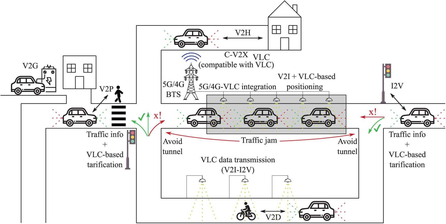
Figure 1: Smart city concept with various VLC-based technologies
Joshi et al. [18] in 2019 presented their own approach on feasibility of VLC-based V2X communications under various Environmental Deterrents. Based on their research, different deterrents have various degree of influence on the VLC testbed. Their approach is somewhat similar to our work presented in MDPI Electronics earlier in 2019 [19]. Based on our combined results dense smoke or fog has significant effect on VLC communication. This manuscript will expand on problematics, presenting at least partial solution-deployment of adaptive equalization algorithms.
Visible Light Communication appears as an available communication technology, which would work well in congested or hazardous environments. Since it does not interfere with other RF wireless technologies, it can be freely used in addition to them. Despite the obvious limitations in the somewhat short range and line-of-sight requirements, the vehicle can communicate with its neighbors and close infrastructure, which would be especially useful for sending warning messages. As stated by Cui et al. [20], VLC can even achieve better results than DSRC in highly congested environments since it’s not influenced by Doppler shift.
The team at Technical University of Ostrava has extensive experience with signal processing, which will be a basis for further research in VLC. The collective wants to continue with real-world experiments and implementations in vehicles stationed at laboratories. Some experiments proved, that results from simulated environments can’t be reached in real-world scenarios. Therefore, any further research must be backed by relevant measured data and tested on hardware platform resembling the future deployment scenarios [19,21].
Following text describes our work, which focuses on QAM-based testing platform. QAM was used since it is basically a foundation stone for several modern digital modulations, including OFDM. A whole platform will be presented, with detailed description of hardware components and testing methodic. The whole experimental phase will focus on influence of adaptive equalization on measured parameters during various atmospheric phenomena. As the platform is significantly limited by dimensions of inhouse designed testing box (5.5 m), even the higher state QAM modulations were tested. A development of our own OFDM-based system, which will leverage knowledge gained from experiments presented in this manuscript is currently underway and will be a topic of future publications.
The presented system is based on adaptive optimization of the feed-forward software defined equalization (FFSDE). Three different adaptive methods were used for testing. The least mean squares algorithm (LMS) [22], normalized LMS algorithm (NLMS) [23], and QR decomposition-based recursive least squares (QR-RLS) [24] algorithm. All these methods provided good accuracy in different areas and have a potential to improve the system performance [21,25].
Adaptive algorithms are used mainly in an unknown environment, as they can adapt their coefficients based on varying circumstances. These methods are based on calculation of error signal
Least mean squares algorithm belongs into stochastic gradient descent adaptive methods based on Wiener filtering theory, stochastic averaging, and the least squares method. Stochastic gradient descent adaptive algorithms are the most used iterative algorithms for optimizing differentiable objective functions. Every iteration of LMS algorithm requires calculation of adaptive filter output signal
2.2 Normalized Least Mean Squares
Normalized LMS algorithm uses a variable step size
The same iterative procedure is performed as in LMS algorithm. Every iteration of NLMS algorithm requires calculation of adaptive filter output signal
where:
2.3 QR Decomposition Based Recursive Least Squares
Recursive least squares algorithm has its own statistic conception and is based on recursive determination of weight coefficients, theory of Kalman filtration, time averaging, and the least squares algorithm. The advantage of RLS algorithm is that it uses the values of previous error
Modification of RLS algorithm called QR-RLS uses triangulation process and exhibits good mathematical properties. This algorithm is numerically stable and provides positive definiteness. As in case of other described adaptive algorithms, QR-RLS algorithm works in a few iterative steps. Every iteration of QR-RLS algorithm requires calculation of adaptive filter
2.4 Optimization of LMS and RLS Algorithms
This work is built upon foundations from earlier experiments with adaptive equalization techniques. Feed-Forward Software Defined Equalization (FFSDE) is a strong tool, which can significantly improve properties of VLC or RF channels. The parameters themselves were estimated based on a stochastic gradient adaptation approach and real-world experiments presented in this work should back up these earlier findings. Presented measurements fully correlate with our earlier experiments, which were carried out in a simulated transmission channel.
Continuous adaptive optimization of LMS and RLS algorithms for equalization must be performed to achieve the best results. The presented system is implemented on SDR, leveraging the raw performance of FPGA. Parameters of individual algorithms are periodically updated. To our best knowledge, similar system was never before tested on a functional, non-simulated VLC link. NLMS and QR-RLS algorithms were also used, but since they share equations with basic LMS and RLS algorithms, their explanation is not necessary.
For LMS algorithm (as well as for the NLMS algorithm), two parameters—filter order N and step size
In case of QR-RLS algorithm, two parameters-filter order N and forgetting factor
Fig. 2 shows block diagram of LMS, NLMS or QR-RLS algorithm optimization. First, the input of the receiver (training data) are distorted by transmitting channel. Then the received data are equalized using the known training data with either Nk0 and
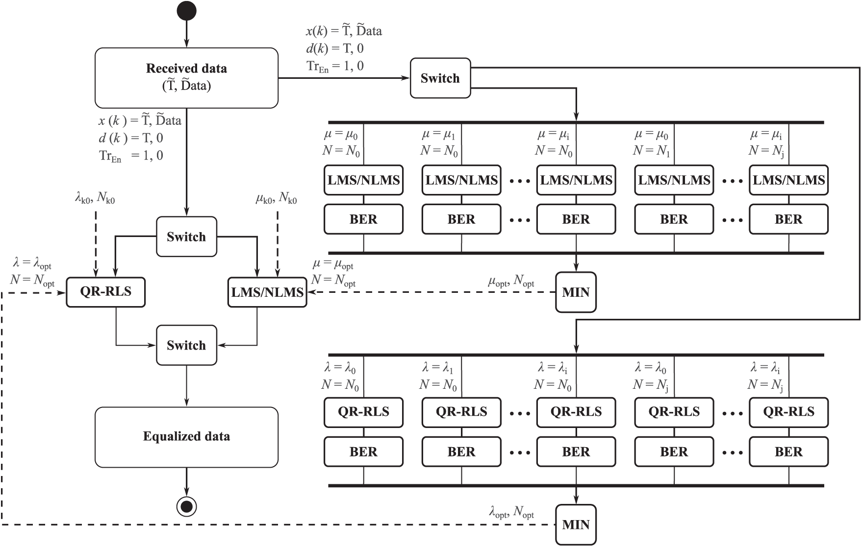
Figure 2: Block diagram of LMS, NLMS or QR-RLS algorithm optimization
The whole measuring platform is built as a virtual instrument-relying heavily on LabVIEW programming environment and software defined radios. As the scenarios with indoor light source were already tested out earlier, an “outdoor” variant was chosen for tests with adaptive equalization. An Octavia III taillight was chosen as a transmitting element, whereas a Thorlabs PDA36A-EC [28] photodetector was used as a receiving element. Bias-Tee XZ85-12G-S+ was used to modulate the transmitting light source. An amplifier operating at 1 to 500 MHz was also incorporated on transmitting side. Two NI USRP 2921 [29] software defined radios were used, one for each transmitting/receiving element-these radios used a set of Ettus LFTX/LFRX daughterboards instead of the original ones. A high-end PC running LabVIEW was used for generation and evaluation of transmitted data. The block diagram of the whole setup can be seen in Fig. 3.
A robust software side was developed in LabVIEW programming environment and can be divided into multiple blocks. Various parameters, such as MER, BER, SNR or RSL can be displayed. The software can also display constellation and eye diagrams.
The following configuration was used during experiments: 3 MHz carrier frequency with variable bandwidth from 1 MHz up to 4 MHz with step size of 1 MHz. Three adaptive algorithms were tested-LMS, NLMS and QR-RLS.
Fig. 4 shows experimental results of LMS algorithm simulations. This figure describes a relationship between BER values and

Figure 3: Block diagram of the whole platform with various scenarios

Figure 4: Simulation of LMS algorithm parameters with ideal N and
A special plastic box constructed at Technical University of Ostrava, was inserted between transmitting and receiving elements. This box can be used to simulate various natural phenomena, which can be encountered on roads. Four scenarios were tested and measured-thermal turbulence, two rain intensities and fog. The box dimensions as well as additional equipment can be seen in Fig. 5. For further information regarding to the box, please refer to our earlier publications [19,21].

Figure 5: Diagram and dimensions of the box in which the measurements took place
A first set of measurements was carried out in the empty box and was used as a reference. A frequency attenuation characteristic was measured to determine the ideal carrier frequency.
Fig. 6 shows various photographs taken during measurements. Figs. 6a and 6b were taken during rain simulations, Figs. 6c and 6d were taken during thermal turbulence scenario, and Figs. 6e and 6f were taken during measurements with fog.
3.1 Influence of Thermal Turbulence on VLC
A set of three electric air heaters located below the box at predefined distances was used to simulate thermal turbulence. These heaters were mounted on the bottom of the box, and vents on the top were opened to ensure proper circulation of air. In addition, windows in the laboratory were opened. The temperature in the box varied, ranging between 40 and 50

Figure 6: Photographs taken during measurements. (a) Measurements during “rain” scenario; (b) Octavia III tail light; (c), (d) Measurements during “fog” scenario; (e), (f) Measurements with direct visibility-the analysis of attenuation characteristics
For example, in case of the Eb/N0 for 8-QAM, it is noticeable that QR-RLS improves this parameter by approx. 9 dB (in comparison to the reference values), while the LMS and NLMS algorithms shows improvement of approx. 2 to 3 dB. The difference between non-equalized state and equalized signal is in tenths of a percent. However, this changes with higher modulation states. In case of 1024-QAM the QR-RLS shows up to 14 dB improvement of Eb/N0, while NLMS and LMS offers up to 3 to 4 dB.

Figure 7: Dependence of Eb/N0 on the used modulation format, 1 MHz bandwidth, comparison of the effect of temperature turbulence
Overall, the temperature turbulence has negligible effect on the measured parameters. These parameters deteriorate only during measurements with higher state modulations (the reduction of the signal-to-noise ratio has a significantly greater effect on higher modulations formats). QR-RLS seems to be the best adaptive algorithm for this measurement, as even at 1024-QAM, the bit error rate never exceeds 10−4, while the other algorithms are approximately two orders of magnitude higher.
3.2 Influence of Rain on Visible Light Communication
Measurement of the influence of rain on communication based on VLC technology was carried out in the “modified” box environment. A 2.5 m long rain simulation construction was inserted into the box. Two flow rates (42 and 22 l/min) were picked for measurements-simulating rain of various intensity. During the measurement, a partition was inserted in the middle of the box, as the water must circulate through the pump. A comparison of the individual attenuation characteristics can be seen in Fig. 8. This figure also mentions the specific scenario, where the partition was removed. When the central partition is removed, the attenuation is reduced (by approximately 3 dB). There is also a case where the attenuation frequency characteristic was measured without rain and without a central partition, but with the wet face of the box. The attenuation in this case is approximately 4–5 dB higher than normal. In this case, the attenuation is obviously lower than in the case of rain. This condition (wet surface) can often occur in real-world scenarios. By comparing the attenuation frequency characteristic of normal state with rain in combination with center partition, it can be noticed that the difference in attenuation is about 15 dB at a flow rate of 42 l/min and about 12 dB at a flow rate of 22 l/min.
Figs. 9 and 10 cover the comparison of the individual parameters, for various multistate modulation formats and 1 MHz bandwidth.

Figure 8: Attenuation frequency characteristic of the rain simulation with a flow rate of 42 l/min

Figure 9: Dependence of BER on the used modulation format, 1 MHz bandwidth

Figure 10: Dependence of E
By comparing the effect of rain intensity, it can be found out that the higher flow rates influence the measurements significantly more, as was expected. When comparing 256-QAM values from both scenarios, it can be noticed that the BER of QR-RLS algorithm is in the order of 10−5 for both flow rates. In comparison LMS reached only 10−3 for lower flow rate, whereas for higher flow rate, the values reached even 10−1. In comparison, NLMS reached approx. 10−2 for both flow rates. When the adaptive equalization is deactivated, BER values reached 10−1 for lower flow rate and 1 for higher flow rate.
As far as Eb/N0 is concerned, QR-RLS also works best, as it improves this parameter by 20 dB (compared to the non-equalized state) for a flow rate of 22 l/min. At a flow rate of 42 l/min, the Eb/N0 value was measured at 38 dB (in comparison to flow rate of 22 l/min with 40 dB). LMS and NLMS both provided significantly worse results than QR-RLS but still outshined non-equalized state.
Overall, all three algorithms managed to significantly improve performance of the whole system. QR-RLS provided the best results, slowing the deterioration of measured parameters at higher state modulation formats and providing higher reachable maximal speeds, thus possibly offering longer communication distances.
3.3 Influence of Fog on Visible Light Communication
The third scenario was also carried out in the box, this time with attached fog machine. The holes in the box were sealed at the beginning of the measurement to prevent fog from escaping into the environment. Gradually, some holes were opened to support the complete dissolve of the fog. Antari Alpha F-80Z was used to generate fog.
As the fog had no constant concentration during the whole measurement and changed constantly, a way of monitoring of its density was introduced. A reference laser-photodetector combination with known power was added to the box to measure fog density. By using this laser and photodetector, the various power levels were measured as a function of time. This way it could be at least estimated how dense the fog was. This measurement can be seen in Fig. 11.
Power spikes and dips are caused by fog mixing with air during the opening of previously mentioned holes. Constellation diagrams of some modulations with adaptive algorithms can be also seen in this Fig. 11. The fog concentration was constantly changing; therefore, some measured values are written next to the constellation diagrams.

Figure 11: Attenuation frequency characteristics of the fog simulation. The higher the power level of the reference laser, the lower the fog concentration
QR-RLS adaptive algorithm was the first to successfully achieve a reliable connection. Therefore, it has the best measured values. NLMS and LMS both had a very similar results and followed shortly after QR-RLS. The non-equalized system was the worst and last one to establish a connection. Measurements were significantly time consuming and it was not possible to measure all modulation formats for individual bandwidths and individual adaptive algorithms immediately after the successful communication was established.
Melles Griot 25-LHP-151-230 laser in combination with Thorlabs S120C were used for reference measurements. The power level measurements were carried out by Thorlabs PM100USB power meter. A frequency attenuation characteristic was measured as well and can be seen in Fig. 12. The higher concentration of fog has a significant impact on received power levels, thus increasing noise as well.

Figure 12: Attenuation frequency characteristics of various reference laser power levels after passing through a fog filled box
After the box was completely filled with fog, the communication completely ceased to work. Only after the fog dissipated a bit, the communication was successfully established on 4-QAM modulation. During the dissipation which followed, other higher state modulation formats gradually “opened.” However, 2048-QAM could be only used in completely empty box. Fig. 12 shows the gradually increasing power levels of reference laser (thus indicating lower fog density) with highlighted points in which the communication established on certain modulation formats. All four scenarios (QR-RLS, LMS, NLMS, without EQ) are visible for 4-QAM modulation format. It is noticeable that QR-RLS provides the best results overall, reaching higher states first. Further results are listed in Tabs. 1–3.
As mentioned before, the presented platform is a logical step forward from our earlier work. The atmospheric phenomena are a significant issue for future deployment of various VLC-based systems, mainly in the transport industry. As presented, the adaptive software equalization is an advantageous addition to any system which might show some of the untapped potential of hardware itself. Since the implementation was completely software-based, the presented VLC platform reached up to 30% to 40% better results across the whole board, without any additional hardware modifications.
The system reached satisfactory results, which were based on preliminary simulations on NI Vector Signal Transceivers (VST). Apart from the thermal turbulence scenario, which had negligible effect on the communication parameters, each other natural phenomena significantly influenced the monitored parameters. While the QR-RLS offered the best parameters across the board, it also has the highest computational requirements. This fact can be mitigated by FPGA implementation, which offers significantly higher performance than simulation of the whole system on high end PC. LMS and NLMS have somewhat lower performance but can be more efficient, depending on the final deployment.
Table 1: Table of reference laser power levels in fog filled box (levels were written down when specific modulation formats opened), including parameter settings for LMS algorithm

The main advantage of the whole system is its modularity and fast adaptability. During the development, our team encountered a number of problems which required multiple approaches. Thanks to the LabVIEW and NI hardware, we were able to test each scenario individually and in quick succession. Each “branch” of research was therefore pinpointed in earlier stages and implemented/tested very fast. Despite the major advantages, the platform has one significant disadvantage—it heavily relies on the NI hardware components. The final product for deployment has to be ported to more user-friendly product. To mitigate these problems a periodically produced “beta” versions are planned. While the main platform will stay on the modular NI system, the long-term testing branches will be ported on suitable hardware components. It would be therefore possible to estimate important parameters on real components, while also considering the estimated price of whole platform.
Table 2: Table of reference laser power levels in fog filled box (levels were written down when specific modulation formats opened), including parameter settings for NLMS algorithm

Advanced signal processing methods are the basis of presented experiments. For these experiments, three algorithms were chosen QR-RLS, LMS and NLMS. While the presented data clearly speaks in favor of these solutions, there are other approaches that should be considered, mainly modern neural networks. The presented system should in the future work as a completely cognitive radio, so it could choose the most suitable solution for the used hardware and conditions.
As part of a future real-world application, a series of experimental measurements and analyses were performed on an experimental model of Skoda Superb III. generation (Fig. 13). Two vehicles, ExpVeh #1 and ExpVeh #2, have been specially modified for research purposes. Operating signals, resp. longitudinal and lateral control data as well as on-board system data (BCM, Instrument Cluster, ABT) are transmitted on both sides through a development communication interface that has been integrated into both vehicles. Through the interface it is possible to access all data transmitted on the communication buses, except for specific data that are only available on the private buses (Fig. 14). These consist of several thousand data signals; a specified set was handpicked for tests, based on different QoS [30]. The control buttons, Instrument Cluster display, resp. indicator lamps and central external display (ABT) form a human machine interface (HMI) [31], which is important both for entering requests and monitoring selected transmitted information within V2X communication (C2C in the presented scenario), respectively. serves to alert the driver within the functionality of the test scenario described below.
Table 3: Table of reference laser power levels in fog filled box (levels were written down when specific modulation formats opened), including parameter settings for QR-RLS algorithm


Figure 13: Two experimental Skoda Superb III vehicles. (a) Liftback experimental vehicle A; (b) Estate experimental vehicle B
During the driving tests, the transmission of information about obstacles on the road was tested within the investigated C2C communication (SDR-C2C-VLC). Specifically, for two moving vehicles driving at a visible distance in a row. The first vehicle identifies obstacles through factory sensor systems (radar and camera). These are pedestrians, wild animals and other vehicles that unpredictably disturb the space in a straight line. Object information is transmitted as a request to the second vehicle following the first vehicle. These requirements have a defined seriousness and their global meaning “unpredictable obstacle.” This call causes an acoustic and visual alert to the driver of the other vehicle of a critical road situation. Since these vehicles are also connected to campus mobile network (currently a hybrid of 4G and 5G), the V2X-VLC-5G/4G hybrid technology could be also tested in the future. The testing vehicles are already capable of 4G V2X communication and the addition of VLC could be used to in-depth testing of the whole concept.

Figure 14: Extraction of sensor data from CAN bus and consecutive Ethernet conversion for SDR-V2X-VLC system
A brand-new platform for testing of new technologies (CPIT TL3) is currently being finalized in Technical University of Ostrava. The whole building will be split into blocks, covering various fields of research, spanning from smart factory or home care to automotive [32,33]. Laboratory dedicated for development of VLC technologies and their integration into everyday life will be also part of CPIT TL3. It will be built on National Instrument hardware, latest NI PCI eXtensions for Instrumentation (PXI) and high-end computer. The laboratory will be also partially integrated into all three main parts of CPIT TL3. The developed technology can be therefore integrated not only in vehicles but also in manufacturing lines, smart homes or possibly even into medical equipment. Further details are provided in PR article [34].

Figure 15: Comparison of non-equalized constellations (a), (d), (g), and (j) vs. NLMS equalized constellations (b), (e), (h), and (k) and QR-RLS equalized constellations (c), (f), (i), and (l) for 4, 16, 64, 512-QAM modulation formats. Empty box, 1 MHz bandwidth
Equalization is not always advantageous. During certain situations—when the signal has close to ideal parameters—equalization algorithms can have a negative impact on received constellations. Fig. 15 shows this situation. Figs. 15a, 15d, 15g, and 15j represent the non-equalized scenario, whereas the Figs. 15b, 15e, 15h, and 15k show the NLMS equalized constellations and Figs. 15c, 15f, 15i, and 15l stands for QR-RLS. Measurements were carried out in an empty box with 1 MHz bandwidth and 3 MHz carrier frequency. The NLMS constellation points tend to deviate from their ideal positions significantly more in comparison to non-equalized data. In comparison, the QR-RLS clearly improves the received data. Therefore, for the final deployment, an adaptive technique, which would compare parameters and turn off/switch equalizer if needed, is a must. However, this limitation can be also overcome by advanced equalization methods, as indicated by QR-RLS.
Technical University of Ostrava has a custom and newly developed testing polygon for SMART technologies called BROADBAND

Figure 16: Comparison of non-equalized and QR-RLS equalized data. (a) and (b) were taken in rain scenario with full flow rate during 32-QAM modulation format measurements. (c) and (d) stand for 128-QAM rain scenario with half flow rate. (e) and (f) were taken in fog scenario with 1024-QAM modulation format. All measurements were carried out for 3 MHz carrier frequency and 4 MHz bandwidth
This paper presents results of our ongoing research focused on VLC. The presented work deals with various aspects of FFSDE and clearly shows the positive impact of its implementation. The system itself is built as a virtual machine—leveraging advantages of virtual instrumentation, thus ensuring fast adaptivity and high degree of modularity. Throughout the experiment, various shortcomings were localized and a potential candidate for new and more suitable parts were already identified, leading to even better results.
The used algorithms reached different results, depending heavily on the tested scenarios. Starting with thermal turbulence, it was clearly noticeable that it has negligible effect on the measured parameters. In the worst-case scenario, the LMS and NLMS managed to improve the Eb/N0 parameter by approx. 3 to 4 dB, while the QR-RLS reached 9 dB. The situation is vastly different in case of rain scenarios. QR-RLS managed to improve Eb/N0 by 20 dB (in case of 22 l/min) and 22 dB (in case of 42 l/min). The most significant impact was measured during fog scenarios. Since it was hard to maintain a reliable connection a different approach was chosen. The QR-RLS again showed the best results across the board and completely outshined both the LMS and NLMS. In the most important scenarios, the QR-RLS outperformed both LMS and NLMS by more than 50%. Overall, the adaptive software equalization proved to be an important addition to any system, which can show the untapped potential of the used hardware.
Based on the previous paragraph, it is clearly visible that the QR-RLS is the most suitable technique for future implementation. However, as was mentioned in the discussion, the presented platform, in its current state, is not suitable for long-term deployment into vehicles. There has to be a branch with miniaturized one-purpose hardware. The current implementation is modular, which is both an advantage (for development) and disadvantage (for real deployment). The fast switching can also influence the lifespan of LEDs in vehicular light sources. Further testing of this problematics is needed, since it would influence maintenance cost. These problems will be solved in future research and publications focusing on each of these topics.
The whole experiment was carried out on the conventional Skoda Octavia III taillight. The transmitting light was not modified thus ensuring the results can be somewhat transferred and implemented in real vehicles. Various testing vehicles are already present in laboratories at Technical University of Ostrava and future experiments might be carried out on them as well.
The presented experiments clearly show that software defined equalization can offer a significant uplift in quality of transmitted signal, see Fig. 16. The results are mainly visible in scenario with fog and rain, where the deployment of QR-RLS maintained successful communication in much denser fog/rain in comparison to other algorithms or even completely bare system. The positive impact of equalization was also showed in measurements with rain, where the adaptive equalization offered significant uplift in measured parameters and thus also signal quality and stability.
The transmission to OFDM based system is currently planned and implementation of advanced software equalization techniques is a topic of further research, which will be built upon foundations laid by this article, as a number of foreign teams are focusing on their own OFDM platforms [35–40] or even MIMO solutions [41,42]. The 5G-VLC compatibility is the way and the presented platform will continue to evolve past current limitations.
Acknowledgement: This work was supported by the European Regional Development Fund in the Research Centre of Advanced Mechatronic Systems project, Project Number CZ.02.1.01/0.0/0.0/16_019/0000867 within the Operational Programme Research, Development and Education, and in part by the Ministry of Education of the Czech Republic under Project SP2021/32.
Funding Statement: This research was funded by the European Regional Development Fund in the Research Centre of Advanced Mechatronic Systems project, Project Number CZ.02.1.01/0.0/0.0/16_019/0000867 and by 543 the Ministry of Education of the Czech Republic, Project No. SP2021/32.
Conflicts of Interest: The authors declare that they have no conflicts of interest to report regarding the present study.
1. R. M. Mare, C. Luiz Marte and C. E. Cugnasca, “Visible light communication applied to intelligent transport systems: An overview,” IEEE Latin America Transactions, vol. 14, no. 7, pp. 3199–3207, 2016. [Google Scholar]
2. S. Chen, J. Hu, Y. Shi, Y. Peng, J. Fang et al., “Vehicle-to-everything (V2X) services supported by LTE-based systems and 5G,” IEEE Communications Standards Magazine, vol. 1, no. 2, pp. 70–76, 2017. [Google Scholar]
3. A. W. Thompson and Y. Perez, “Vehicle-to-everything (V2X) energy services, value streams, and regulatory policy implications,” Energy Policy, vol. 137, no. 2, pp. 1–12, 2020. [Google Scholar]
4. Y. Li, M. Safari, R. Henderson and H. Haas, “Optical OFDM with single-photon avalanche diode,” IEEE Photonics Technology Letters, vol. 27, no. 9, pp. 943–946, 2015. [Google Scholar]
5. Z. Ong and W.-Y. Chung, “Long range VLC temperature monitoring system using CMOS of mobile device camera,” IEEE Sensors Journal, vol. 16, no. 6, pp. 1508–1509, 2016. [Google Scholar]
6. K. Liang, C.-W. Chow, Y. Liu and C.-H. Yeh, “Thresholding schemes for visible light communications with CMOS camera using entropy-based algorithms,” Optics Express, vol. 24, no. 22, pp. 25641–25646, 2016. [Google Scholar]
7. Y. Goto, I. Takai, T. Yamazato, H. Okada, T. Fujii et al., “A new automotive VLC system using optical communication image sensor,” IEEE Photonics Journal, vol. 8, no. 3, pp. 1–17, 2016. [Google Scholar]
8. R. Molina-Masegosa and J. Gozalvez, “LTE-V for sidelink 5G V2X vehicular communications: A new 5G technology for short-range vehicle-to-everything communications,” IEEE Vehicular Technology Magazine, vol. 12, no. 4, pp. 30–39, 2017. [Google Scholar]
9. B. Di, L. Song, Y. Li and Z. Han, “V2X meets NOMA: Non-orthogonal multiple access for 5G-enabled vehicular networks,” IEEE Wireless Communications, vol. 24, no. 6, pp. 14–21, 2017. [Google Scholar]
10. G. Naik, B. Choudhury and J.-M. Park, “IEEE 802.11 bd & 5G NR V2X: Evolution of radio access technologies for V2X communications,” IEEE Access, vol. 7, pp. 70169–70184, 2019. [Google Scholar]
11. L. Feng, R. Q. Hu, J. Wang, P. Xu and Y. Qian, “Applying VLC in 5G networks: Architectures and key technologies,” IEEE Network, vol. 30, no. 6, pp. 77–83, 2016. [Google Scholar]
12. Global EV Outlook 2019. Paris, France: International Energy Agency, 2019. [Online]. Available: https://www.iea.org/reports/global-ev-outlook-2019?fbclid=IwAR158aVbtE3yyoUJrd3_irOJbMcD3A4T6pYaGHTPSoWnrq-aq2d3tQ_9pCk. [Google Scholar]
13. Cellular V2X Communications Towards 5G. Bellevue, Washington, United States: 5G Americas, 2018. [Online]. Available: https://www.5gamericas.org/cellular-v2x-communications-towards-5g/. [Google Scholar]
14. 3GPP Releases 16, 17 & Beyond. Bellevue, Washington, United States: 5G Americas, 2021. [Online]. Available: https://www.5gamericas.org/3gpp-releases-16-17-beyond/. [Google Scholar]
15. S. Vappangi and V. M. Vakamulla, “Synchronization in visible light communication for smart cities,” IEEE Sensors Journal, vol. 18, no. 5, pp. 1877–1886, 2018. [Google Scholar]
16. R. Sayer, The Cost in Fatalities, Injuries and Crashes Associated with Waiting to Deploy Vehicle-to-Vehicle Communication. Ann Arbor: Transportation Research Institute, University of Michigan, pp. 1–10, 2018. [Google Scholar]
17. K. Qiu, F. Zhang and M. Liu, “Let the light guide us: VLC-based localization,” IEEE Robotics & Automation Magazine, vol. 23, no. 4, pp. 174–183, 2016. [Google Scholar]
18. K. Joshi, N. Roy, G. Singh, V. A. Bohara and A. Srivastava, “Experimental observations on the feasibility of VLC-based V2X communications under various environmental deterrents,” in IEEE Int. Conf. on Advanced Networks and Telecommunications Systems, Goa, India, pp. 1–4, 2019. [Google Scholar]
19. R. Martinek, L. Danys and R. Jaros, “Visible light communication system based on software defined radio: Performance study of intelligent transportation and indoor applications,” Electronics, vol. 8, no. 4, pp. 1–36, 2019. [Google Scholar]
20. Z. Cui, C. Wang and H.-M. Tsai, “Characterizing channel fading in vehicular visible light communications with video data,” in IEEE Vehicular Networking Conf., Paderborn, Germany, pp. 226–229, 2014. [Google Scholar]
21. R. Martinek, L. Danys and R. Jaros, “Adaptive software defined equalization techniques for indoor visible light communication,” Sensors, vol. 20, no. 6, pp. 1–23, 2020. [Google Scholar]
22. Y. Wang, X. Huang, J. Zhang, Y. Wang and N. Chi, “Enhanced performance of visible light communication employing 512-QAM N-SC-FDE and DD-LMS,” Optics Express, vol. 22, no. 13, pp. 15328–15334, 2014. [Google Scholar]
23. R. Mitra and V. Bhatia, “Precoded chebyshev-NLMS-based pre-distorter for nonlinear LED compensation in NOMA-VLC,” IEEE Transactions on Communications, vol. 65, no. 11, pp. 4845–4856, 2017. [Google Scholar]
24. K. Burse, R. N. Yadav and S. C. Shrivastava, “Channel equalization using neural networks: A review,” IEEE Transactions on Systems, Man, and Cybernetics, Part C (Applications and Reviews), vol. 40, no. 3, pp. 352–357, 2010. [Google Scholar]
25. R. Martinek, J. Konecny, P. Koudelka, J. Zidek and H. Nazeran, “Adaptive optimization of control parameters for feed-forward software defined equalization,” Wireless Personal Communications, vol. 95, no. 4, pp. 4001–4011, 2017. [Google Scholar]
26. J. Benesty, H. Rey, L. R. Vega and S. Tressens, “A nonparametric VSS NLMS algorithm,” IEEE Signal Processing Letters, vol. 13, no. 10, pp. 581–584, 2006. [Google Scholar]
27. P. S. R. Diniz, “QR-decomposition-based RLS filters,” in Adaptive Filtering, 3rd ed., vol. 694. Boston, MA, USA: Springer US, pp. 351–393, 2008. [Google Scholar]
28. H.-C. Zhao, X.-L. Wang, P. Zhou, H.-T. Ma, Y.-X. Ma et al., “Experimental explorations of the high-order Gaussian mode transformation based on blind-optimization adaptive optics,” Optics Communications, vol. 284, no. 19, pp. 4654–4657, 2011. [Google Scholar]
29. A. Costanzo, V. Loscri and S. Costanzo, “Software defined platforms for visible light communication: State of art and new possibilities,” IEEE Communications Society Multimedia Communications Technical Committee (ComSoc MMTC) E-Letter, vol. 12, no. 3, pp. 14–18, 2017. [Google Scholar]
30. J. Frnda, M. Voznak, P. Fazio and J. Rozhon, “Network performance QoS estimation,” in 38th Int. Conf. on Telecommunications and Signal Processing, Prague, Czech Republic, pp. 1–5, 2015. [Google Scholar]
31. C. Olaverri-Monreal and T. Jizba, “Human factors in the design of human-machine interaction: An overview emphasizing V2X communication,” IEEE Transactions on Intelligent Vehicles, vol. 1, no. 4, pp. 302–313, 2016. [Google Scholar]
32. P. Partila, J. Tovarek, G. H. Ilk, J. Rozhon and M. Voznak, “Deep learning serves voice cloning: How vulnerable are automatic speaker verification systems to spoofing trials?,” IEEE Commun. Mag., vol. 58, no. 2, pp. 100–105, 2020. [Google Scholar]
33. J. Frnda, J. Nedoma, R. Martinek and M. Fridrich, “Predicting perceptual quality in internet television based on unsupervised learning,” Symmetry, vol. 12, no. 9, pp. 1–16, 2020. [Google Scholar]
34. A Brand-New Platform for Testing of New Technologies FEI CPIT TL3. VSB–TUO: Faculty of Electrical Engineering and Computer Science, 2020. [Online]. Available: https://www.fei.vsb.cz/en/pr/cpit-tl3-copy/?fbclid=IwAR3008OKtKQVKZDKK6dKruh0SlBkpOttwRKmPp8V1mFL_zs1iVG1y-IgY8c. [Google Scholar]
35. X. Huang, F. Yang, C. Pan and J. Song, “Pre-distorted enhanced ADO-OFDM for hybrid VLC networks: A mutual-interference-free approach,” IEEE Photonics Journal, vol. 12, no. 2, pp. 1–12, 2020. [Google Scholar]
36. T. Wang, Y. Ren, C. Li and Y. Hou, “A PAPR reduction scheme combining superimposed O-OFDM and
37. Q. Hu, X. Jin, W. Liu, D. Guo, M. Jin et al., “Comparison of interpolation-based sampling frequency offset compensation schemes for practical OFDM-VLC systems,” Optics Express, vol. 28, no. 2, pp. 2337–2348, 2020. [Google Scholar]
38. J. Zhu, L. Mu and X. Zhang, “PWM-Based dimmable hybrid optical OFDM for visible-light communications,” IET Communications, vol. 14, no. 6, pp. 930–936, 2020. [Google Scholar]
39. R. Touhami, D. Slimani, A. A. Abdulkafi, Y. S. Hussein and M. Y. Alias, “Combined envelope scaling with modified SLM method for PAPR reduction in OFDM-based VLC systems,” Journal of Optical Communications, vol. 1, pp. 1–6, 2020. [Google Scholar]
40. A. F. Aziz, O. A. M. Aly and U. S. Mohammed, “Sparse indexed OFDM modulation technique for visible light communication (VLC) with reduced Peak-to-Average Power Ratio (PAPR),” Journal of Physics: Conference Series, vol. 1447, no. 1, pp. 1–6, 2020. [Google Scholar]
41. M. Chen, H. Lu, D. Chen, J. Jin and J. Wang, “An efficient MIMO-OFDM VLC system of combining space time block coding with orthogonal circulant matrix transform precoding,” Optics Communications, vol. 473, pp. 1–5, 2020. [Google Scholar]
42. B. Lin, Z. Ghassemlooy, J. Xu, Q. Lai, X. Shen et al., “Experimental demonstration of compressive sensing-based channel estimation for MIMO-OFDM VLC,” IEEE Wireless Communications Letters, vol. 9, no. 7, pp. 1027–1030, 2020. [Google Scholar]
 | This work is licensed under a Creative Commons Attribution 4.0 International License, which permits unrestricted use, distribution, and reproduction in any medium, provided the original work is properly cited. |