DOI:10.32604/cmc.2021.017236
| Computers, Materials & Continua DOI:10.32604/cmc.2021.017236 | |
| Article |
A Technical Framework for Selection of Autonomous UAV Navigation Technologies and Sensors
1Department of Automated Manufacturing, University of Baghdad, Baghdad, Iraq
2Department of Mechanical Engineering, University of Kirkuk, Iraq
3Department of Information Technology, Faculty of Computing and Information Technology, King Abdulaziz University, Jeddah, 21589, Saudi Arabia
4Department of Industrial Engineering, College of Engineering, University of Ha’il, Hail, 1234, Saudi Arabia
5Department of Computer Science & IT, University of Engineering & Technology Peshawar, Pakistan
6Department of Automation, University of West Attica, Athens, Greece
7Abu Dhabi Women’s College, Higher Colleges of Technology, Abu Dhabi, UAE
*Corresponding Author: Sadeeq Jan. Email: sadeeqjan@uetpeshawar.edu.pk
Received: 24 January 2021; Accepted: 01 March 2021
Abstract: The autonomous navigation of an Unmanned Aerial Vehicle (UAV) relies heavily on the navigation sensors. The UAV’s level of autonomy depends upon the various navigation systems, such as state measurement, mapping, and obstacle avoidance. Selecting the correct components is a critical part of the design process. However, this can be a particularly difficult task, especially for novices as there are several technologies and components available on the market, each with their own individual advantages and disadvantages. For example, satellite-based navigation components should be avoided when designing indoor UAVs. Incorporating them in the design brings no added value to the final product and will simply lead to increased cost and power consumption. Another issue is the number of vendors on the market, each trying to sell their hardware solutions which often incorporate similar technologies. The aim of this paper is to serve as a guide, proposing various methods to support the selection of fit-for-purpose technologies and components whilst avoiding system layout conflicts. The paper presents a study of the various navigation technologies and supports engineers in the selection of specific hardware solutions based on given requirements. The selection methods are based on easy-to-follow flow charts. A comparison of the various hardware components specifications is also included as part of this work.
Keywords: UAV navigation sensors selection; UAV navigation; autonomous navigation; UAV development; navigation sensors study; navigation systems; mapping systems; obstacle-avoidance systems
There is currently a high demand for Unmanned Aerial Vehicle (UAV) capable of autonomously navigating in various environments. This requires different UAV builds which contain various components such as navigation sensors, communication devices or other payloads [1,2]. In today’s market, there are numerous UAVs produced for various purposes. The “DJI Matrice 300 RTK” and “Flyability Elios 2” are designed for inspecting in outdoor and indoor environments respectively. The “DJI Mavic 2” is intended for image capturing, video monitoring, and recording. For agriculture needs there is the “DJI Agras MG-1.” On the other hand, the “Parrot ANAFI USA” is used in search and rescue operations. The most critical factor in autonomous UAV navigation is the selection of the navigation components. Selecting the navigation system which will be incorporated in the UAV build can be challenging due to a number of reasons; various technologies and hardware solutions to choose from, some of which are incompatible with each other. Certain selections may lead to an inefficient use of hardware in terms of cost, energy consumption, weight and size. Consequently, there is no unique UAV platform that fulfills the requirements of all applications. Numerous factors must be taken into consideration before producing an UAV. From a system design engineering aspect, the following points in the application and UAV platform requirements are critical: surrounding environment, weight, flight endurance and autonomy [3,4]. For example, the weight of UAVs currently on the market ranges from
Table 1: UAV classification based on altitude, endurance
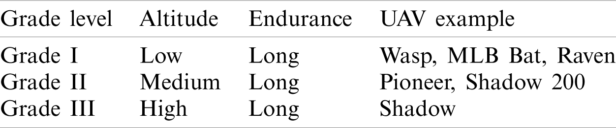
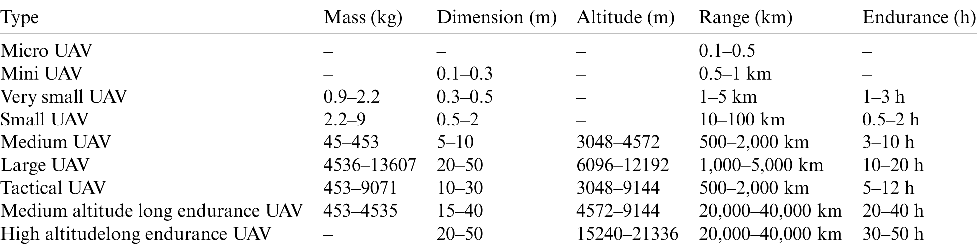
Table 2: UAV classification based on type
The general specifications of an UAV are determined during conceptual design phase to produce a satisfactory arrangement of UAV elements. The fundamental process in this stage is the “determination.” Nevertheless, there is a common analysis process without deep calculations. The design concept inputs are the requirements which include: tasks, fulfillment, robustness, control, charge, operational, duration, and manufacturing. Based upon which the necessary components are identified, these components represent the configuration of the UAV’s geometrical structure, engine, autopilot, ground station, etc. The output of this stage is the UAV configuration. The desired UAV configuration can be obtained by taking the various eligible components into consideration but eliminating any conflicting features. The geometric structure components refer to the fuselage, wings, horizontal, and vertical tail which are responsible for payload arrangements, lifting, longitudinal stability, and directional stability, respectively. The engine component generates the thrust which influences the performance and control of the UAV. On the other hand, the autopilot’s functions are steering, control and mission. The autopilot commands maneuverability and flight safety. As for the ground station, it controls and steers the UAV platform from the ground. Furthermore, the ground station impacts the autonomy and safety of flight [5]. According to the objectives of this study, we will focus on the navigation system only. In this paper, the task of selecting UAV-components to obtain the targeted solution for the desired application is presented. A reasoned planning is introduced with the objective to reach a consistent analysis of the required navigation to achieve the specification. These requirements represent various sensors and systems that can be assembled to obtain the required autonomy of UAV. In the initial stage the autonomy is categorized into levels which define the autonomy capabilities. In the next stage, various navigation systems terms are introduced which define the specific flight navigation modes. Next, the UAV navigation hardware and its compatibilities are identified. Finally, a case study is presented to discuss and implement the objective of this study the selection of appropriate UAV navigation components.
UAV autonomy is implemented as a solution to resolve the following problems: (1) existing physical barriers between the operator and the UAV, (2) latency which causes a delay in providing feedback, (3) limited data bandwidth available in the operational environment, and (4) the communication between the UAV and operators is susceptible to intentional or unintentional interference [6]. However, most UAV accidents are due to operator mistakes [7,8]. Thus, UAV autonomy is introduced as a practical solution to solve the mentioned shortfalls by reducing the operator’s interaction with the UAV. In this way, operator’s task is limited to supervising and focusing on the primary tasks through monitors and human machine interface devices which will result in a reduction of human errors. Generally, a UAV’s Level of Autonomy (LoA) can be categorized into six levels from level 1 (lowest) to level 6 (highest) as shown in Fig. 1. In level 1 there is no automation. The motion of the UAV is controlled entirely in manual mode by an operator without any obstacle avoidance ability. Level 2 represents a low automation approach in which the operator controls heading, altitude, and motion manually while GPS localizes the UAV. The degree of automation in level 3 is partial where the operator takes the responsibility of safe flight while the UAV can control heading, altitude, and motion automatically in certain situations. In both level 2 and level 3, the ability to avoiding obstacles is sense and alert only. As in level 3, the UAV in level 4 can control itself but the operator must be ready for interaction if any notification is received from the UAV. Compared with level 3, in level 4 the UAV can sense and avoid obstacles. On the other hand, level 5 has a high level of automation, thus eliminating the operator from the control operation. The UAV has additional systems which guarantee its operation when one of its systems fails. Level 6 is a full automation approach which incorporates artificial intelligence to control the UAV. In both level 5 and 6, the UAV can sense and navigate obstacles. Levels of autonomy allow determination of capabilities and hence required hardware components. The navigation system is one of the most critical components and as can be seen in Fig. 1, it plays an important role in determining the autonomy of the UAV.
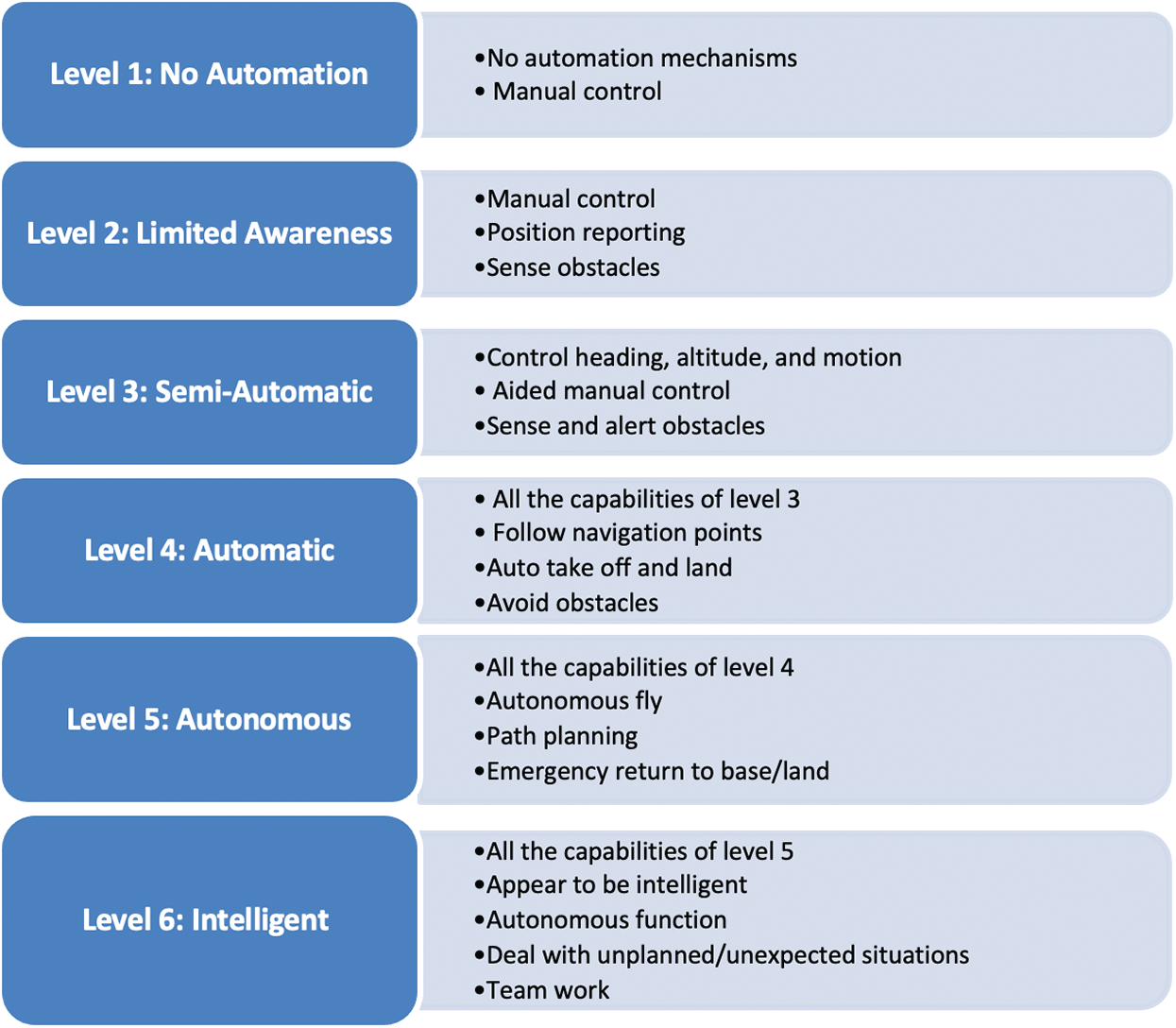
Figure 1: Capabilities of autonomy per level
The steps involved in the proposed methodology from the preprocessing stage to the implications of various factors, along with time-series is described in this section. In order to achieve the objective 1 (“detect if a node and/or a cluster is infected”), descriptive analysis in the form of mean and standard deviation were used. To further emphasis our findings, variances of these measures were compared using a F-test. Objective 2 (“differentiate between different types of applications”), which is related to different applications, was analyzed using a two-way ANOVA to understand whether there is an interaction between the virus and a variety of applications. Furthermore, objective 3 (“detect occupancy of a node and/or a cluster”), which is related to the occupancy of the node/cluster, can be predicted or identified using time-series based ARIMA method.
The architecture of the designed UAV system determines the LoA in demand to the needs of mission [9,10]. Thus, various navigation techniques for each LoA may be applied in UAV build. Generally, there are three navigation system types: electronics, inertial, and position fixing as shown in Tab. 3 [5].
Table 3: Navigation system types
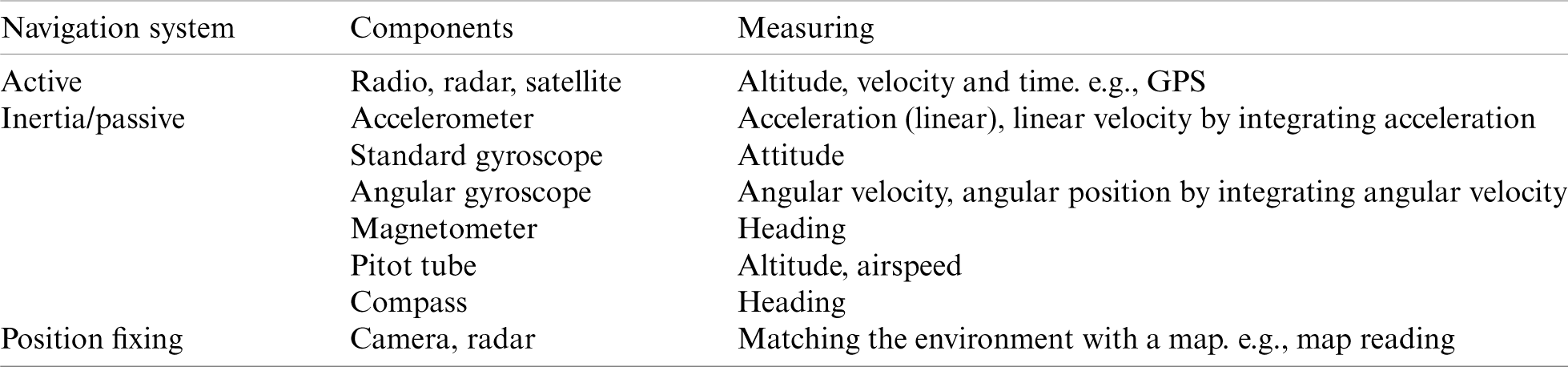
Active navigation systems rely on the echo of signals that they emit. Based on this, they can determine the position. On the other hand, passive navigation systems are affected by the electromagnetism of the earth. They take into account the change of state in order to determine their position. For example, assuming they are moving east at a speed of 10 m/s, then, after 10 s their location is going to be 100 m east from the old location. Finally, the position fixing sensors utilize a map to determine their position based on their knowledge of the map. For example, if the camera takes a photo of Eiffel tower, then the sensor is in Paris.
3 Technologies of UAV Navigation Systems
Navigation systems are devices used for measuring position and velocity. As explained in Section 2.1, in a UAV, navigation systems are essential for both high LoA “level 5 and level 6” in which the UAV itself should determine its exact location at any time and the lower LoA “level 2, level 3, and level 4” where the operators should know where the UAV at any time. This section will introduce a variety of navigation systems terms which are appropriate for flight navigation modes: GPS navigation (LoA: level 2), and autonomous navigation (LoA: level 3-level 6).
For an UAV platform, as shown in Fig. 2, there are twelve states which can be selected to represent the UAV system [11]. These states are explained in Tab. 4.
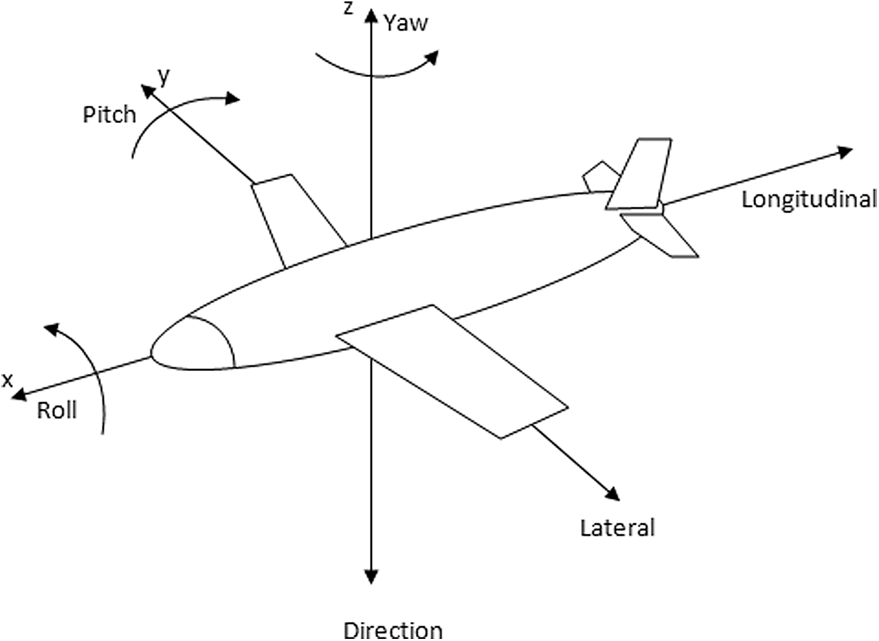
Figure 2: UAV platform coordinates

Sensors that can measure these states are Inertial and satellite based sensors. Summarizing these sensors, including their advantages and disadvantages, are presented in Tab. 5.
Table 5: State measurement sensors main properties
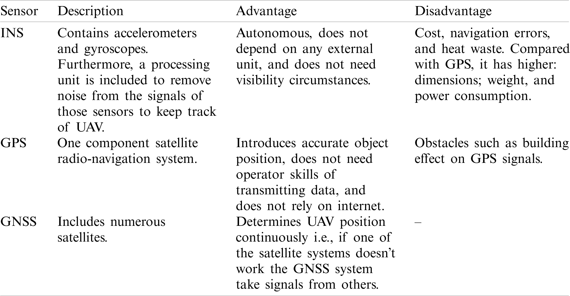
Inertial Navigation System (INS) enables the measuring of the UAV’s movement passively i.e., there is no need for any external operating part. The inertial sensors of INS have the essential feature that external disturbances, for example winds, do not affect their operation. Inertial sensors include accelerometers and gyroscopes. Linear acceleration, velocity, and position is measured from the accelerometer raw signal, first integral of signal, and second integral of signal, respectively. The angular is obtained from the gyroscope. By integrating gyroscope signals, the measurement of the angular position is realized [12]. The Global Positioning System (GPS) is the main way of determining the exact position, i.e., localization of UAVs [13,14]. For sensing a combination of position, navigation in time domain, Global Navigation Satellite System (GNSS) receivers are implemented [15].
3.2 Obstacle Avoidance Distance System
The term obstacle avoidance refers to the process of detecting obstacles, determining the distance between them and UAV, and turning around them when getting closer. An obstacle-avoidance system generally consists of three main units: sensing, detection, and resolution. The Sensing unit collects the around environment data by sensors. The detecting unit provides the UAVs ability of exposing future collision risks. In the beginning, distance data is estimated into the close future. Immediate and future distance data are then put together to identify collision metrics. By utilizing collision metrics, an indication is produced which determines whether an avoidance maneuver is necessary or not. The resolution unit is initiated in case of an existing close future collision. The resolution unit is essential to prevent a collision with obstacles by setting the appropriate maneuver (e.g., height, perpendicular, or changing speed maneuver) that should be implemented. After relieving obstacles, the UAVs should return back to their previous path [16]. Obstacle avoidance sensors are an essential component for enabling a targeted LoA from level 3 to level 6 in a potential environment. Examples of sensors in the sensing unit are: laser distance “LIDAR,” acoustic “SoNAR,” radar [17], and vision sensors which will be explained in the next subsection. The laser sensors provide planar distance, most of them, to the obstacle i.e., only obstacles within the plane of a UAV. Acoustic SONAR sensors can measure short range distance. On the other side, radar can measure both the position and speed of an obstacle. Summarizing all the above sensors, including their advantages and disadvantages, are presented in Tab. 6.
Table 6: Obstacle avoidance sensors main properties
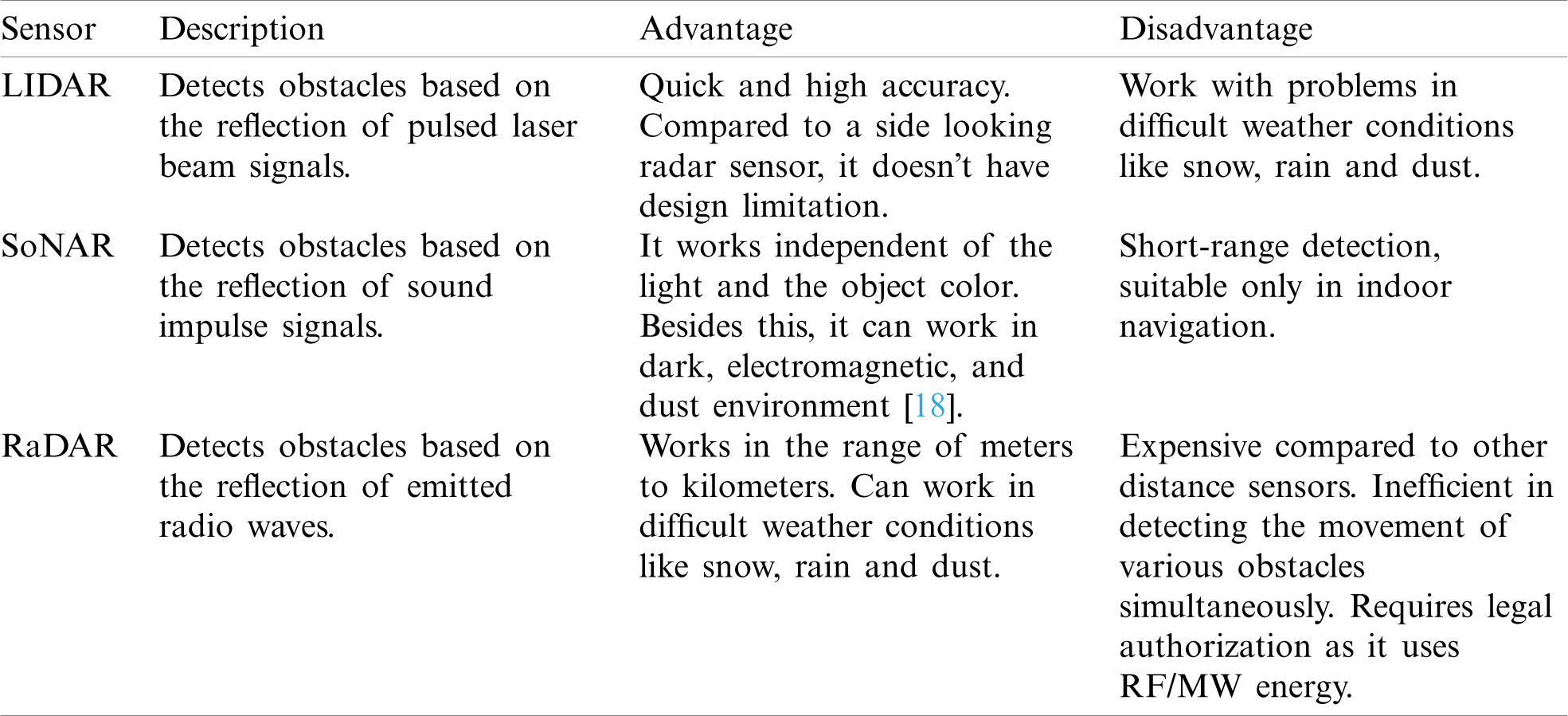
Different application domains require different sensor types. In difficult weather conditions, RaDAR outperforms LIDAR, but at a higher financial cost. Indoor applications use sonar and LIDAR but not RaDAR. Dusty environments favor sonar as the lasers of LIDAR may face reflexion/obstruction issues. LIDAR is mainly recommended for short distances in clear environments that require a high degree of accuracy. Sonar is preferred in dusty environments, even if highly reflecting materials are present. The RaDAR is the preferred option in case of large outdoor distances.
Recently, vision based approaches (camera analyzing images) have been introduced to navigation systems due to their low cost and weight. Moreover, compared with other sensors, vision sensors include quite contextual data [19]. They can obtain the various data of the environment such as color, depth, and other visual details [8]. Depth information can be determined using stereo vision sensor [20]. The RGB vision sensor can be implemented also as advanced technology to find the depth information in a per-pixel concept [21]. Details of vision sensor types and their features are shown in Tab. 7.
Table 7: Typical vision sensors
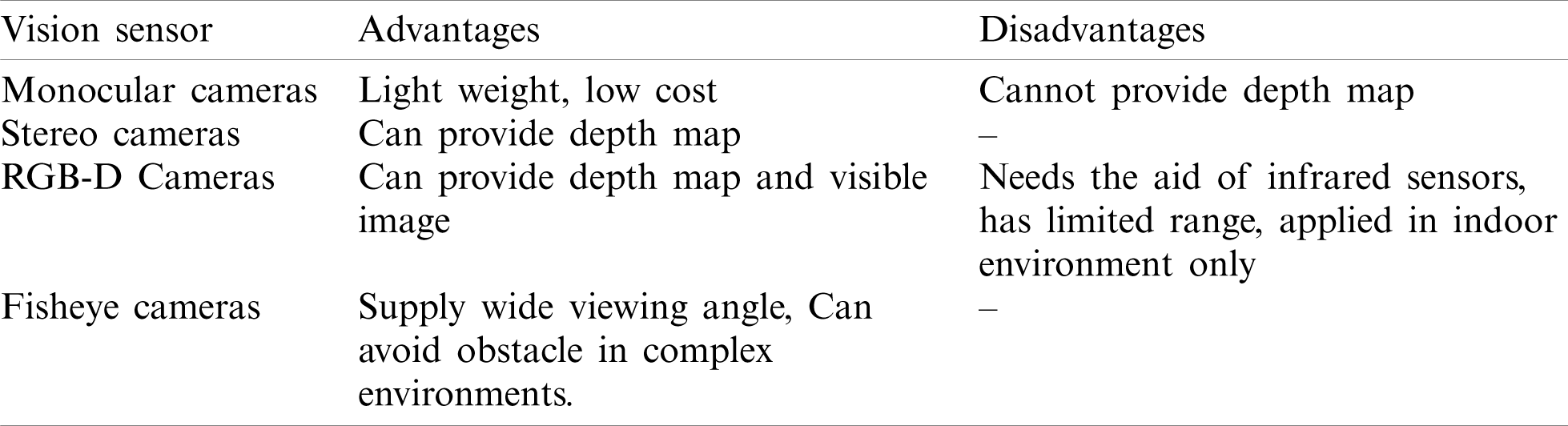
Electro-optical cameras and infra-red cameras have attractive characteristics including: small size, low cost, and lightweight. Thus, they are commonly applied sensors in UAVs. Electro-optical and infra-red cameras make the possibility of day-night and night visions, respectively.
Mapping is a technique of visualizing the navigation of an UAV in a way of interpreting the path of the UAV in the environment. Mapping systems can be either map-based or a map-building system. Map-based systems already have the environment data in a map format. The UAV uses these map information in its navigation. In complex environments where accurate map data is unavailable, map-building system can be implemented in which the maps are built during navigation e.g., using Simultaneous Localization and Mapping (SLAM) technique [8,22].
In SLAM, the localization concept refers to an estimation position, velocity, and attitude of an UAV which can be determined using inertial sensors. On the other hand, the term mapping indicates observing the environment. The observation process utilizes various potential sensors such as lasers, radars, and vision (infra-red, or visible light cameras). Thus, inertial or vision SLAM can be applied to estimate the navigation whilst generating a 3D map of the environment [23]. Generally, SLAM can be 2D or 3D. Whereby 2D SLAM uses a configuration sensor for distance with inertial, while 3D SLAM applies a configuration of vision with depth sensors [24]. An autopilot controls the UAV without any human interaction. Hence, it maintains the desired UAV orientation by utilizing the data from the various sensors to calculate corrective operations. The autonomy unit shown in Fig. 3 is responsible for the required autonomous behaviour e.g., returning home, targeting, etc. This section discusses the various technologies that can be used in UAVs. Section 4, discusses the specific hardware solution for each technology.
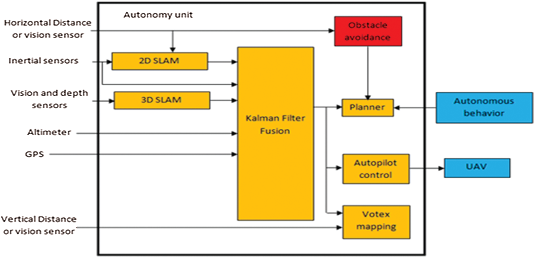
Figure 3: UAV autonomy unit module
4 UAV Navigation Hardware Solutions
Two main considerations are taken in navigation hardware of UAV; the first is the development in respect of high LOA. The second is the development of UAV to fly depending on vision sensors only. Considering the first approach INS, GPS, GNSS, LIDAR, SoNAR, RaDAR, and vision sensors are applied to support full autonomy. Due to the cost, weight, and rapid evolution of vision sensors; the second trend is applied photography cameras. They applied extremely in mapping and obstacle avoidance.
There are various UAV sensors which can measure the state of the UAV as mentioned in Section 3.1 and are readily available on the market. These sensors can be grouped under the following product types: INS, INS/GPS, and GNSS/INS. The INS device measures the states of the UAV. Generally, it has three accelerometers and three gyroscopes. Furthermore, some INS devices contain magnetometers to measure the heading of UAV [25]. The main characteristics of the INS performance are related to the features of the implemented sensors [26]. To overcome the drawbacks of state measurement sensors mentioned in Tab. 4 by using INS or GPS alone, a combination of GPS/INS is applied to improve the accuracy and sampling rate of position, velocity, and attitude. Besides this, an extended or unscented Kalman Filter has been applied to filter issue of GPS/INS sensor fusion [22]. This configuration can also be implemented by combining GNSS with INS. Tab. 8 summarizes some of the INS, INS/GPS, and INS/GNSS products which are available in the market.
Table 8: Some state measurement technology makers and products
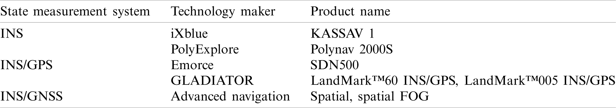
Selecting the optimal state measurement system is a complex process and many factors have to be taken into consideration. These factors represent the performance, interface, technology makers, weight, size, and cost.
4.2 Obstacle Avoidance Sensors
Obstacle avoidance technology was previously limited to obstacles in front of UAVs only using traditional sensors such as SonAr and LiDAR. Recently, developments in obstacle avoidance sensor technology enable UAVs to detect all obstacles around the UAVs in all directions. There are various obstacle-avoidance hardware solutions available produced by various companies [25,26] such as: stereo vision sensors and Time-of-Flight (ToF) cameras. Detecting the same obstacle using two cameras is implemented as a hardware solution to enable obstacles to be visualized in 3D. This technique is referred to as stereo vision. Two cameras are mounted at a fixed distance apart. Hence, by analysing the same captured simultaneous images of the two cameras; the depth of the obstacles can be measured [27]. Current technology developed by e-con Systems is stereo vision camera “STEEReoCAM” with resolutions of up to 1600
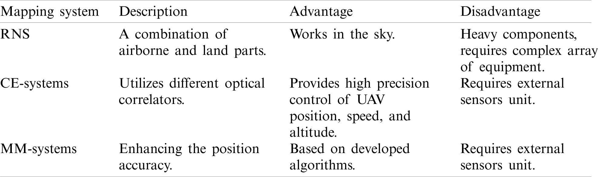
Researchers from MIT Computer Science and Artificial Intelligence Laboratory have recently released a new mapping technique called Nano Map for use in fast UAVs operating in complex environments. NanoMap as is a further development of the SLAM process, but has implemented 3D depth sensors to carry out fast navigation, up to 9 m/s, in dense environments [29]. Radio navigation system (RNS) is applied to identify the current position using radio frequencies and transmit data wirelessly between the ground and the UAV [30,31]. On the other hand, a satellite navigation system (SNS) is applied to measure the position and altitude of the UAV using data from multi-satellites [30,32]. Correlated-extremal systems (CE-systems) utilize different optical correlators for identifying UAV position in real time [30,33]. A summary of the mapping systems, including their advantages and disadvantages, is presented in Tab. 9.
Table 9: Mapping systems main properties
This section presents a number of hardware solutions which implement various navigation technologies. The next section presents a step by step process for selecting the appropriate components.
5 Selecting Appropriate UAV Navigation Components
In this section, a four stages selection process is suggested for designing the UAV navigation system architecture. The first stage determines the autonomy level (as explained in Section 2.1) based on the application domain. In the second stage, the UAV developer selects the essential navigation system technologies (as explained in Section 3) based on the level of autonomy determined in stage 1. Stage 3 identifies the hardware components (explained in Section 4) from the list of components implementing the selected technologies from the previous stage. Finally, stage 4, evaluates the UAV navigation system configuration to ensure compatibility between the selected hardware components and their interfaces. Fig. 4 summarizes the component selection process.
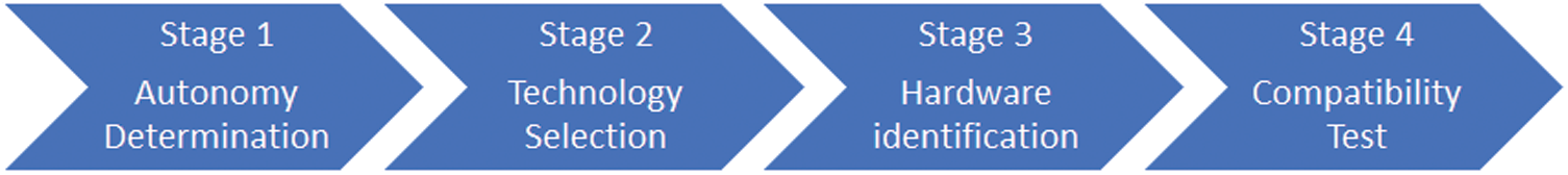
Figure 4: UAV navigation components selection
The above, aims to simplify the component selection process. The stages are explained in detail in the sub-sections below.
5.1 Stage 1: UAV Application Consideration
Determining the appropriate autonomy level is essential for designing an appropriate UAV navigation system that meets the requirements of its application domain. Fig. 5 introduces six levels of autonomy of and their corresponding functionality, starting at level 1—no autonomy, to level 6—highest degree of autonomy.
Level 1 UAVs are fully controlled by human users and are mainly used for recreation activities. Level 2 UAVs are also manually controlled but with feedback to the operator’s controller and are therefore most commonly used for relatively simple business tasks, such as inspection and maintenance. Level 3 UAVs have a high degree of automation and require human control only for task assignment and aid. Such UAVs are used in mapping, seeding, and spraying tasks. They have a multitude of applications in agriculture and automated inspection. Level 4 UAVs have all the capabilities of the level 3 UAVs but with automated takeoff/landing and navigation. These UAVs only need task assignment from the operator, and they can complete their task alone. Most of these UAVs are used for surveying, taking photographs and videos of certain areas. For example, they can inspect the progress of a construction site. Level 5 UAVs are fully autonomous and they do not require human users. They are capable of carrying out complex missions. Most of them are currently used for defence applications. Level 6 UAVs are still at the experimental stage. Like level 5 UAVs, they are completely autonomous. However, they can deal with unexpected situations, learn from past experience (Artificial Intelligence) and also operate as part of a team [34].
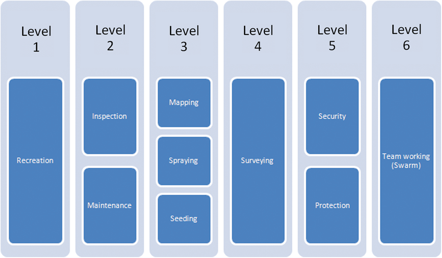
Figure 5: Autonomy levels based on application domain
5.2 Stage 2: Navigation Sensors Technology
One of key components in UAV development is the sensors. Sensors give the UAV the capabilities to perform the various tasks. Fig. 6 shows the sensor technologies included in each level.
Level 1 does not require any advanced sensors. Level 2 requires position sensors such as GPS and distance sensors to sense the obstacles. Level 3 requires all the Level 2 sensors but in addition a Gyroscope, accelerometer, magnetometer are required in order to control the heading and position of the UAV. Level 4, additionally requires vision sensors and more advanced mapping systems such as GNSS. They also have a microcontroller that can process the inputs from all these sensors and make some basic decisions. Level 5 requires an even more capable microcontroller as it includes more complex processing including image recognition. Level 6 is similar to level 5 but it needs to communicate with the other UAVs in order to collaborate on a task. Currently, level 5 and 6 UAVs require a powerful controller with a high power necessity. However, this may change to some degree in the near future as 5G can allow the UAV to send all the information to a land station for processing and control. Hence the need for a powerful microcontroller will be minimized [35,36].
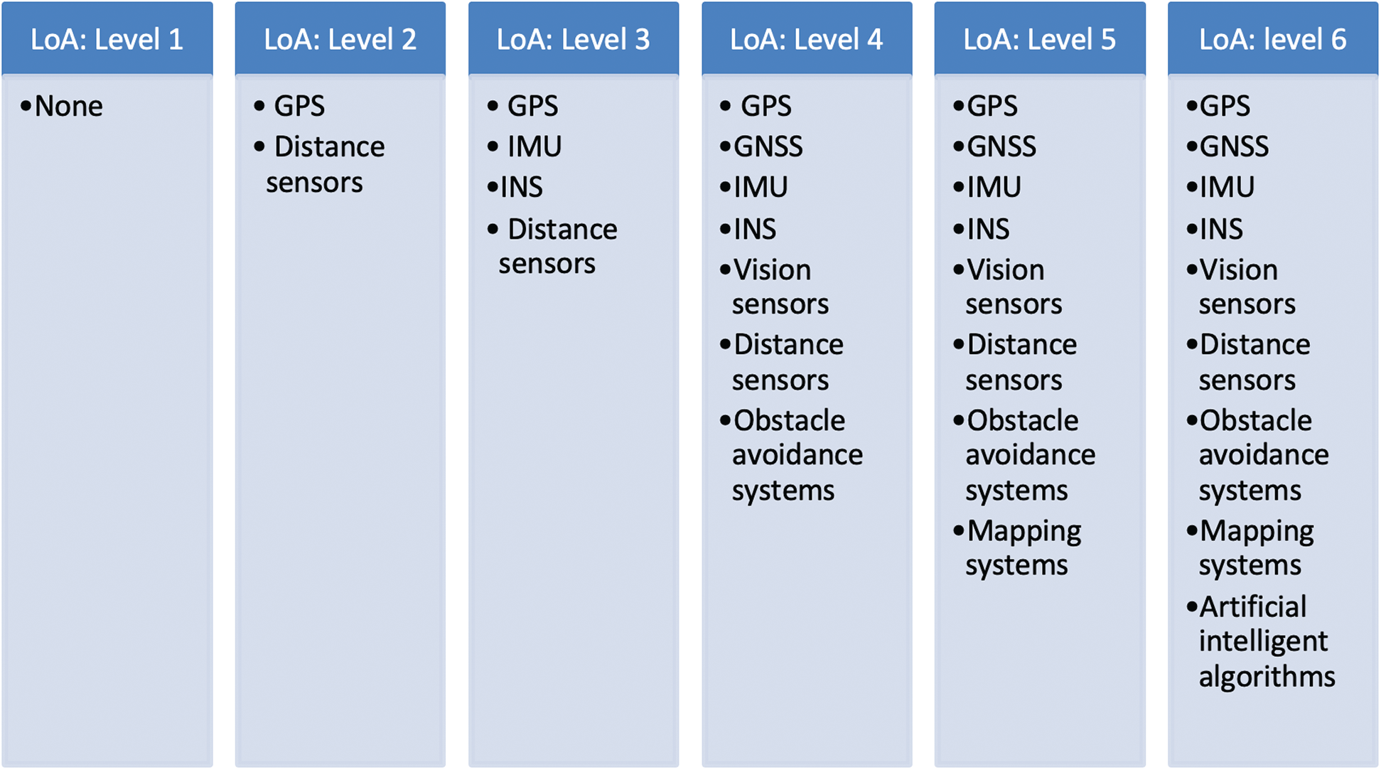
Figure 6: List of sensors included in each level
5.3 Stage 3: Hardware Components
Selecting the appropriate components is one of the most important aspects of UAV design. In this paper, we propose a simple but accurate method for selecting the most appropriate navigation sensors based on task requirements and environmental needs. Fig. 7 presents the selecting flow for picking the navigation sensors.
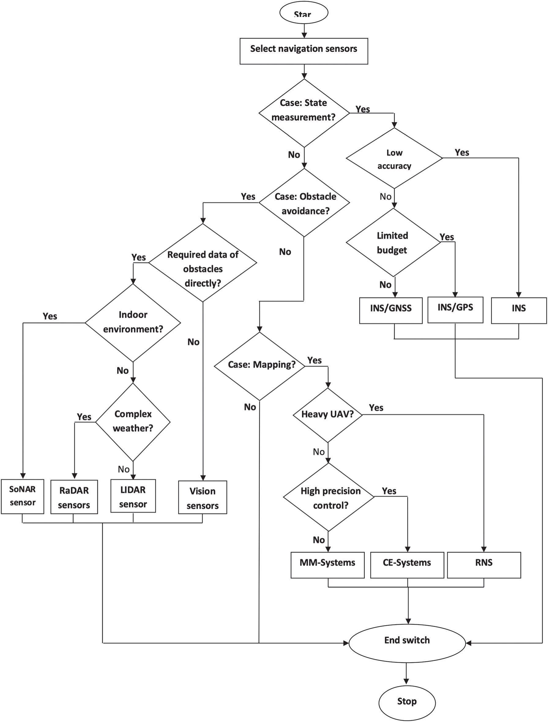
Figure 7: Selection stage of navigation sensors
The proposed selection strategy, presented in the flowchart in Fig. 7, presents a procedure for selecting appropriate sensors for: state measurement, obstacle avoidance and mapping. The selection is based on multiple application criteria and sensor properties. The main selection criteria for state measurement sensors include accuracy and cost. Low accuracy, INS can be chosen directly. If accuracy is important in the UAV’s application, then INS/GPS or INS/GNSS must be selected. If the UAV is designed with low cost components the INS/GPS is selected. In contrast, INS/GNSS can be applied for high cost UAVs. Regarding obstacle avoidance sensors, if the customer does not need to obtain the data directly then vision sensors can be applied. If information about the obstacles is important and needs to be obtained directly, then sonar sensors can be applied for indoor applications. In case of outdoor applications, if the environment is complex, then RaDAR is chosen. For a non complex environment, a LIDAR sensor is selected. If the UAV requires mapping capabilities within limited weight, i.e., heavy UAV, RNS can be applied. In limited weight UAV, if high precision mapping is important then CE-systems is the default option. If precision is not important, MM-systems can be chosen.
The vision sensor is also a very important component that can affect the performance of the UAV in many ways. Selecting the vision sensor is a tradeoff between, size, weight, power consumption, image quality, frame rate, stability and night vision. The type of vision sensor is selected according to Fig. 8.
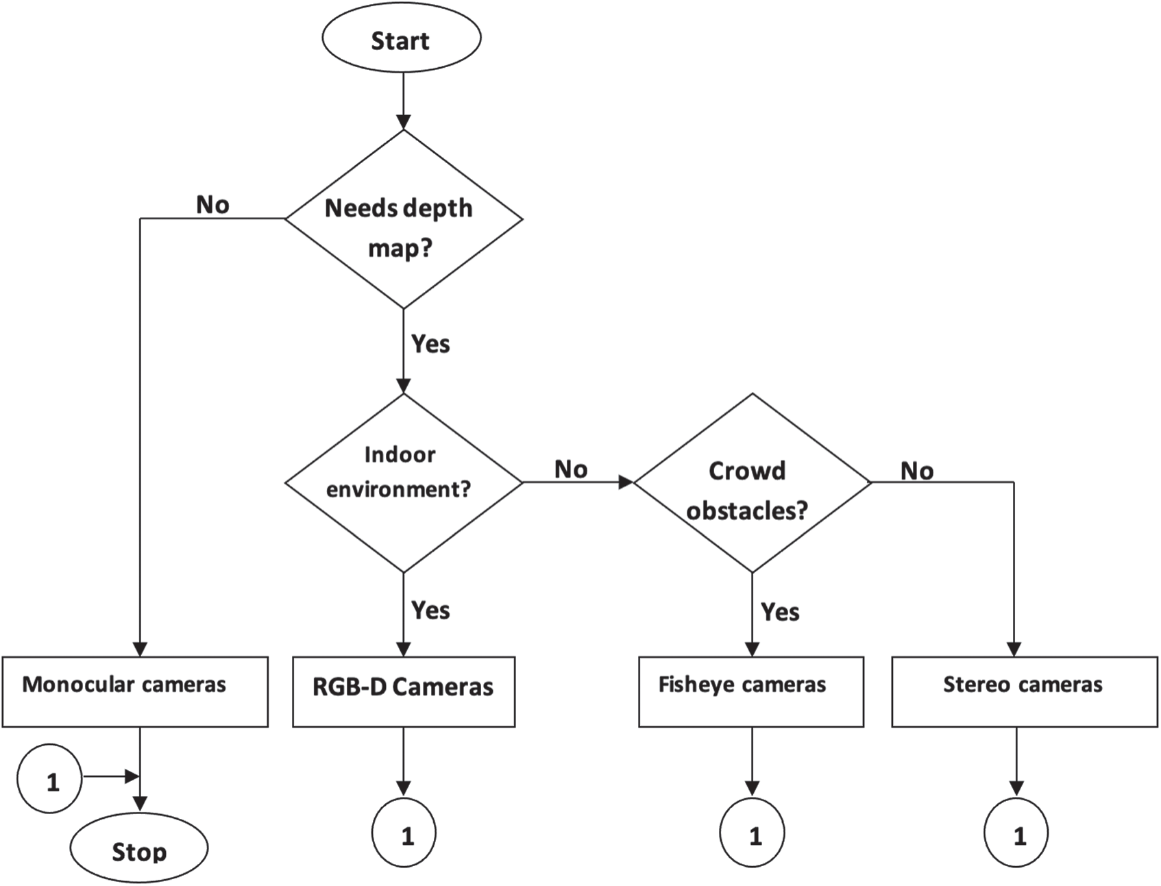
Figure 8: Algorithm of vision sensor selection
As it can be seen in the flowchart in Fig. 8, if no depth mapping is required, then monocular cameras can be used. On the other hand, if depth mapping is required and it is an indoor application then RGB-D cameras can be used. Else if the UAV will be dealing with a lot of obstacles then Fisheye cameras must be selected. Otherwise a stereo camera can be applied.
5.4 Stage 4: Hardware Compatibility
When specific components are selected, their compatibility with each other should be checked. In this research, hardware compatibility refers to the compatibility of the UAV components with each other. In more detail, their compatibility with a particular controller unit, ESC (electronic speed controller), connection interfaces, power consumption and frequency. In terms of compatibility, we mainly check the following:
a) The interfaces: The interfaces of both the sensors and the controller should be compatible.
b) Power consumption requirements: The UAV should have sufficient power to feed the sensor.
c) Shape, Size and Weight: The physical properties of the sensor such as its size, shape and weight should also be checked for compatibility with the design and flyweight capabilities of the UAV.
d) Redundancy: It is possible that some sensors include the capabilities of some other sensors. For example an 11 Axis IMU, includes accelerometer, gyroscope, magnetometer, pressure meter and GPS. Hence there is no need for a separate gyroscope sensor.
The compatibility check should be followed by other checks, such as cost and reputation of certain components before the selection is made. However, as these are non technical criteria, they are not covered in this research.
This section includes a case study that demonstrates step by step (Fig. 4), the use of the proposed framework. In this case study we want to develop a low cost, outdoors UAV for seeding. The first step is to decide its level of autonomy. The diagram in Fig. 5 can help with this task. The appropriate level of autonomy for the seeding UAV is level 3. This is because neither team work nor a high level of autonomy is required. It will be operating in a rural environment, without a lot of obstacles and it does not have to deal with new unexpected situations. The next step is to determine the appropriate sensor technologies. GPS, IMU, INS, and distance sensors are the potential sensors that may be used according to Fig. 6. The next step is to select the appropriate hardware solutions. Depending on the flowchart of Fig. 7, the INS is selected for a low cost state measurement sensor with GPS separately. Besides this, the vision sensor is applied in detecting obstacles as since taking the direct information of obstacles is not important during the seeding process. The type of vision sensor is selected dependent on Fig. 8. Because the depth of vision is not required, monocular cameras are selected. In summary, as shown in Fig. 9, the navigation system of UAV for seeding will include: (1) INS, (2) GPS, and (3) monocular cameras.
Finally, all the sensors must be checked for compatibility in terms of interfacing with the control board, power consumption, shape, size and weight. For this purpose, Kalman filters are applied to enhance the performance of INS and GPS when operating together. Hence, the INS is integrated with GPS as shown in Fig. 10 in one model to overcome the issue of weak GPS signals.
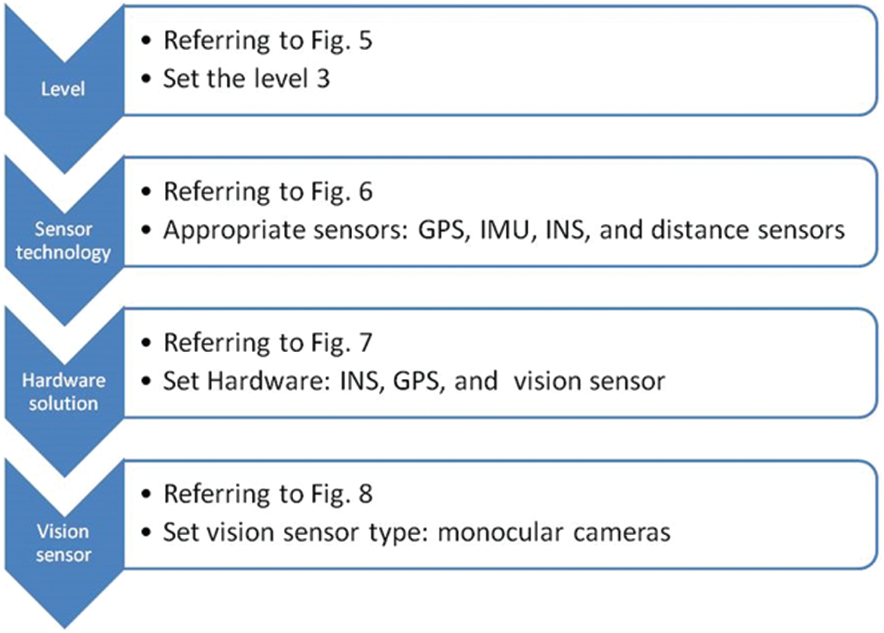
Figure 9: The scenario of selecting navigation system
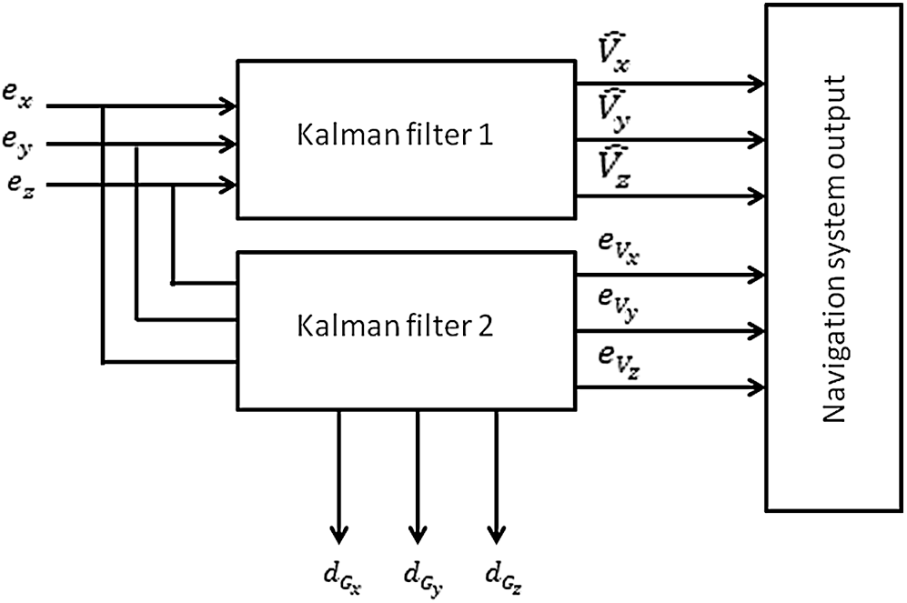
Figure 10: Block diagram of integrating INS/GPD
The inputs of this model are the errors resulted from subtracting the velocities measured by the GPS from the ones measured by INS as follows
where Vx, Vy, Vz denotes the measured velocities in the direction of x-axis, y-axis, z-axis, respectively. These errors are fed to the inputs of the two kalman filters. For weak GPS signals where these errors are not zero, the kalman filters start working to predict these weak signals. The first Kalman filter, i.e., Kalman filter 1, estimates the INS velocity (
where T is the vector of measurement, A is the design matrix, and n is the vector of noise of measured signal of type white Gausian. Xk is the vector of states which includes the errors of altitude (eAz), velocity (eVx, eVy, eVz), and the drift of gyroscopes (dGx, dGy, dGz). In the case of disappear the GPS signal, the INS supply data of position till the signal of GPS appear again.
This paper proposes a framework for selecting UAV navigation sensors. This was done in a four step process, where the developers must first decide the requirements based on the level of the UAV. UAVs were divided into six levels based on their capabilities. The applications domain for each level was also explained in this paper. Once the developers decide on the application the next step is to select the sensors components. Then the specific hardware should be selected, followed by a compatibility check between the sensors and the controller. The proposed framework was demonstrated by the use of a case study for a low cost, outdoors UAV application.
Funding Statement: The authors received no specific funding for this research study.
Conflicts of Interest: The authors declare that they have no conflicts of interest to report regarding the present study.
1. H. Q. Pham, M. Camey, K. D. Pham, K. V. Pham and L. R. Rilett, “Review of unmanned aerial vehicles (UAVs) operation and data collection for driving behavior analysis,” CIGOS 2019, Innovation for Sustainable Infrastructure, Lecture Notes in Civil Engineering, vol. 54, pp. 1111–1116, 2020. [Google Scholar]
2. D. Giordan, M. S. Adams, I. Aicardi, M. Alicandro, P. Allasia et al., “The use of unmanned aerial vehicles (UAVs) for engineering geology applications,” Bulletin of Engineering Geology and the Environment, vol. 79, no. 7, pp. 3437–3481, 2020. [Google Scholar]
3. F. Cazaurang, K. Cohen and M. Kumar, Multi-Rotor Platform Based UAV Systems, 1st ed., USA: ISTE Press, Elsevier, 2020. [Google Scholar]
4. G. Singhal, B. Bansod and L. Mathew, “Unmanned aerial vehicle classification, applications and challenges: A review,” Preprints Journal, vol. 10, pp. 1–19, 2018. [Google Scholar]
5. M. Sadraey, “Unmanned aircraft design: A review of fundamentals synthesis lectures on mechanical engineering,” Synthesis Lectures on Mechanical Engineering, vol. 1, no. 2, pp. i–193, 2017. [Google Scholar]
6. M. Protti and R. Barzan, “UAV autonomy–which level is desirable?–which level is acceptable? Alenia aeronautica viewpoint,” in Platform Innovations and System Integration for Unmanned Air, Land and Sea Vehicles (AVT-SCI Joint SymposiumFlorence, pp. 1–12, 2007. [Google Scholar]
7. E. Petritoli, F. Leccese and L. Ciani, “Reliability and maintenance analysis of unmanned aerial vehicles,” Sensors, vol. 18, no. 9, pp. 3171–3187, 2018. [Google Scholar]
8. Y. Lu, Z. Xue, G. S. Xia and L. Zhang, “A survey on vision-based UAV navigation,” Geo-Spatial Information Science, vol. 21, no. 1, pp. 21–33, 2018. [Google Scholar]
9. A. Renault, “A model for assessing UAV system architectures,” Procedia Computer Science, vol. 61, pp. 160–167, 2015. [Google Scholar]
10. B. Stark, C. Coopmans and Y. Chen, “Concept of operations of small unmanned aerial systems: Basis for airworthiness towards personal remote sensing,” In: K. Valavanis, G. Vachtsevanos (Eds.) Handbook of Unmanned Aerial Vehicles, Dordrecht: Springer, 2015. [Google Scholar]
11. Z. Tahir, W. Tahir and S. A. Liaqat, “State space system modelling of a quad copter UAV,” Indian Journal of Science and Technology, vol. 9, no. 27, pp. 1–5, 2016. [Google Scholar]
12. T. T. Nwe, T. Htike, K. M. Mon, Z. M. Naing and Y. M. Myint, “Application of an inertial navigation system to the quad-rotor UAV using MEMS sensors,” Engineering and Technology, vol. 42, pp. 578–582, 2008. [Google Scholar]
13. J. Kwak and Y. Sung, “Autonomous UAV flight control for GPS-based navigation,” IEEE Access, vol. 6, pp. 37947–37955, 2018. [Google Scholar]
14. S. Ashraf, P. Aggarwal, P. Damacharla, H. Wang, A. Y. Javaid et al., “A low-cost solution for unmanned aerial vehicle navigation in a global positioning system-denied environment,” International Journal of Distributed Sensor Networks, vol. 14, no. 6, pp. 1–17, 2018. [Google Scholar]
15. J. Jang, W. G. Ahn, S. Seo, J. Y. Lee and J. P. Park, “Flight test result for the ground-based radio navigation system sensor with an unmanned air vehicle,” Sensors, vol. 15, no. 11, pp. 28472–28489, 2015. [Google Scholar]
16. I. Mahjri, A. Dhraief and A. Belghith, “A review on collision avoidance systems for unmanned aerial vehicles,” in Int. Workshop on Communication Technologies for Vehicles, Sousse, Tunisia, Cham: Springer, pp. 203–214, 2015. [Google Scholar]
17. J. García and J. M. Molina, “Simulation in real conditions of navigation and obstacle avoidance with PX4/Gazebo platform,” in Proc. IEEE Int. Conf. on Pervasive Computing and Communications Workshops (PerCom WorkshopsKyoto, Japan, pp. 979–984, 2019. [Google Scholar]
18. M. Guanglei and P. Haibing, “The application of ultrasonic sensor in the obstacle avoidance of quad-rotor UAV,” in Proc. IEEE Chinese Guidance, Navigation and Control Conf. (CGNCCNanjing, pp. 976–981, 2016. [Google Scholar]
19. B. Park and H. Oh, “Vision-based obstacle avoidance for UAVs via imitation learning with sequential neural networks,” International Journal of Aeronautical and Space Sciences, vol. 21, no. 3, pp. 768–779, 2020. [Google Scholar]
20. P. Kolar, P. Benavidez and M. Jamshidi, “Survey of datafusion techniques for laser and vision based sensor integration for autonomous navigation,” Sensors, vol. 20, no. 8, pp. 2180, 2020. [Google Scholar]
21. W. G. Aguilar, S. Morales, H. Ruiz and V. Abad, “RRT* GL based optimal path planning for real-time navigation of UAVs,” in Proc. Int. Work-Conf. on Artificial Neural Networks, Cadiz, Spain, Cham: Springer, pp. 585–595, 2017. [Google Scholar]
22. G. N. Desouza and A. C. Kak, “Vision for mobile robot navigation: A survey,” IEEE Transactions on Pattern Analysis and Machine Intelligence, vol. 24, no. 2, pp. 237–267, 2002. [Google Scholar]
23. Z. Sjanic, “Navigation and mapping for aerial vehicles based on Inertial and imaging sensors,” Ph.D. Dissertation, Linköping University, Sweden, 2013. [Google Scholar]
24. S. Saeedi, C. Thibault, M. Trentini and H. Li, “3D Mapping for autonomous quadrotor aircraft,” Unmanned Systems, vol. 5, no. 3, pp. 181–196, 2017. [Google Scholar]
25. SBG systems, “SBG Systems–Inertial navigation systems, IMU, AHRS, MRU,” 2020. [Online]. Available: https://www.sbg-systems.com. [Google Scholar]
26. N. Abbate, A. Basile, C. Brigante, A. Faulis and F. L. Rosa, “Modern breakthrough technologies enable new applications based on IMU systems,” Journal of Sensors, vol. 2011, no. 2, pp. 1–7, 2011. [Google Scholar]
27. J. N. Yasin, S. A. S. Mohamed, M. H. Haghbayan, J. Heikkonen, H. Tenhunen et al., “Unmanned aerial vehicles (UAVsCollision avoidance systems and approaches,” IEEE Access, vol. 8, pp. 105139–105155, 2020. [Google Scholar]
28. M. Ball, “E-con systems launches stereo vision camera for NVIDIA platforms,” 2020. [Online]. Available: https://www.unmannedsystemstechnology.com/2018/09/e-con-systems-launches-stereo-vision-camera-for-nvidia-platforms/. [Google Scholar]
29. SPAR3D, “Because SLAM is too slow for fast drones,” 2018. [Online]. Available: https://www.spar3d.com/blogs/the-other-dimension/nanomap-slam-slow-fast-drones/. [Google Scholar]
30. A. V. Nebylov and J. Watson, Aerospace Navigation Systems, USA: John Wiley & Sons, 2016. [Google Scholar]
31. J. Gundlach, Designing Unmanned Aircraft Systems: A Comprehensive Approach, 2nd ed., USA: American Institute of Aeronautics and Astronautics, 2014. [Google Scholar]
32. UAV Navigation, “UAV Navigation cutting-edge autopilots,” 2020. [Online]. Available: https://www.uavnavigation.com. [Google Scholar]
33. O. N. Strangul’ and V. P. Tarasenko, “Correlation-extremal systems for navigation and location of mobile objects,” Automation and Remote Control, vol. 62, no. 7, pp. 1204–1211, 2001. [Google Scholar]
34. A. Israr, M. Ashraf, S. Jan and F. Q. Khan, “Detection and minimization of jamming attacks to enhance string stability in VANETs,” Journal of Information Communication Technologies and Robotic Applications, vol. 10, no. 2, pp. 9–17, 2019. [Google Scholar]
35. S. Jan, O. B. Tauqeer, F. Q. Khan, G. Tsaramirsis, A. Ahmad et al., “A framework for systematic classification of assets for security testing,” Computers, Materials & Continua, vol. 66, no. 1, pp. 631–645, 2021. [Google Scholar]
36. F. Q. Khan, S. Rasheed, M. Alsheshtawai, T. M. Ahmed and S. Jan, “A comparative analysis of RAD and agile technique for management of computing graduation projects,” Computers, Materials & Continua, vol. 64, no. 2, pp. 777–796, 2020. [Google Scholar]
 | This work is licensed under a Creative Commons Attribution 4.0 International License, which permits unrestricted use, distribution, and reproduction in any medium, provided the original work is properly cited. |