DOI:10.32604/cmc.2021.016741
| Computers, Materials & Continua DOI:10.32604/cmc.2021.016741 | |
| Article |
Experimental Study of Heat Transfer Enhancement in Solar Tower Receiver Using Internal Fins
1Education Sector in Jubail, Jubail Technical Institute, Jubail Industrial City, 31961, Saudi Arabia
2Mechanical Engineering Department, College of Engineering, Universiti Tenaga Nasional, Kajang, 43000, Selangor, Malaysia
3Power Generation Unit, Institute of Power Engineering (IPE), Universiti Tenaga Nasional, Kajang, 43000, Selangor, Malaysia
*Corresponding Author: Hashem Shatnawi. Email: hashem121@yahoo.com
Received: 10 January 2021; Accepted: 19 February 2021
Abstract: The receiver is an important element in solar energy plants. The principal receiver’s tubes in power plants are devised to work under extremely severe conditions, including excessive heat fluxes. Half of the tube’s circumference is heated whilst the other half is insulated. This study aims to improve the heat transfer process and reinforce the tubes’ structure by designing a new receiver; by including longitudinal fins of triangular, circular and square shapes. The research is conducted experimentally using Reynolds numbers ranging from 28,000 to 78,000. Triangular fins have demonstrated the best improvement for heat transfer. For Reynolds number value near 43,000 Nusselt number (Nu) is higher by 3.5% and 7.5%, sequentially, compared to circular and square tube fins, but varies up to 6.5% near
Keywords: Solar tower power; external receiver; longitudinal internal fins; thermocouples; temperature gradient
Solar thermal power plants are a set of technologies that acquire heat from sunlight by mirroring concentrated emission of sun rays to medium fluid in order to produce heat which in turn is used to generate electricity.
Solar power towers are the most suitable systems for handling processes having high temperature. Such systems are able to reach excessive solar flux, usually higher than 600 sun (

Figure 1: Solar power tower plant
The receiver utilised in industrial solar power plants is called external tube receiver. This external receiver is regarded as a major element of the solar power tower plant. While half of the tube’s circumference is heated by sun rays that are reflected from heliostats, the remaining half is considered adiabatic. The receiver’s efficiency is essential for the overall efficiency of the energy captured, and thus this represents a crucial area of research [1].
One of the major problems of these solar power tower plants with various HTFs (heat transfer fluids) is the life span and reliability estimation of principal receivers. These receivers must endure high operating temperatures, decomposition and high solar flux causes fatigue and thermal pressures. Hence, it is crucial to optimise these receivers’ design to improve their efficiency.
Maximisation of the thermal efficiency of the receiver can be done by decreasing the region exposed to sun rays by reducing size of the receiver as much as possible to reduce thermal losses through convection, radiation, conduction and reflection and by optimising wall thickness and size diameter of the tubes to reduce thermal stresses produced by the thermal gradients along the tube circumference and thickness [2].
Recently, several efforts have been expended on the optimisation of the receiver design so as to reduce thermal losses and early breakdown of the tubes, and also to increase the receiver’s energy conversion efficiency. Nevertheless, no studies have investigated the effect of adding fins along the receiver on its thermal performance. The research objective is to examine the thermal properties of the central receiver’s new design. Also, the research aims to examine the heat transfer properties of water as an HTF (heat transfer fluid) in the tube with fins. As a result, a new receiver can be designed that performs better than the traditional receiver, reduce heat losses by using tubes with small diameter supplemented with fins to reduce the external region exposed to sunlight.
The HTF (heat transfer fluid) that goes through the receiver is different for different plant designs. As a pure energy conductor, liquefied molten salt with benefits of excellent chemical stability and huge thermal capacity has become an essential working fluid for focusing solar power compared to other HTFs, while the water is plenty and cheap and has several particularly desired attributes. Selection of the HTF depends on several factors such as high boiling point, low melting point, high heat conductivity, high specific heat capacity, low viscosity, non-polluting, non-flammable, and low cost, and also compatible with other materials [3]. Comparison of different heat transfer fluids is shown in Tab. 1.
Table 1: Assessment of heat transfer medium [4]

Tubes with internal fins have the benefit, in comparison to smooth tubes, of providing more heat transfer region per unit tube length [5]. Maytorena et al. [6] examined steam generation numerically in a vertical tube which receives concentrated solar rays, after the increase in the concentrated heat flux by 40% and the steam output mass flow increased four times. An experimental research was conducted with a finned receiver inside a solar tower system by researchers Piña-Ortiz et al. [7]. The system was equipped with 1232 small cylindrical-shaped fins with diameter 0.0095 m and length 0.09 m. The vertical wall received a constant water flow which eliminated the absorbed radiation energy. It was discovered that the receiver’s maximum heat transfer efficiency was 94.4%, and it decreased with the increase in the radiative flux.
Chang et al. [8] experimentally examined the performance of heat transfer of water for solar absorber of stainless steel within Reynolds number ranging from 10000.0 to 35000.0 with non-consistent heat flux. This outcome suggests that the Dittus–Boelter association is still available to compute the transfer of heat in an absorber tube having uneven heat flux. López-Martín et al. [9] proposed an outdoor test-bed created to determine the optical efficiency of solar receiver tubes under actual sunlight conditions with de-mineralised water as an HTF (heat transfer fluid) and a receiver made of stainless steel. The optical efficiency was found to be 92%.
Yu et al. [10] built a dynamic replica of Beijing’s 1 MWe Solar Tower Power Plant, which included the heliostat field, the principal receiver system (steam/water). The outcomes confirmed that the experimental conditions and the simulation results were remarkably aligned. The simulation model can present an entire virtual platform to conduct the research scheme with a comparatively good precision instead of the actual plant so as to lower the hazard.
Amina et al. [11] numerically examined the transfer of heat in a parabolic trough collector receiver having longitudinal fins by using different types of nanofluid, with an effective temperature of 573 K. A substantial heat transfer improvement is obtained when the Reynolds number falls in the range
Liu et al. [13] numerically investigated a single-phase heat transfer improvement in tubes with internal fins having height 0.5 mm. The outcomes of the research suggest that the fins’ shape has a small influence on the heat transfer and flow, and the triangular fins have the best effect on the heat transfer. Shatnawi et al. [14] studied the effect of fins shape numerically with the same area of the inner surface and the same flow rate, the performance of triangular fins registered the highest Nusselt number.
Baba et al. [15] experimentally evaluated improvement in heat transfer and dropped in pressure in double piped tube receiver with internal fins by using nanofluids and evaluated the results of this research with basic tube heat exchanger. The outcomes suggest that the rate of heat transfer is 80%–90% more compared to that of the basic tube heat exchanger. Often, geometrically altered fins are included, which, apart from increasing heat exchanger’s surface area density, enhance the coefficient for convection heat transfer.
The objective of this research is to obtain a solar thermal power generation mechanism that can be comparable with traditional power generation technologies. By constructing an innovative solar tower receiver which can work efficiently with high temperatures by minimising the thermal losses by using small finned tubes, we can provide greater performance than traditional receivers. Experimental research is employed to study the designed receiver performance. In this experimental study, an innovative design of solar receiver which is based on internal fins pipes is suggested so as to improve its mechanical and thermal behavior under operational conditions.
2.1 Experimental System and Method
The experimental model used to examine the heat transfer characteristics of solar receiver is constructed at JTI (Jubail Technical Institute). The experimental unit is displayed in Fig. 2. Essentially, the system consists of one primary loop with two water tanks for hot and cold water. Water was disseminated from a 1000 litre room temperature tank for storage (cold tank). This tank was provided water through a normal flow from another tank of 1000 L (hot water) after which the temperature reduced normally. A pump of variable speed (Grundfos SCALA2) is employed, which quickly provides 4 to 5 different flow rate readings, with limitations such as a non-uniform flow rate range and a specific reading range for each hydraulic diameter. The pump was attached to a heavy metallic base to avoid vibrations and it was connected with threaded steel pipes of 1-inch diameter.

Figure 2: Experimental system
After the pump in the loop, a water flow meter is included, which has a sensor that detects the magnetic field generated by the movement of the blades produced by the passage of the water. Then, there is a solenoid valve which closes as soon as the desired volumetric flow rate is reached. The flow rate can be regulated simply by changing the pump speed.
To determine the pressure drop in the experimental tube, two digitally calibrated Fluk 700 G pressure gauges were connected before and after the tube. Moreover, a type T single grounded thermocouple (TC) of stainless steel with transition (as shown in Fig. 3a) was made chiefly for this investigation and was connected before and after the test tube section to determine the temperature in precisely the central line of the tube as shown in Fig. 3b.

Figure 3: (a) Stainless steel thermocouple type T single grounded (b) TC position
Tubes should be made from heavy-duty material and have superior resistance to thermo-mechanical fatigue and corrosion. Receiver tubes should be able to endure high pressure while having superior absorption of solar radiation. Tab. 2 describes selected projects having external cylindrical receivers.
Table 2: Different receiver tube materials in external receiver projects

A one-meter stainless steel (304 L Sch-40) test tube having a circularity within

Figure 4: Heat flux: (a) Distribution around the tube. (b) Effect on full length
Table 3: Water physical properties

The thermocouple was specially designed where type T (Fig. 5a) was placed along the heated area of the tube, while type K was placed in the cold area, and the distance between the thermocouples was set at 20 cm. Fig. 5b highlights a small (1 mm diameter, 2.5 mm depth) hole that was bored in the tube, while Fig. 5c shows electrically conductive epoxy applied to occupy the space around the thermocouple.

Figure 5: Thermocouples around the tube: (a) Stainless steel type T single grounded (b) TC position (c) Epoxy filling around TC
Three separate tubes had their walls augmented with three types (circular, square, and triangular) fins, as highlighted in Fig. 6a. The schematic diagram of the location of the fins and their dimensions are highlighted in Fig. 6b, where e denotes fin thickness (e = 6 mm), l indicates the fin length(l = 1 m), while n represents the number of fins (n = 1).

Figure 6: Fins dimensions: (a) 3D shape. (b) Schematic diagram of the dimensions of the fins
Fins were formed and were attached to the inner tube surfaces using a bonding substance fused during the bonding process. Welding may be used to produce such bonding [21]. A high-precision laser was used to split the tube longitudinally into two halves. Subsequently, the fins were placed inside the tubes and welded using tungsten arc welding (TIG). The weld produced is called staggered intermittent groove weld having an AWS: ER308L filler, as depicted in Fig. 7.

Figure 7: Test tube: (a) Fin types (b) rod filler (c) test tube with fins
As depicted in Fig. 8, a 10 kW rated semi-circular (

Figure 8: Electrical heater setup
The rate of convection heat transfer in the test tube Q in W is stated as:
where,
where
Heat transfer rate can be computed from Eq. (4)
The average heat flux of the testing tube can be computed from
Here,
Average inner-wall temperature can be computed from Eq. (6), where N is the number of the TC along the test tube.
The mean temperature of a fluid flowing through a circular pipe at length x is expressed as
Average Nusselt number and the hydraulic diameter are defined as
where Dh: hydraulic diameter [m]; A: cross section area [m2]; P: perimeter [m]; k: water thermal conducvitiy [W/m
Reynolds number can be defined as
where
To determine the pressure drop
where L: tube equivalent length [m], Dh: hydraulic diameter [m], u is average velocity [m/s].
Heat Transfer Classical Correlations in a Tube:
The Dittus–Boelter equation is applicable for a Reynolds number higher than 10,000, while the Prandtl number (Pr) should be between 0.7 and 120, and the length to diameter ratio should be greater than 60 [24]
CFD COMSOL multiphysics 5.5 software was used to conduct the simulations. A mathematical evaluation was conducted for turbulent forced convection. The equations for incompressible flow assuming unchanging fluid properties are:
Continuity Equation
Momentum Equation
Energy Equation
Viscous dissipation
where:
COMSOL multiphysics 5.5 offers various mesh densities, such as Extremely Coarser up to Extremely Fine, to calculate the lowest number of grid cells to ensure that the current numerical simulation is independent of the grid cells. The Normal mesh was chosen where the number of the elements equals 687070, and the relative error was 0.03%. The average outlet temperature on exit with Reynolds 28773 for smooth tube illustrated with mesh density in Fig. 9.

Figure 9: Mesh independency
Experimental results should be verified for accuracy using uncertainty analysis. Standard error analysis was conducted to determine the uncertainties of the obtained results. Tab. 4 specifies the measured and calculated error values.
Table 4: Experimental uncertainty

4.1 Validation Test of Plain Tube
The constancy of this work was assessed using the validation of the pressure drop and the coefficient for heat transfer for a smooth tube. Fig. 10 depicts a comparison of the experimental values, and the Nusselt values computed using Comsol 5.5. It is observed that in the case of a plain tube, the average Nusselt number (Nu) is in direct proportion to Re. It can be stated that increasing fluid velocity leads to increased turbulence in the flow. This caused increased convection, and the average value of the Nusselt number rose too. Considering Reynold’s number range of 28,000 to 50,000, the difference between the Nusselt number determined from the experiment and the theoretical value is

Figure 10: Validation test for Nusselt number vs. Re for a plain tube
Fig. 11 presents a comparison of the friction coefficient in the case of a smooth tube using experimental data and the Colebrook equation. It can be observed that an increase in Reynold’s number leads to a corresponding decrease in the friction coefficient. This observation could be attributed to the fact that any increase in Reynold’s number raises fluid momentum, which is enough to surpass the viscous force, thereby decreasing the shear between the tube wall and the fluid. There is a slight difference between the experimentally obtain friction factor and the one calculated using the Colebrook equation. The experimental value is slightly higher, and the deviation stands within 3%.

Figure 11: Validation test for friction factor in a plain tube
Fig. 12 indicates the water temperature inlet and outlet for the plain tested tube as against time; the outlet temperature rose slowly from 23

Figure 12: Experimental water inlet/outlet temperature vs. time, at
4.2 Friction Factor & Pressure Drop
Fig. 13 highlights that the coefficient of friction has an inverse relationship with the Reynolds number and flow velocity. The coefficient of friction rose after including the longitudinal fins when compared to plain receiver tube. The highest coefficient of friction is observed on the circular fin tube, which deviates from the 5% theoretical value. At a Reynolds number of 43,661, the peak value of friction is observed, which converges until the Reynolds number reaches 79,000. The friction factor is at its lowest in the case of a triangular fin receiver. In this case, the deviation is 4.6%, when compared to circular fins.

Figure 13: Friction factor in experimental and theoretical correlation with inserting fins
In a receiver design, the pressure is among the crucial factors since higher pressure loss affects how a thermal system uses and transforms energy [25]. The pressure drop depends on the mass flow rate and the flow velocity inside the tube and rises with increasing Reynolds number [26]. At a Re value of 43,700, the increase in pressure drop corresponding to the addition of triangular, circular, and square fins to the smooth tube is 93%, 333%, and 305%, respectively. Its association with hydraulic diameter is demonstrated in Fig. 14. It was determined that the circular and triangular fins had the highest and lowest pressure drop, respectively.

Figure 14: Pressure drop vs. Reynolds number for different fins inserts
Fig. 15 highlights the temperature boundary for a tube without fins. It was noted that an increase in water velocity through the tube leads to lesser water temperature at the exit, where the water residence time is in direct proportion to flow velocity. The temperature measurement for the outer surface indicated 340 K, as measured by an infrared thermometer and a thermocouple, for an inlet temperature of 295.15 K. At the heated side, the water had a temperature of 304 K, which is a 3% increment over the inlet temperature.

Figure 15: Temperature contours of plain tube at
Observations were made regarding the effects of Nusselt number having varying Reynolds number values with a square fin tube having

Figure 16: Average Nusselt number with Reynolds number for a square fin receiver tube
Fig. 17 depicts the Nusselt number for water corresponding to the circular fin-based tube. Because the entirety of the fin lies inside the tube, it implies that an increase in the tube internal perimeter and decrease in hydraulic diameter causes growth of flow velocity and turbulent intensity, thereby increasing thermal transfer performance. Comparing the numerical and experimental results, the peak difference between the Nusselt number is
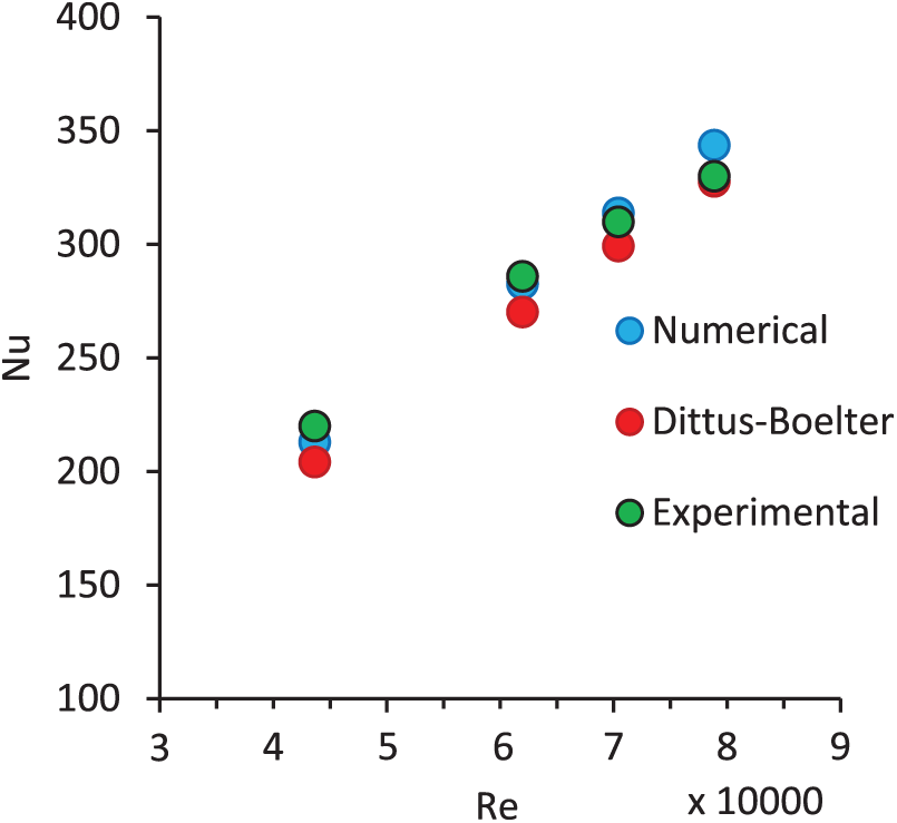
Figure 17: Average Nusselt number with Reynolds number for a circular fin receiver tube
The effects of triangular fins for

Figure 18: Average Nusselt number with Reynolds number for a triangular fin receiver tube
The temperature boundary at the tube exit considering tubes with plain, square, circular, and triangular fins is highlighted in Fig. 19a. It may be observed that the temperature distribution with uniform flux is determined to be inconsistent, having a hot area around the heated side, and a cold area around the unheated side. The peak temperature of the outer surface is observed to be 340 K. As depicted in Fig. 19b, the temperature boundary for fluid areas shows that tube with triangular fins has the least water temperature around the heated side as compared to the tubes with square or circular fins. Clearly, heat transfer is enhanced more with the use of triangular fins having low thermal resistance and boundary layer thickness. The maximum water temperature at the heated side is 316 K considering a circular fin, which is 2% higher compared to the triangular fin.

Figure 19: Temperature contours with plain, circular, square, and triangular fins, where e = 6 mm and
The temperature gradient at the outlet of the receiver gives a clear idea regarding the thermal stress characteristics for each shape. With a decrease in Reynolds number, there is a decrease in the difference between the maximum and minimum temperatures, which is because of the low-speed flow that allows water to absorb more heat through an increase in residence time. Fig. 20 highlights the temperature gradients for smooth, square finned, circular finned, and triangular finned tubes, respectively. In the planed tube, there is a 7% drop in the temperature gradient between the hot tube and water, thereby causing increased thermal stress on the absorber tube. Nevertheless, the addition of the fins provides for gradual temperature decrease, corresponding to decreased thermal stress and better receiver lifetime.

Figure 20: Variation of temperature gradient on tube’s exit for smooth tube, tube with square fins, circular fin, and triangular fin vs. Reynolds number. (a) Smooth tube, (b) square fin, (c) circle fin, (d) triangle fin
In the current work, a novel solar tower receiver design is proposed and evaluated experimentally and numerically using distinct fins having a uniform effect of heat flux on the external receiver and water being the heat transfer fluid. Changes in Nusselt number and different Reynolds number for every observation were recorded. The Reynolds number ranged between 28,000 and 78,000. Using the results, it may be concluded that.
The friction coefficient values concerning water flow show a slight decrease with a corresponding increase in Reynolds number. Moreover, the friction coefficient also increases with the addition of internal longitudinal fins. With a decrease in hydraulic diameter, the friction factor increases; hence, the highest value is determined in the case of circular fins, while it is lowest for triangular fins.
The pressure drop is in direct proportion to the Reynolds number while in inverse proportion with the hydraulic diameter. higher by 3.5% and 7.5%, sequentially, compared to circular and square tube fins.
Nusselt number increases with a corresponding increase in Reynolds number. Moreover, it increases when internal fins are added. Triangular fins provide for maximum thermal transfer enhancement since it corresponds to the maximum Nu. Nu is higher by 3.5% to 7.5%, compared to circular and square tube fins.
Insertion of fins causes the temperature gradient to decrease gradually, thereby causing less thermal stress and increasing receiver lifetime.
The Dittus–Boelter correlation may still be applied for the calculation of heat transfer in an absorber tube having uniform heat flux.
The solar tower receiver may be enhanced with several changes being introduced. Moreover, other studies may explore further on this topic.
Funding Statement: The authors received no specific funding for this study.
Conflicts of Interest: The authors declare that they have no conflicts of interest to report regarding the present study.
1. H. Shatnawi, C. W. Lim and F. B. Ismail, “Solar thermal power: Appraisal of solar power towers,” in MATEC Web Conf., Malaysia, vol. 225, pp. 1–6, 2018. [Google Scholar]
2. J. M. Lata, M. Rodríguez and M. Á. de Lara, “High flux central receivers of molten salts for the new generation of commercial stand-alone solar power plants,” Journal of Solar Energy Engineering, vol. 130, no. 2, pp. 21002, 2008. [Google Scholar]
3. L. Marocco, G. Cammi, J. Flesch and T. Wetzel, “Numerical analysis of a solar tower receiver tube operated with liquid metals,” International Journal of Thermal Sciences, vol. 105, no. 7, pp. 22–35, 2016. [Google Scholar]
4. G. Zhu and C. Libby, “Review and future perspective of central receiver design and performance,” in AIP Conf. Proc., June, Abu Dhabi, UAE, vol. 1850, no. 1, pp. 30052, 2017. [Google Scholar]
5. K. Nandakumar and J. H. Masliyah, “Fully developed viscous flow in internally finned tubes,” Chemical Engineering Journal, vol. 10, no. 1, pp. 113–120, 1975. [Google Scholar]
6. V. M. Maytorena and J. F. Hinojosa, “Three-dimensional numerical study of direct steam generation in vertical tubes receiving concentrated solar radiation,” International Journal of Heat and Mass Transfer, vol. 137, pp. 413–433, 2019. [Google Scholar]
7. A. Piña-Ortiz, J. F. Hinojosa, R. A. Pérez-Enciso, V. M. Maytorena, R. A. Calleja et al., “Thermal analysis of a finned receiver for a central tower solar system,” Renewable Energy, vol. 131, no. 57, pp. 1002–1012, 2019. [Google Scholar]
8. C. Chang, X. Li and Q. Q. Zhang, “Experimental and numerical study of the heat transfer characteristics in solar thermal absorber tubes with circumferentially non-uniform heat flux,” Energy Procedia, vol. 49, pp. 305–313, 2014. [Google Scholar]
9. R. López-Martín and L. Valenzuela, “Optical efficiency measurement of solar receiver tubes: A testbed and case studies,” Case Studies in Thermal Engineering, vol. 12, no. June, pp. 414–422, 2018. [Google Scholar]
10. Q. Yu, Z. Wang and E. Xu, “Simulation and experimental research of 1MWe solar tower power plant in China,” in AIP Conf. Proc., May, Cape Town, South Africa, vol. 1734, no. 1, pp. 70032, 2016. [Google Scholar]
11. B. Amina, A. Miloud, L. Samir, B. Abdelylah and J. P. Solano, “Heat transfer enhancement in a parabolic trough solar receiver using longitudinal fins and nanofluids,” Journal of Thermal Science, vol. 25, no. 5, pp. 410–417, 2016. [Google Scholar]
12. X. Gong, F. Wang, H. Wang, J. Tan, Q. Lai et al., “Heat transfer enhancement analysis of tube receiver for parabolic trough solar collector with pin fin arrays inserting,” Solar Energy, vol. 144, no. 10, pp. 185–202, 2017. [Google Scholar]
13. Z. Liu, Y. Yue, L. She and G. Fan, “Numerical analysis of turbulent flow and heat transfer in internally finned tubes,” Frontiers in Energy Research, vol. 7, no. July, pp. 1–12, 2019. [Google Scholar]
14. H. Shatnawi, C. Wai Lim, F. B. Ismail and A. Aldossary, “Numerical study of heat transfer enhancement in a solar tower power receiver, through the introduction of internal fins,” Journal of Advanced Research in Fluid Mechanics and Thermal Sciences, vol. 74, no. 1, pp. 98–118, 2020. [Google Scholar]
15. M. S. Baba, A. V. S. R. Raju and M. B. Rao, “Heat transfer enhancement and pressure drop of Fe3O4-water nanofluid in a double tube counter flow heat exchanger with internal longitudinal fins,” Case Studies in Thermal Engineering, vol. 12, no. August, pp. 600–607, 2018. [Google Scholar]
16. J. Gretz, A. S. Strub and A. Skinrood, “Thermo-Mechanical Solar Power Plants,” in Proc. of the Second Int. Workshop on the Design, Construction and Operation of Solar Central Receiver Projects, 4–8 June, 1984, vol. 2, Varese, Italy: Springer Science & Business Media, 2013. [Google Scholar]
17. C. E. Tyner, J. P. Sutherland and W. R. Gould Jr., Solar Two: A Molten Salt Power Tower Demonstration. Albuquerque, NM (United StatesSandia National Labs, 1995. [Google Scholar]
18. N. Balaban, Energy 2000: The Beginning of a New Millennium. Boca Raton, Florida, United States: CRC Press, 2000. [Google Scholar]
19. J. E. Pacheco, M. Ralph, J. Chavez, S. Dunkin, E. Rush et al., Results of Molten Salt Panel and Component Experiments for Solar Central Receivers: Cold Fill, Freeze/Thaw, Thermal Cycling and Shock, and Instrumentation Tests. Albuquerque, New Mexico, United States: Sandia National Laboratories, 1995. [Google Scholar]
20. M. Fares, M. AL-Mayyahi and M. AL-Saad, “Heat transfer analysis of a shell and tube heat exchanger operated with graphene nanofluids,” Case Studies in Thermal Engineering, vol. 18, no. October, pp. 100584, 2020. [Google Scholar]
21. O. S. Wesh, “Tube with internal fins and method of making same,” U.S. Patent No. 2,930,405, March, 1960. [Google Scholar]
22. H. T. Kim, B. W. Rhee and J. H. Park, “Benchmark calculations of a radiation heat transfer for a candu fuel channel analysis using the CFD Code,” Journal of Nuclear Science and Technology, vol. 43, no. 11, pp. 1422–1430, 2006. [Google Scholar]
23. M. Jaric, S. Genić, I. Arandjelović, P. Kolendić, M. Jarić et al., “A Review of explicit approximations of Colebrook’s equation,” FME Transactions, vol. 39, no. 2, pp. 39–67, 2011. [Google Scholar]
24. D. Taler and J. Taler, “Simple heat transfer correlations for turbulent tube flow,” in E3S Web of Conferences, Polanica-Zdrój, Poland, vol. 13, pp. 2008, 2017. [Google Scholar]
25. K. Ruengpayungsak, M. Kumar, V. Chuwattanakul and S. Eiamsa-ard, “Experimental study of the effects of inclusion of rectangular-cut twisted tapes on heat transfer and pressure drop in a round tube,” Arabian Journal for Science and Engineering, vol. 44, no. 12, pp. 10303–10312, 2019. [Google Scholar]
26. A. Ahmadian, M. Bilal, M. A. Khan and M. I. Asjad, “The non-Newtonian maxwell nanofluid flow between two parallel rotating disks under the effects of magnetic field,” Scientific Report, vol. 10, no. 1, pp. 1–14, 2020. [Google Scholar]
 | This work is licensed under a Creative Commons Attribution 4.0 International License, which permits unrestricted use, distribution, and reproduction in any medium, provided the original work is properly cited. |