DOI:10.32604/cmc.2021.016027
| Computers, Materials & Continua DOI:10.32604/cmc.2021.016027 | |
| Article |
Single-Layer Wideband Circularly Polarized Antenna Using Non-Uniform Metasurface for C-band Applications
1Faculty of Electrical and Electronic Engineering, PHENIKAA University, Hanoi, 12116, Vietnam
2PHENIKAA Research and Technology Institute (PRATI), A&A Green Phoenix Group JSC, Cau Giay, 11313, Hanoi, Vietnam
3Department of Computer and Communication Engineering, Chungbuk National University, Cheongju 28644, Korea
*Corresponding Author: Khoa Nguyen-Dang. Email: khoa.nguyendang@phenikaa-uni.edu.vn
Received: 19 December 2020; Accepted: 29 January 2021
Abstract: A single-layer design of non-uniform metasurface (MS) based circularly polarized (CP) antenna with wideband operation characteristic is proposed and investigated in this paper. The antenna is excited by a truncated corner squared patch as a primary radiating CP source. Then, a non-uniform MS is placed in the same layer with the driven patch. Besides increasing the impedance bandwidth, the non-uniform MS also generates two additional CP bands in the high frequency band, leading to significantly increase the antenna’s overall performances. The use of non-uniform MS distinguishes our design from the other CP MS based antennas in literature, in which the MS is formed by multiple uniform unit cells and placed in different layer with the radiating element. For validation, an antenna prototype, whose overall dimensions of 0.94
Keywords: Circular polarization; metasurface; non-uniform; patch antenna; wideband
The use of circularly polarized (CP) antenna has been illustrated as a useful method for multipath interferences reduction as well as polarization mismatch mitigation. The antennas with simple design, low profile as well as wideband operation characteristics have received lots of attention from researchers. Single-fed patch antennas are considered as a potential candidate to satisfy the abovementioned requirements. However, an inherently narrow operating bandwidth (BW) caused by the high quality factor is a critical drawback of this antenna type [1]. Up to now, the task for BW enhancement of the single-fed CP patch antenna while maintaining low profile feature is still very challenging. The most common method is to employ a low permittivity substrate, which is constructed with an air gap between a ground plane and a radiating element [2–9]. This method can significantly increase the BW up to approximately 24% [9]. However, the antenna’s profile is typically higher than 0.1
In this paper, a low-profile MS based CP antenna with single layer and wideband operation characteristics is proposed for the C-band applications (4–8 GHz) [23]. It is noted that unlike the conventional CP MS antennas [12–19], where the MS is comprised of multiple uniform unit cells and positioned in different layer with the radiating source, this paper takes a different approach. Here, the MS is formed by non-uniform unit cells and designed in the same layer with the driven patch. The proposed MS is able to generate additional resonances, which are then combined with the original one from the driven patch to achieve wide operating BW. The proposed design is an extension of the work in [20], but with significant BW enhancement of about 40%. Besides, the use of non-uniform MS to improve the performance of CP antenna has not been presented in literature. These are the main contributions of our paper. The proposed design is first characterized in full-wave simulation tool High-Frequency Structure Simulator (HFSS) and then validated by measurements.
To have wideband operation, the driven patch and the MS are designed so that their operating bands are closed to each other. The square patch with corner truncation will work at the lowest band. Its dimension (Wp) for operation at the fundamental TM11 mode (fr) can be approximately defined by:
where c is the speed of light,
where,
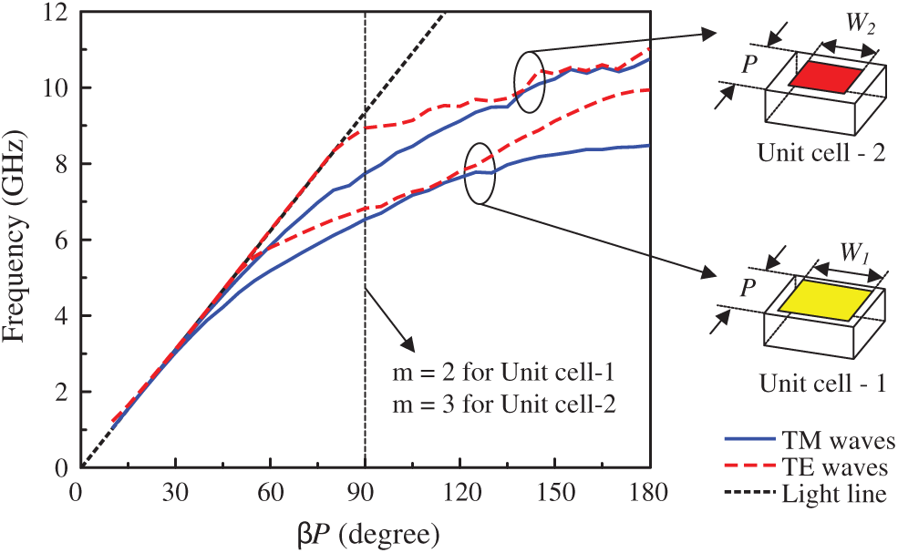
Figure 1: Dispersion diagram of different unit cells. The parameters are as follows: P = 8 mm, W1 = 7.5 mm, W2 = 5 mm
3.1 Antenna with Uniform Metasurface
The geometrical configuration of the wideband CP antenna with uniform MS is illustrated in Fig. 2. The antenna is constructed with a driven microstrip patch, a MS and a ground plane. The antenna is fabricated on a single layer of a Taconic RF-35 substrate (permittivity of
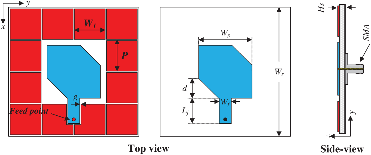
Figure 2: Geometry of the single-layer CP antenna with uniform MS
The previous studies [12–19] design the MS on a different layer from the driven element, which increases the design complexity and cost. In this paper, all of the radiating components are printed in the same layer. The evolution to achieve the final design is presented in Fig. 3. In the first stage, antenna without MS as Antenna-1 is considered. Then, the patch is embedded into the center of the
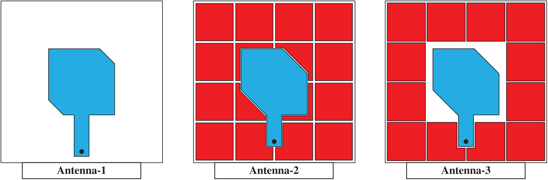
Figure 3: Design evolution of the final design
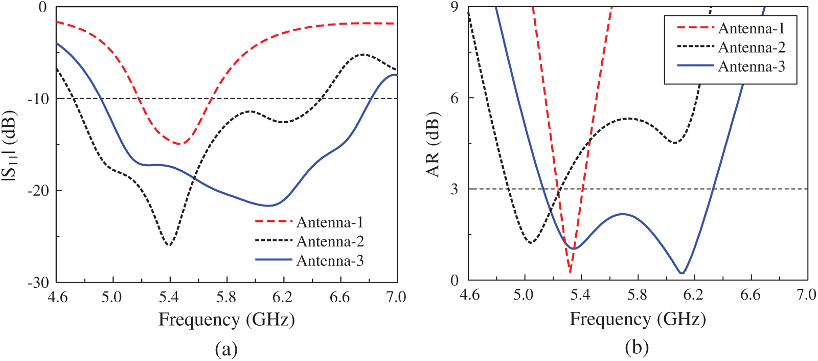
Figure 4: Simulated performances of different antenna configurations. (a) |S11|, (b) AR
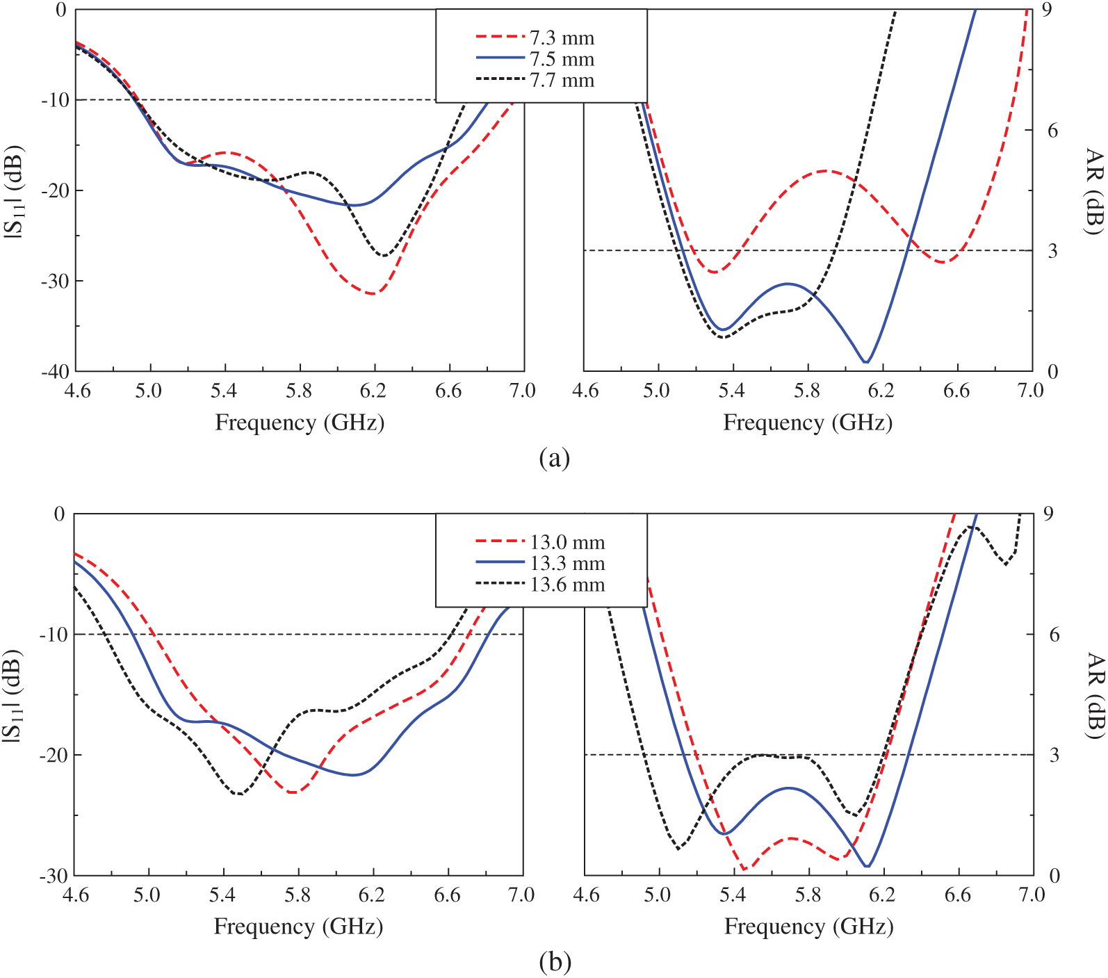
Figure 5: Simulated |S11| and AR of Antenna-3 for different values of (a) W1 and (b) Wp
3.2 Antenna with Non-Uniform Metasurface
Based on the abovementioned design, additional array of MS is inserted as Antenna-4 depicted in Fig. 6. Similar to the previous MS, all the center unit cells of the additional
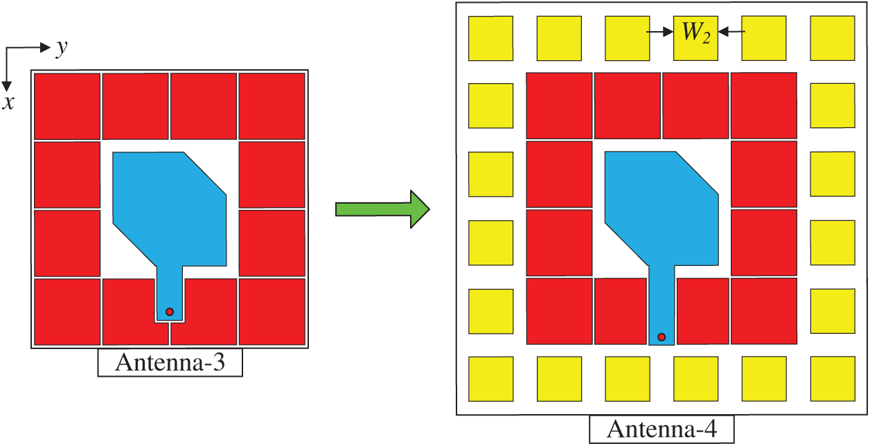
Figure 6: Geometry of the antenna with non-uniform MS
The simulated performances of the antenna with uniform MS and non-uniform MS are illustrated in Fig. 7. It can be seen that by using non-uniform MS, an additional |S11| resonance at 7.1 GHz is generated for Antenna-4. Thus, the impedance BW of the antenna increases from 32.4% (4.92–6.82 GHz) to 42.9% (4.84–7.48 GHz). Besides, another CP band at 6.5 GHz is also realized and the overall 3 dB AR BW improves from 21% (5.12–6.32 GHz) to 26.6% (5.08–6.64 GHz). In fact, the additional |S11| and CP bands can be adjusted by tuning the size of the outer MS unit cell, W2. Fig. 8 shows the |S11| and AR for different values of W2. Obviously, tuning W2 only has significant influence on the highest |S11| and CP bands, which increase as W2 decreases. Meanwhile, the lower operating bands are almost stable with the variation of W2. In terms of broadside gain, Antenna-3 observes a significant drop in the high frequency region of greater than 6.2 GHz. For Antenna-4 with additional MS, the gain is increased in higher band and the gain is better than 6 dBi over very wide frequency range from 4.6 to 7.4 GHz.
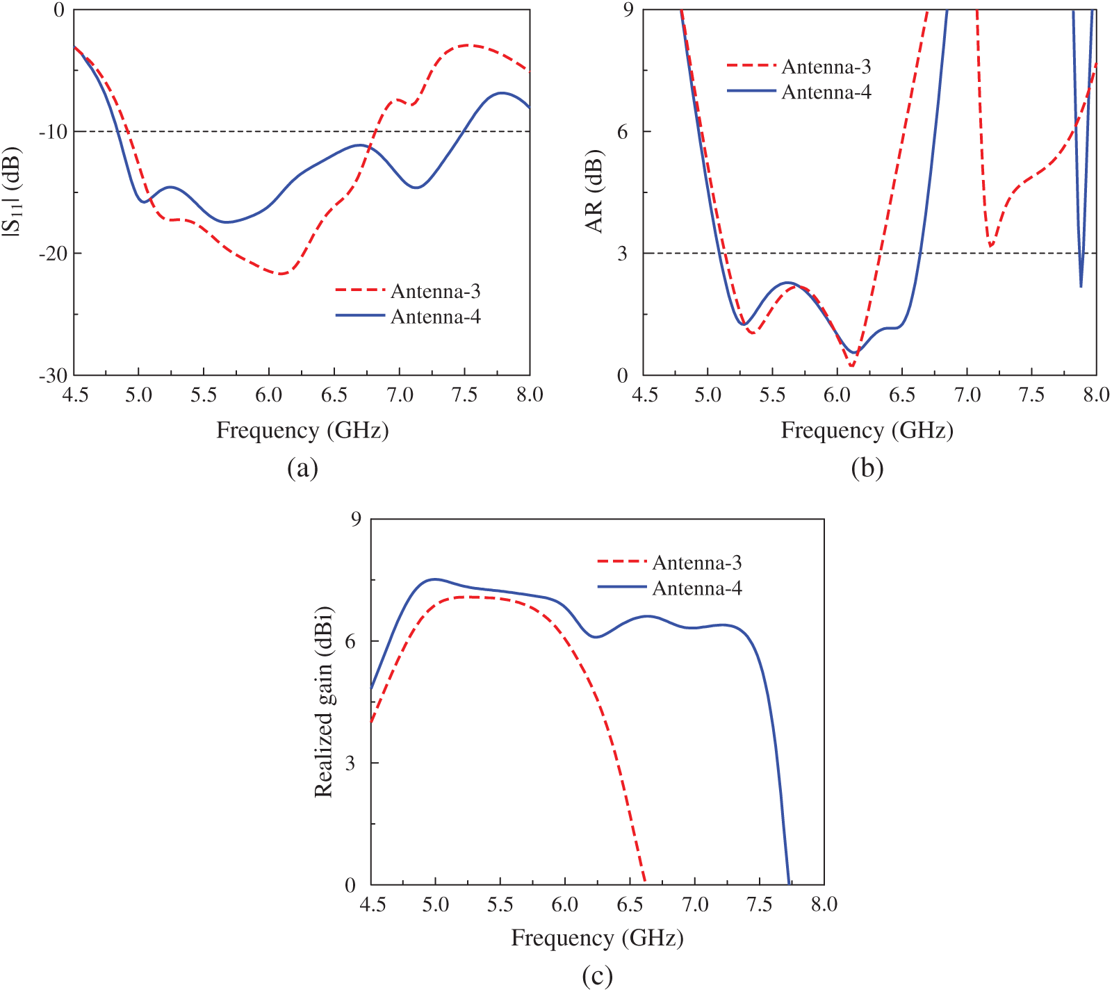
Figure 7: Simulated (a) |S11|, (b) AR, and (c) gain of the antenna with uniform MS and non-uniform MS
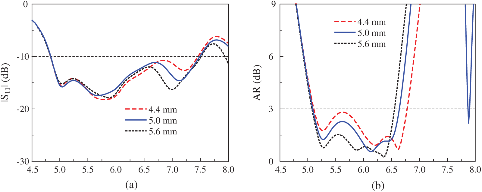
Figure 8: Simulated (a) |S11| and (b) AR of Antenna-4 with different values of W2
In order to optimize this antenna, the feeding line is very important parameter to the matching performance, which is demonstrated in Fig. 9. The simulated data indicates that increasing Lf results in better impedance matching. However, when Lf is larger than 18 mm, the matching is degraded.
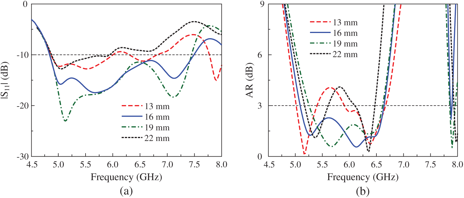
Figure 9: Simulated (a) |S11| and (b) AR results of Antenna-4 with different values of Lf
The proposed wideband CP antenna using non-uniform MS was fabricated using etching technique as shown in Fig. 10. The antenna’s reflection coefficient was measured using the PNA Network Analyzer N5224A and the far-field characteristics were implemented in an anechoic chamber by Microwave Technologies Group [25]. The chamber is fully installed with electrically-thick foam absorber and two horn antennas are employed as reference antennas. The testing antenna is mounted on a computer-controlled rotating positioner. Generally, the measured data is well matched with the simulated one. It still exists several discrepancies due to the tolerance in fabrication and imperfection in measurement setup.
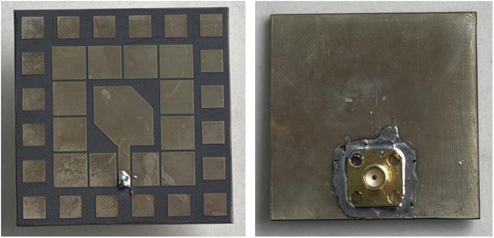
Figure 10: Photograph of fabricated antenna
The simulated and tested |S11| results of the proposed antenna are presented in Fig. 11a. The antenna shows good impedance matching in a wide frequency band from 4.9 to 7.4 GHz, equivalent to 40.7%. Fig. 11b depicts the far-field radiation characteristics in terms of AR and realized gain in broadside direction. As observed, the measured 3 dB AR BW is 27.1%, ranging from 5.1 to 6.7 GHz, and along with this, the measured gain is from 5.7 to 7.2 dBic. Fig. 12 plots the antenna gain radiation patterns in two principal (x-z and y-z planes) at different operating frequencies. As observed, the right-hand CP (RHCP) is the dominant r mode over the left-hand CP (LHCP). At the broadside direction (
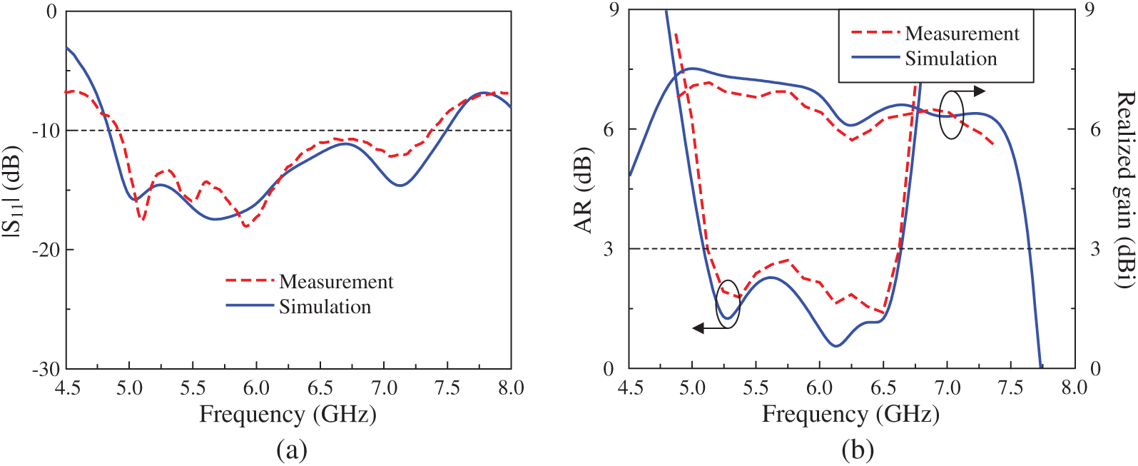
Figure 11: Simulated and measured (a) |S11| and (b) AR and gain of the proposed antenna
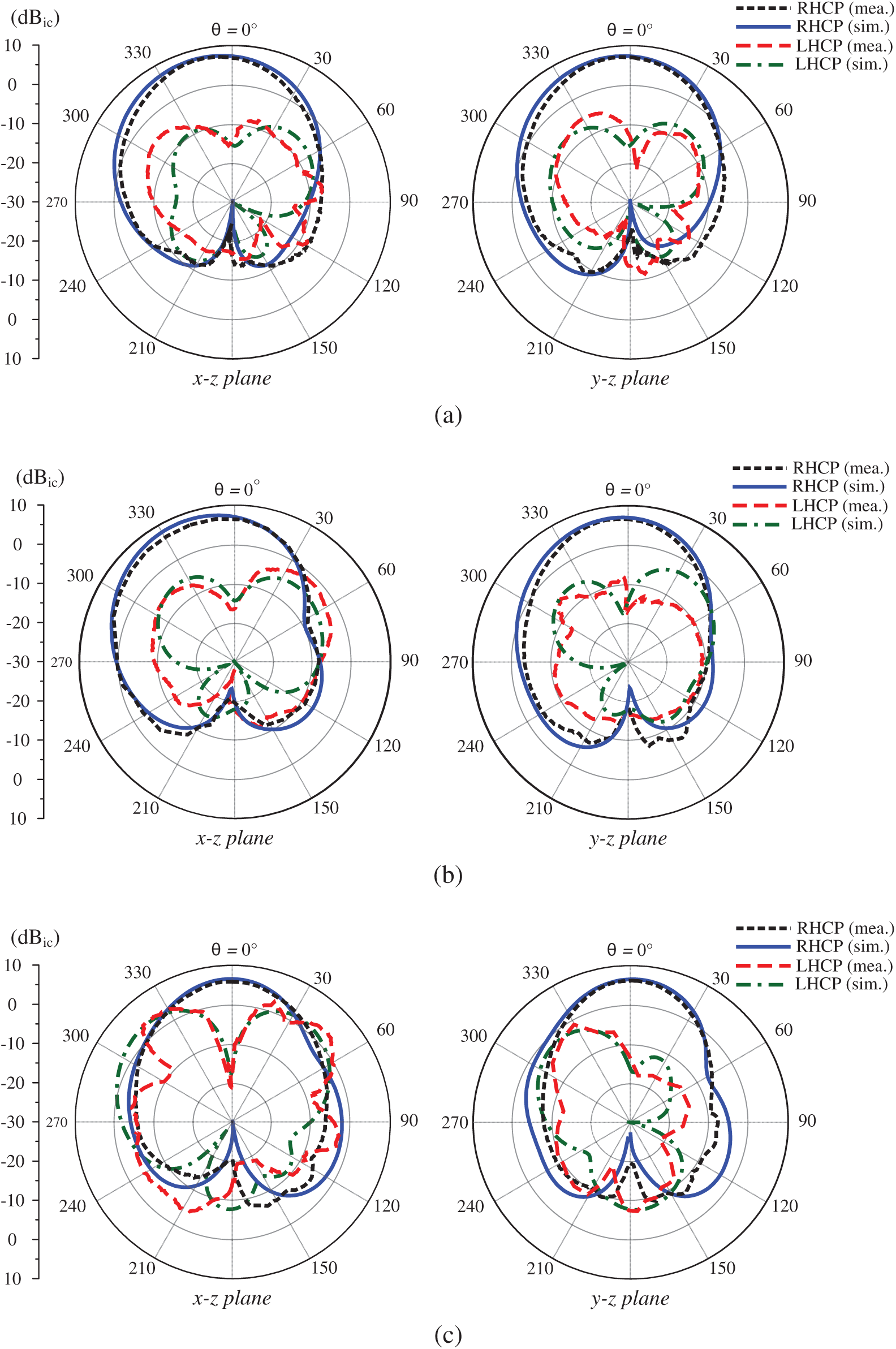
Figure 12: Simulated and measured gain radiation patterns of the proposed antenna. (a) 5.3 GHz, (b) 5.9 GHz, (c) 6.5 GHz
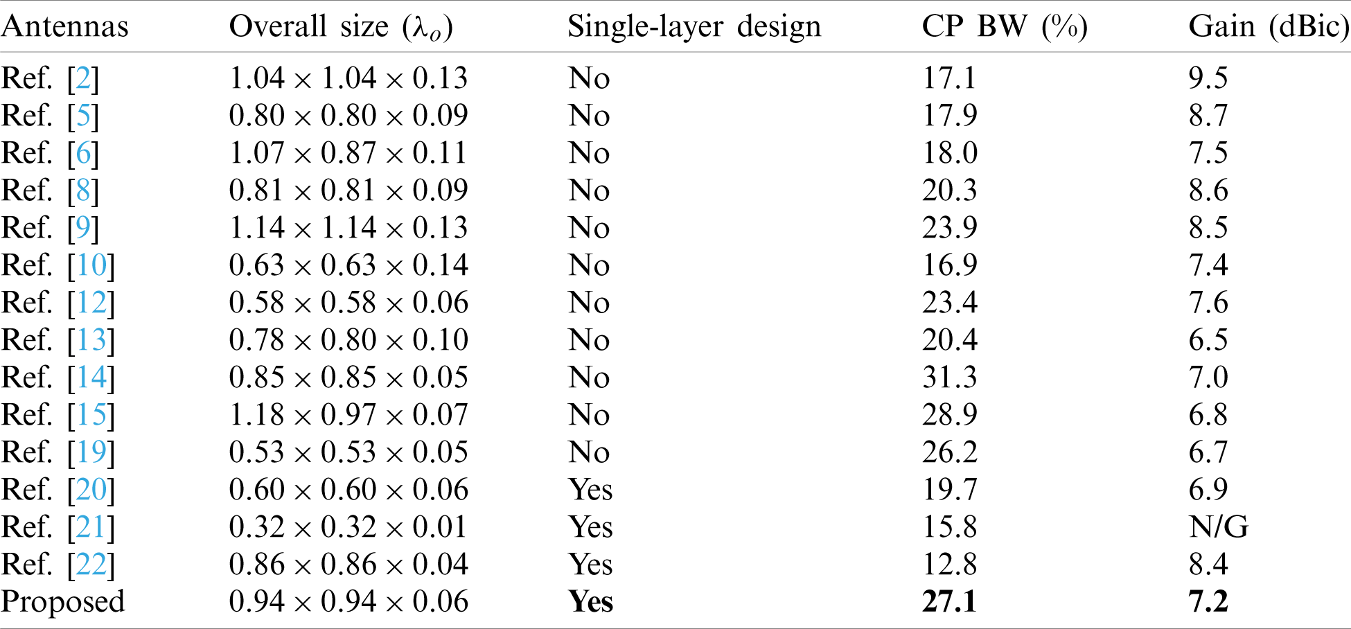
The performance comparison among the low-profile, wideband CP antennas is tabulated in Tab. 1. As seen, the presented antenna shows the best operating BW among the single-layer designs [20–22]. Besides, the presented work has wider BW than most of other multi-layer ones. Although the designs in [14,15] have wider operating BW, their structures are more complicated than that of the proposed design.
Table 1: Performance comparison among the low-profile, single-fed, wideband CP antennas
A single-layer MS based wideband CP antenna has been presented and investigated in this paper. This paper utilizes a non-nuniform MS, which has potential to not only increase the impedance BW but also produce two additional CP bands to significantly widen the overall 3-dB AR BW of the proposed design. The measurements implemented on a fabricated antenna demonstrate that wide operating BW of 27.1% (5.1–6.7 GHz) is attained. Additionally, the antenna also exhibits good radiation characteristics and gain in broadside direction of better than 5.7 dBic. The proposed antenna can be a potential candidate for communication systems in C-band, such as wireless local area network (WLAN), satellite, cordless telephones and so on.
Funding Statement: The authors received no specific funding for this study.
Conflicts of Interest: The authors declare that they have no conflicts of interest to report regarding the present study.
1. P. C. Sharma and K. C. Gupta, “Analysis and optimized design of single feed circularly polarized microstrip antennas,” IEEE Transactions on Antennas and Propagation, vol. 31, no. 6, pp. 949–955, 1983. [Google Scholar]
2. J. Wu, W. Hu, Y. Yin and R. Lian, “Broadband circularly polarized antennas with center-slot-feeding,” Microwave and Optical Technology Letters, vol. 57, no. 12, pp. 2793–2797, 2015. [Google Scholar]
3. N. Hussain, M. Jeong, J. Park and N. Kim, “A broadband circularly polarized Fabry-Perot resonant antenna using a single-layered PRS for 5G MIMO applications,” IEEE Access, vol. 7, pp. 42897–42907, 2019. [Google Scholar]
4. D. A. Sehrai, F. Muhammad, S. H. Kiani, Z. H. Abbas, M. Tufail et al., “Gain-enhanced metamaterial based antenna for 5G communication standards,” Computers, Materials & Continua, vol. 64, no. 3, pp. 1587–1599, 2020. [Google Scholar]
5. J. Wu, X. Ren, Z. Wang and Y. Yin, “Broadband circularly polarized antenna with L-shaped strip feeding and shorting-pin loading,” IEEE Antennas and Wireless Propagation Letters, vol. 13, pp. 1733–1736, 2014. [Google Scholar]
6. T. Mondal, S. Maity, R. Ghatak and S. R. B. Chaudhuri, “Design and analysis of a wideband circularly polarized perturbed psi-shaped antenna,” IET Microwaves, Antennas & Propagation, vol. 12, no. 9, pp. 1582–1586, 2018. [Google Scholar]
7. J. Li, H. Liu, S. Zhang, M. Luo, Y. Zhang et al., “A wideband single-fed, circularly-polarized patch antenna with enhanced axial ratio bandwidth for UHF RFID reader applications,” IEEE Access, vol. 6, pp. 55883–55892, 2018. [Google Scholar]
8. W. Yang, J. Zhou, Z. Yu and L. Li, “Single-fed low profile broadband circularly polarized stacked patch antenna,” IEEE Transactions on Antennas and Propagation, vol. 62, no. 10, pp. 5406–5410, 2014. [Google Scholar]
9. J. Wu, Y. Yin, Z. Wang and R. Lian, “Broadband circularly polarized patch antenna with parasitic strips,” IEEE Antennas and Wireless Propagation Letters, vol. 14, pp. 559–562, 2015. [Google Scholar]
10. Q. W. Lin, H. Wong, X. Y. Zhang and H. W. Lai, “Printed meandering probe-fed circularly polarized patch antenna with wide bandwidth,” IEEE Antennas and Wireless Propagation Letters, vol. 13, pp. 654–657, 2014. [Google Scholar]
11. H. Wong, Q. W. Lin, H. W. Lai and X. Y. Zhang, “Substrate integrated meandering probe-fed patch antennas for wideband wireless devices,” IEEE Transactions on Components, Packaging and Manufacturing Technology, vol. 5, no. 3, pp. 381–388, 2015. [Google Scholar]
12. S. X. Ta and I. Park, “Low-profile broadband circularly polarized patch antenna using metasurface,” IEEE Transactions on Antennas and Propagation, vol. 63, no. 12, pp. 5929–2934, 2015. [Google Scholar]
13. T. Nakamura and T. Fukusako, “Broadband design of circularly polarized microstrip patch antenna using artificial ground structure with rectangular unit cells,” IEEE Transactions on Antennas and Propagation, vol. 59, no. 6, pp. 2103–2110, 2011. [Google Scholar]
14. S. Liu, D. Yang and J. Pan, “Wideband circularly polarized patch antennas on reactive impedance substrates,” IEEE Antennas and Wireless Propagation Letters, vol. 18, no. 7, pp. 1395–1399, 2019. [Google Scholar]
15. S. S. Jash, C. Goswami and R. Ghatak, “A low profile broadband circularly polarized planar antenna with an embedded slot realized on a reactive impedance surface,” AEU-International Journal of Electronics and Communications, vol. 108, no. 1, pp. 62–72, 2019. [Google Scholar]
16. C. Zhao and C. F. Wang, “Characteristic mode design of wide band circularly polarized patch antenna consisting of H-shaped unit cells,” IEEE Access, vol. 6, pp. 25292–25299, 2018. [Google Scholar]
17. S. Liu, D. Yang and J. Pan, “A low-profile circularly polarized metasurface antenna with wide axial-ratio beamwidth,” IEEE Antennas and Wireless Propagation Letters, vol. 18, no. 7, pp. 1438–1442, 2019. [Google Scholar]
18. Y. Juan, W. Yang and W. Che, “Miniaturized low-profile circularly polarized metasurface antenna using capacitive loading,” IEEE Transactions on Antennas and Propagation, vol. 67, no. 5, pp. 3527–3532, 2019. [Google Scholar]
19. Q. Chen and H. Zhang, “Dual-patch polarization conversion metasurface-based wideband circular polarization slot antenna,” IEEE Access, vol. 6, pp. 74772–74777, 2018. [Google Scholar]
20. H. H. Tran, N. Hussain and T. T. Le, “Single-layer low-profile wideband circularly polarized patch antenna surrounded by periodic metallic plates,” International Journal of RF and Microwave Computer-Aided Engineering, vol. 29, no. 12, pp. e21969, 2019. [Google Scholar]
21. Z. L. Yang, L. Zhu and S. Xiao, “An implantable wideband circularly polarized microstrip patch antenna via two pairs of degenerate modes,” IEEE Access, vol. 7, pp. 4239–4247, 2019. [Google Scholar]
22. Z. Liang, J. Ouyang and F. F.Yang, “Low-profile wideband circularly polarized single-layer metasurface antenna,” Electronics Letters, vol. 54, no. 24, pp. 1362–1364, 2018. [Google Scholar]
23. Accessed Dec. 28, 2020, [Online]. Available: https://en.wikipedia.org/wiki/C_band_(IEEE). [Google Scholar]
24. F. Costa, O. Luukkonen, C. R. Simovski, A. Monorchio, S. A. Tretyakov et al., “TE surface wave resonances on high-impedance surface based antennas: Analysis and modeling,” IEEE Transactions on Antennas and Propagation, vol. 59, no. 10, pp. 3588–3596, 2011. [Google Scholar]
25. Accessed May 15, 2020, [Online]. Available: http://www.mtginc.co.kr. [Google Scholar]
 | This work is licensed under a Creative Commons Attribution 4.0 International License, which permits unrestricted use, distribution, and reproduction in any medium, provided the original work is properly cited. |