DOI:10.32604/cmc.2021.014606
| Computers, Materials & Continua DOI:10.32604/cmc.2021.014606 | |
| Article |
Low Area PRESENT Cryptography in FPGA Using TRNG-PRNG Key Generation
1Department of Electronic and Communication Engineering, Muthayammal Engineering College, Rasipuram, Namakkal, Tamilnadu, India
2Department of Electronics and Communication Engineering, SRM TRP Engineering College, Tiruchirappalli, Tamilnadu, India
3Department of Telecommunication Engineering, GSSS Institute of Engineering and Technology for Women, Mysuru, India
4Faculty of Information Technology, Graduate School, Duy Tan University, Da Nang, 550000, Viet Nam
5Department of Information and Communication Technology, School of Electrical and Computer Engineering, Xiamen University Malaysia, Sepang, 43900, Malaysia
*Corresponding Author: Raja Majid Mehmood. Email: rmeex07@ieee.org, rajamajid@xmu.edu.my
Received: 29 September 2020; Accepted: 31 October 2020
Abstract: Lightweight Cryptography (LWC) is widely used to provide integrity, secrecy and authentication for the sensitive applications. However, the LWC is vulnerable to various constraints such as high-power consumption, time consumption, and hardware utilization and susceptible to the malicious attackers. In order to overcome this, a lightweight block cipher namely PRESENT architecture is proposed to provide the security against malicious attacks. The True Random Number Generator-Pseudo Random Number Generator (TRNG-PRNG) based key generation is proposed to generate the unpredictable keys, being highly difficult to predict by the hackers. Moreover, the hardware utilization of PRESENT architecture is optimized using the Dual port Read Only Memory (DROM). The proposed PRESENT-TRNG-PRNG architecture supports the 64-bit input with 80-bit of key value. The performance of the PRESENT-TRNG-PRNG architecture is evaluated by means of number of slice registers, flip flops, number of slices Look Up Table (LUT), number of logical elements, slices, bonded input/output block (IOB), frequency, power and delay. The input retrieval performances analyzed in this PRESENT-TRNG-PRNG architecture are Peak Signal to Noise Ratio (PSNR), Structural Similarity Index (SSIM) and Mean-Square Error (MSE). The PRESENT-TRNG-PRNG architecture is compared with three different existing PRESENT architectures such as PRESENT On-The-Fly (PERSENT-OTF), PRESENT Self-Test Structure (PRESENT-STS) and PRESENT-Round Keys (PRESENT-RK). The operating frequency of the PRESENT-TRNG-PRNG is 612.208 MHz for Virtex 5, which is high as compared to the PRESENT-RK.
Keywords: Dual port read only memory; hardware utilization; lightweight cryptography; malicious attackers; present block cipher; pseudo random number generator; true random number generator
Lightweight Cryptography (LWC) plays a vital role to obtain the higher security with low energy and low area in different sensitive applications such as implantable and wearable medical devices, radio-frequency identification tags, Wireless Nano sensors, and smart cards and secure embedded systems [1–3]. The symmetric cryptography is divided into two types such as block and stream ciphers. The block cipher processes the one input block at a time and produces the output block for each input block, but the stream cipher frequently processes the input elements and generates the one output element at a time [4,5]. FPGA is considered as a growing design platform to implement the cryptographic algorithms because of its in-house security and reconfigurability [6].
Generally, the Advanced Encryption Standard (AES) is widespread block cipher and fundamental for many security systems [7]. But AES used in the high-performance processors is not suitable in resource-constrained platforms because of its inadequate area and energy/power [8]. Therefore, the better tradeoff between the security, power, area and speed is obtained by designing the lightweight block cipher [9]. Some of the examples of the lightweight ciphers are the STES [10], SEED [11], ANU [12], KLEIN [13], PRESENT [14], and KASUMI [15] and so on. From the different lightweight cipher, PRESENT block cipher is selected as an efficient algorithm due to its hardware efficiency and it also standardized by ISO/IEC 29192-2. However, the hardware failures are considered as the natural fault in the implementation of Very-Large-Scale Integration (VLSI). This natural fault increases the sensitivity and creates the malicious attacks over the cryptographic hardware and embedded systems [16]. The conventional LWC method uses the same type of generators and identical keys to accomplish both the encryption and decryption process that leads susceptible to the attacks [17].
The major contributions of this research paper are given as follows:
• The PRESENT architecture improves the robustness against the malicious attackers by random key generation using TRNG-PRNG module and two stage security is used during the encryption process.
• In PRESENT architecture, the key value from the TRNG-PRNG module is generated for each clock and plaintext. Therefore, the identification of key value by the unauthenticated users (i.e., malicious attackers) is difficult during the encryption/decryption process.
• A DROM is utilized to minimize the number of logical elements used in the PRESENT architecture. The DROM used in the PRESENT architecture accomplishes the operation of Substitution box (S-box).
The overall organization of the paper is: The literature survey related to existing PRESENT architecture is described in Section 2. The problem statement found from the literature survey along with solution is described in Section 3. Section 4 describes the PRESENT architecture by using key scheduling approach and TRNG-PRNG module. The results and discussion of the PRESENT-TRNG-PRNG architecture is presented in Section 5. Finally, the conclusion is made in Section 6.
The literature survey regarding the recent PRESENT block cipher is described along its advantages and limitations in this section.
Pandey et al. [18] implemented the PRESENT lightweight block cipher algorithm to accomplish the encryption and decryption processes. The developed PRESENT architecture processed 64-bit input value along with the 80/128 bit of key length. Additionally, the dynamic keys were provided with the OTF architecture to compute the intermediate key. Next, the generated intermediate keys were used to accomplish the encryption/decryption operation. The iterative method considered in the decryption is used to achieve the better tradeoff among time and area. The total power consumption of the PRESENT architecture was high at low frequency, when processed with high number of key bits (128 bit).
De Cnudde et al. [19] developed the evaluation of PRESENT block cipher under two different physical attacks such as Side-Channel Analysis (SCA) and fault attacks (FAs). The first order implementation was used to provide the security against the side-channel. Next, the Private Circuits II is used to provide the security against the FA. The leakage detection test was used to analyze the side channel evaluation. But, the Private Circuits II used for FA resistance in the PRESENT block cipher was expensive.
Azari et al. [20] implemented the PRESENT Cipher model that incorporated both encryption and decryption process. The encryption and decryption process were accomplished by using 80/128-bit key to obtain the security for 64-bit input value. The plain text of 64 bits processing requires 16 cycles to load the data during encryption process. Here, the PRESENT cipher obtains a higher throughput based on the effective encryption and decryption process. However, the PRESENT cipher used high number of S-boxes which increased the hardware utilization.
Rashidi [21] presented the two different low-cost and high-throughput block ciphers such as HIGHT and PRESENT to improve the security. Since, the modulo 28 was one of the complex blocks in the HIGHT algorithm. Next, the parallel prefix adders such as Sklansky, Han–Carlson, Kogge–Stone and Ladner–Fischer were used to design the modular adder. Moreover, the PRESENT cipher was supported by two key lengths such as 80-bit and 128-bit. The Karnaugh mapping was used to reduce the amount of logic gates in the S-box and critical path delay. But, the computation time was high and throughput was less when the unroll factor is high in block ciphers.
Lara-Nino et al. [22] developed the standardized lightweight cipher namely PRESENT to overcome the security issues caused at the extremely constrained environments. Moreover, the data in the registers were moved to the right that used to reduce the MUX size. The PRESENT architecture used two different alternatives to generate the RK of 80 bit and 128 bit. Since, the 80 bit and 128 bit input keys were generated using 20 bit registers and 32 bit registers respectively. The key given to the PRESENT architecture was manually generated by the key generator module and it can be easily predicted by hackers.
The problems obtained from the existing literature survey along with the solution by the PRESENT-TRNG-PRNG architecture is as follows.
The STS based PRESENT architecture requires an additional comparator to generate the output [19]. Next, the conventional PRESENT architecture uses high amount of S-box operation to accomplish the encryption process [20]. The unroll factor considered in the loop unrolling method also affects the performance of the hardware utilization [21]. The aforementioned constraints increase the number of logical elements used in the PRESENT architecture. Since, the increment of hardware utilization leads to affect the operating frequency and power of the overall PRESENT architecture. The manual key generation accomplished in the PRESENT architecture [22] generates the same key value for each clock cycle. The generation of same clock cycle for each round can be easily predicted by the malicious attackers.
Solution:
The logical components of PRESENT architecture are minimized by using the DROM. In this PRESENT architecture, 8 DROM is used instead of 16 S-boxes of the conventional PRESENT architecture. The DROM used in the PRESENT-TRNG-PRNG accomplishes the same process which is performed by the S-box. Moreover, the security of the PRESENT-TRNG-PRNG architecture is improved by using two different approaches: (1) two stage security approach and (2) unpredictable key generation using TRNG-PRNG module. The robustness of the PRESENT architecture is improved by generating the random key for each clock cycle and each plaintext.
4 PRESENT-TRNG-PRNG Architecture
In the PRESENT-TRNG-PRNG architecture, the logical elements are optimized by using the DROM to accomplish the encryption/decryption process. The PRESENT architecture is designed to support the 64-bit input value with 80-bit key length. Here, the random key generation is carried out by using the TRNG-PRNG module. The randomness of the key from the TRNG-PRNG module is improved using the two-stage security enabled during encryption process. The block diagram of the PRESENT-TRNG-PRNG architecture is shown in Fig. 1.
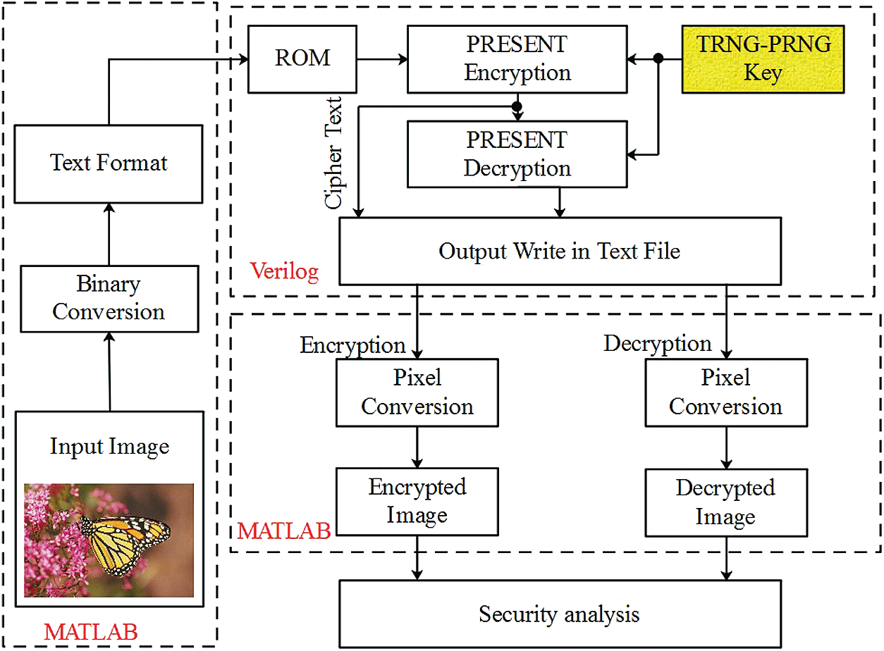
Figure 1: Block diagram of the PRESENT-TRNG-PRNG architecture
The overall working process of the PRESENT-TRNG-PRNG architecture are given as follows:
1. At first, the input image
2. Next, the binary value of the image pixels is written in the text format using MATLAB.
3. The TRNG-PRNG module is used to generate the random key value to accomplish the encryption operation. The decryption process is generally the inverse process of the encryption operation.
4. The Verilog (Modelsim) is used to process both the encryption/decryption process. Moreover, the output of encryption and decryption is written in the text format using the Verilog (Modelsim).
5. Then the text files are used in the MATLAB to convert the encrypted and decrypted binary value into the image.
The overall architecture of the path encryption for 64-bit data is shown in Fig. 2. At first, the one pixel from the image is converted into 8 bits and total plain text of 64-bit data
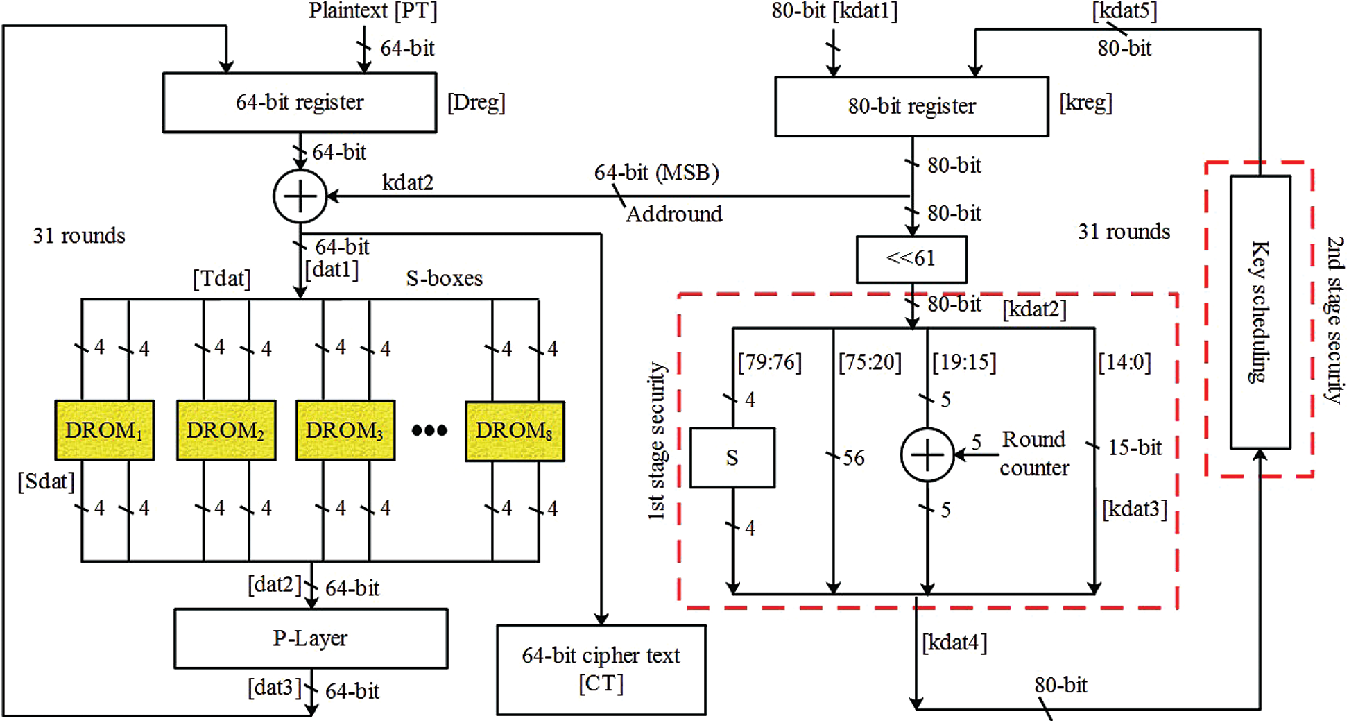
Figure 2: Architecture of 64-bit path encryption
The 80 bit of key value
where, the dat1 represents the XOR value between the plaintext and MSB of 64-bit data from the key value generated by TRNG-PRNG module.
Next, the XORed data is truncated into 16 four bit values which are shown in Eq. (2).
From the 16 sets of 4-bit values, each 2 sets of 4-bit values are given into the DROM which processes the operation of Substitution box (S-box). For example, the

The value obtained from the DROM is represented as Sdat which is obtained through the S-box operation. The value from the 8 DROMs are concatenated together and generated one 64-bit value i.e., dat2 which is shown in the Eq. (3).
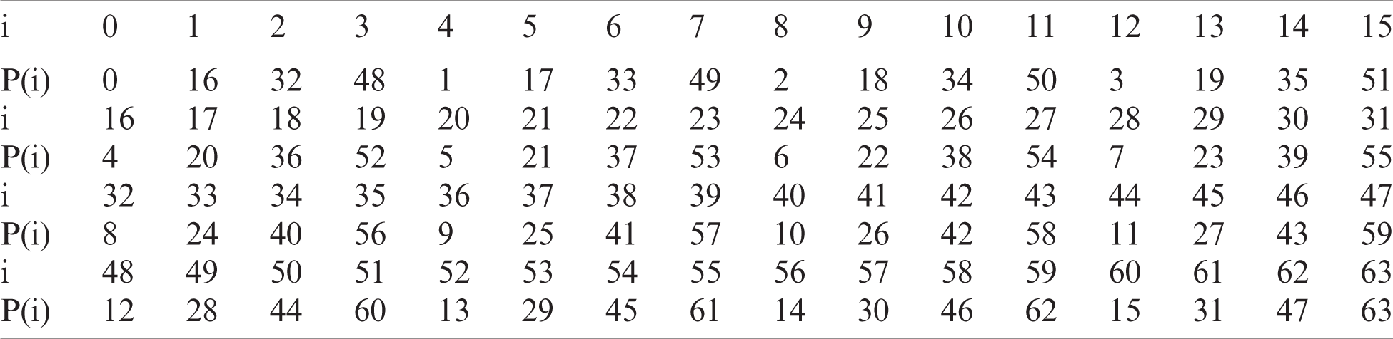
Then the concatenated 64-bit value is processed through the permutation layer (P-layer). This P-layer used to move the bit value in new bit position as shown in the Tab. 2. Moreover, the value from the P-layer is represented as dat3 and this updated dat3 is considered instead of plaintext for next 31 rounds.
On the other hand, the 80-bit key value of processed under the 61 left shift operation as shown in the Eq. (4).
Next, the kdat2 is divided into four sets such as
where, RC represents the round counter that varies from 0 to 31 for each round. The updated key values such as
This updated kdat4 is given to the key scheduling process to accomplish the second stage security. Both the first and second stage security are used to improve the randomness of the key values.
The architecture of key scheduling used in the 64-bit path encryption is shown in Fig. 3. This key scheduling is processed for the next 31 rounds to improve the security of the plaintext against malicious attackers. The 80 bit value of kdat4 is truncated into four 20 bit values such as
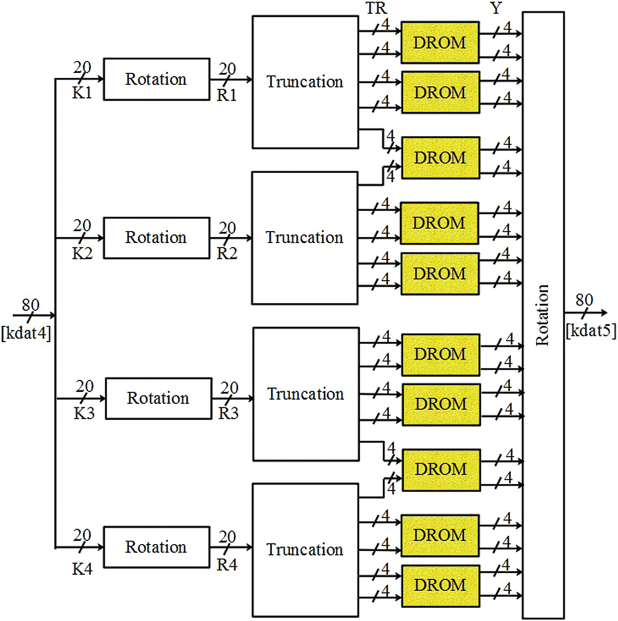
Figure 3: Architecture of key sampling process
The rotation operation provides four different 20-bit values such as
After completing the 32 rounds, the PRESENT architecture provides the encrypted cipher text that is denoted as CT. Moreover, the decrypted value is obtained based on the inverse process of PRESENT decryption. Here the reverse architecture of PRSENT module is used during the decryption process. The process of key generation using the TRNG-PRNG module is explained in the following section.
4.3 Key Generation Using TRNG-PRNG Module
In this TRNG-PRNG module, the key value is generated for each clock cycle as well as for each plain text to improve the security. The overall architecture of 80-bit key generation using TRNG-PRNG module is illustrated in Fig. 4. Generally, the TRNG is designed by the digital circuits to produce the true randomness using the unpredictable effects. Here the TRNG is generated by using the

Figure 4: Architecture of TRNG-PRNG module
Table 3: Operation of rotation

The steps processed in the key generation using TRNG-PRNG module are given as follows:
a) Initially, the TRNG-PRNG module generate the 80-bit true random number that is represented as RN0. Next, this 80-bit RN0 value is truncated into four 20 bits such as
b) The pair of truncated values such as T1 − T2 and T3 − T4 is processed under MUX operation. The output from the MUX is operated using the selection line and it is shown in Eq. (8).
where, M1 and M2 represents the MUX operation value between the pairs of T1 − T2 and T3 − T4 respectively.
c) The values from the MUX processes M1 and M2 are XORed with the 20bit values of the T1 and T4 respectively. The XOR operation between the pairs of M1 − T1 and M2 − T4 are denoted as X1 and X2 respectively as shown in Eq. (9). For example, the XOR operation between the M1 − T1 pair is shown in Tab. 4.
d) In this key generation process, one more TRNG is used to generate four 20-bit values such as
where,
e) The values of A1 − A2 and A3 − A4 are processed under XNOR operation, once the addition is completed. Eq. (11) shows the process of XNOR operation and sample XNOR operation between the pair of A1 − A2 is shown in Tab. 5.
where, X3 and X4 are the XNOR values between the A1 − A2 and A3 − A4 pair respectively.
f) One more MUX operation is carried out using 4 different inputs such as
g) Finally, the concatenation operation between the
Table 4: Sample XOR operation for M1 − T1

Table 5: Sample XNOR operation for A1 − A2

The optimization of hardware components using DROM leads to obtain the high operating frequency and less area utilization while designing the PRESENT architecture. Moreover, the generation of key for each round and each plaintext improves the robustness of the encrypted cipher text against attackers. Therefore, it is difficult to predict the original plain text without knowing key value generated from the TRNG-PRNG module.
The results and discussion of the TRNG-PRNG based PRESENT architecture is described in this section. The implementation of the PRESENT architecture along with key generation module i.e., TRNG-PRNG module is carried out using the Xilinx ISE 14.2 software. This TRNG-PRNG based PRESENT architecture is designed using the very high speed integrated circuit hardware description language and ModelSim simulator is used to perform the functional simulations. Moreover, the MATLAB R2018a software is used to convert the image file into txt file. In PRESENT architecture, the TRNG-PRNG module is used to generate the key to accomplish the encryption/decryption process. The developed PRESENT architecture supports the 80-bit key value for 64-bit input.
5.1 Performance Analysis of PRESENT-TRNG-PRNG Architecture for Different FPGA Devices
The PRESENT-TRNG-PRNG architecture is developed for 64-bit path encryption using the 80-bit key value. The 64-bit path encryption using PRESENT-TRNG-PRNG architecture is analyzed in six different Xilinx FPGA devices such as Spartan 6, Virtex 4, and Virtex 5. The sample input image considered for 64-bit path encryption is “monarch.png” highlighted in Fig. 5. Next, this sample image is converted as gray scale image and it is converted into

Figure 5: Input image

Figure 6: Gray image
The gray scale input image shown in the Fig. 6 contains totally 16384 pixels. Additionally, the gray scale image is converted into binary format using the dec2bin function. The binary format of the image is shown in Fig. 7 and this binary value is stored in the memory of the FPGA processor. The histogram of the input image obtained using

Figure 7: Binary format of gray scale image

Figure 8: Histogram for input image
Fig. 9 shows the simulation waveform obtained from the ModelSim simulator. The control signals given to the PRESENT-TRNG-PRNG architecture are clk and load. The idat and

Figure 9: Simulation waveform
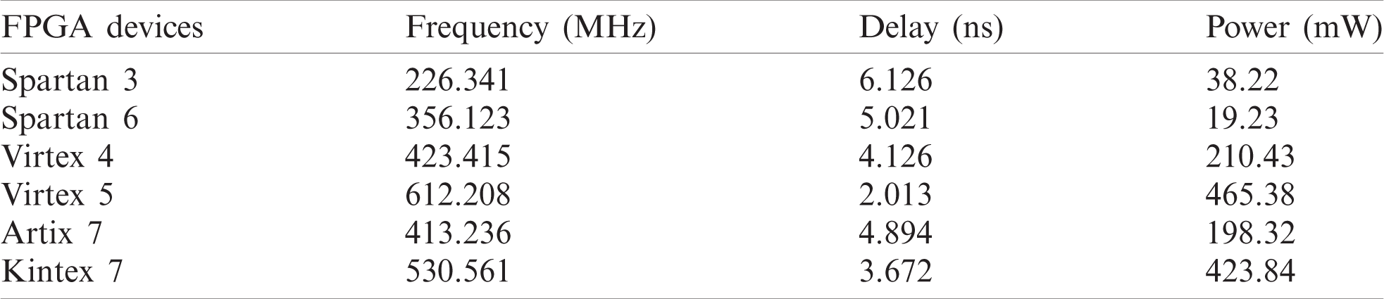
The hardware utilization, power, delay, and frequency for the different FPGA architectures are illustrated as follows:
The hardware utilization of the PRESENT-TRNG-PRNG architecture for Spartan 6 is shown in the Tab. 6. The results shown from Tab. 6 is taken for the 64-bit path encryption using 80-bit key value. The LUT, slices and flip flops for the Spartan 6 device are 45, 35 and 48 respectively. From hardware analysis, the amount of LUT used by the Spartan 6 is less as compared to the remaining five FPGA devices. If the PRESENT-TRNG-PRNG architecture is implemented in the hardware Spartan 6, the encryption output is easily verified by using the 16-output light emitting diodes present in the Spartan 6 FPGA device. The utilization of 8 DROMs instead of 16 S-boxes in PRESENT architecture helps to minimize the hardware utilization. Moreover, the analysis of frequency, delay and power are shown in the Tab. 7. These performances are evaluated for different FPGA devices. Tab. 7 shows that the PRESENT-TRNG-PRNG architecture using Virtex 5 FPGA device provides higher frequency i.e., 612.208 MHz when compared to the remaining FPGA devices. The frequency of the PRESENT architecture with Virtex 5 device increase due to the less amount of hardware utilization.
Table 6: Hardware utilization of PRESENT-TRNG-PRNG architecture in spartan 6 FPGA

Table 7: Analysis of frequency, delay and power for different FPGA devices
The encrypted binary value of input image pixel is transferred to the MATLAB R2018a software. The encrypted image using PRESENT-TRNG-PRNG architecture and its histogram count are shown in the Figs. 10 and 12, respectively. Similarly, the decrypted image and its histogram count are shown in the Figs. 11 and 13 respectively. The amount of error occurred between the input sample image to the decrypted sample are calculated using the histogram count. Moreover, the image retrieval performance of the PRESENT-TRNG-PRNG architecture are analyzed using the MSE, PSNR and SSIM. The PRESENT-TRNG-PRNG architecture obtains significant PSNR and SSIM of 49.8762 dB and 0.8211 respectively. Hence, the PRESENT-TRNG-PRNG architecture preserves the details in the image during the encryption/decryption process.

Figure 10: Encrypted image

Figure 11: Decrypted image
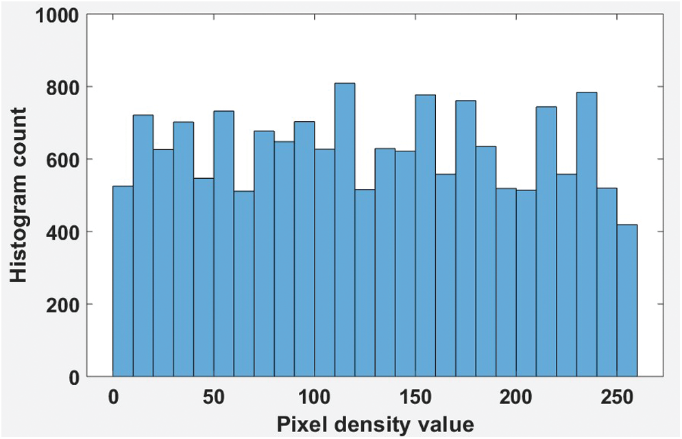
Figure 12: Histogram for encrypted image

Figure 13: Histogram for decrypted image
The effectiveness of the PRESENT-TRNG-PRNG architecture is evaluated by comparing with three existing PRESENT architecture designs. The existing methods used for the performance evaluation are PRESENT-OTF [18], PRESENT-STS [19] and PRESENT-RK [22]. The comparative analysis is accomplished by using five different FPGA devices such as Spartan 3, Spartan 6, Virtex 4, Virtex 5 and Kintex 7.
Tabs. 8 and 9 shows the comparison of the PRESENT-TRNG-PRNG architecture with the PRESENT-OTF [18], and PRESENT-RK [22] respectively. The comparison shows that the PRESENT-TRNG-PRNG architecture utilizes less amount of hardware components when compared to the PRESENT-OTF [18], and PRESENT-RK [22]. The PRESENT-STS [19] is used for high amount of S-box operation (e.g., 16 S-boxes) during encryption/decryption as well as this PRESENT-STS [19] requires additional comparator to generate the output that leads to increase the hardware utilization. But, the PRESENT-TRNG-PRNG uses only 8 DROM to accomplish the operation of the S-box. The DROM is used in both the encryption and key scheduling process that minimizes the overall hardware utilization. Moreover, the manual key generation of the PRESENT-RK [22] is vulnerable to the malicious attackers because the manually generated keys in PRESENT-RK [22] can be easily detected by the attackers. The two-stage security in the 64-bit path encryption and random key generation using TRNG-PRNG module increases the security against the malicious attackers.
Table 8: Comparison of PRESENT-TRNG-PRNG with PRESENT-OTF

Table 9: Comparison of PRESENT-TRNG-PRNG with PRESENT-RK

In this paper, the TRNG-PRNG module based key generation is accomplished in PRESENT architecture to generate the 80-bit key value to support the 64-bit of input value. Additionally, the randomness of the key obtained from the TRNG-PRNG module is increased using the two stage security during the 64-bit path encryption. Therefore, the key value used in the PRESENT-TRNG-PRNG architecture is unpredictable by the malicious attackers which improves the security of the input value. Moreover, the hardware utilization of the PRESENT architecture is minimized using the DROM to process the operation of S-box. Hence, the PRESENT-TRNG-PRNG architecture minimizes the logical elements while maintaining the higher security. The PRESENT-TRNG-PRNG architecture provides better performance when compared to the PRESENT-OTF, PRESENT-STS and PRESENT-RK. The operating frequency of the PRESENT-TRNG-PRNG is 612.208 MHz for Virtex 5, it is high when compared to the PRESENT-RK. In future, the architecture level optimization can be implemented as well as the hardware utilization and power consumption will be reduced for the entire PRESENT architecture.
Funding Statement: This research was supported by the Xiamen University Malaysia Research Fund (XMUMRF) (Grant No: XMUMRF/2019-C3/IECE/0007).
Conflicts of Interest: The authors declare that they have no conflicts of interest to report regarding the present study.
1. A. Aghaie, M. M. Kermani and R. Azarderakhsh, “Fault diagnosis schemes for low-energy block cipher Midori benchmarked on FPGA,” IEEE Transactions on Very Large Scale Integration Systems, vol. 25, no. 4, pp. 1528–1536, 2016. [Google Scholar]
2. K. Järvinen, S. S. Roy and I. Verbauwhede, “Arithmetic of $$
3. P. Kitsos, N. Sklavos, G. Provelengios and A. N. Skodras, “FPGA-based performance analysis of stream ciphers ZUC, Snow3g, Grain V1, Mickey V2, Trivium and E0,” Microprocessors and Microsystems, vol. 37, no. 2, pp. 235–245, 2013. [Google Scholar]
4. R. Chakraborty and J. K. Mandal, “An FPGA based non-feistel block cipher through recursive substitutions of bits on prime-nonprime detection of sub-stream,” Microsystem Technologies, vol. 25, no. 5, pp. 1679–1687, 2019. [Google Scholar]
5. H. M. El Hennawy, A. E. Omar and S. M. Kholaif, “LEA: Link encryption algorithm proposed stream cipher algorithm,” Ain Shams Engineering Journal, vol. 6, no. 1, pp. 57–65, 2015. [Google Scholar]
6. D. B. Roy, S. Bhasin, J. L. Danger, S. Guilley, W. He et al., “The conflicted usage of RLUTs for security-critical applications on FPGA,” Journal of Hardware and Systems Security, vol. 2, no. 2, pp. 162–178, 2018. [Google Scholar]
7. A. Aysu, E. Gulcan and P. Schaumont, “SIMON says: Break area records of block ciphers on FPGAs,” IEEE Embedded Systems Letters, vol. 6, no. 2, pp. 37–40, 2014. [Google Scholar]
8. A. Singh, N. Chawla, J. H. Ko, M. Kar and S. Mukhopadhyay, “Energy efficient and side-channel secure cryptographic hardware for IoT-edge nodes,” IEEE Internet of Things Journal, vol. 6, no. 1, pp. 421–434, 2018. [Google Scholar]
9. V. Dahiphale, H. Raut and G. Bansod, “Design and Implementation of novel datapath designs of lightweight cipher rectangle for resource constrained environment,” Multimedia Tools and Applications, vol. 78, no. 16, pp. 23659–23688, 2019. [Google Scholar]
10. D. Chakraborty, C. Mancillas-López and P. Sarkar, “STES: A stream cipher based low cost scheme for securing stored data,” IEEE Transactions on Computers, vol. 64, no. 9, pp. 2691–2707, 2014. [Google Scholar]
11. F. Pirpilidis, L. Pyrgas and P. Kitsos, “8-bit serialised architecture of SEED block cipher for constrained devices,” IET Circuits, Devices & Systems, vol. 14, no. 3, pp. 316–321, 2020. [Google Scholar]
12. V. Dahiphale, G. Bansod, A. Zambare and N. Pisharoty, “Design and implementation of various datapath architectures for the ANU lightweight cipher on an FPGA,” Frontiers of Information Technology & Electronic Engineering, vol. 21, no. 4, pp. 615–628, 2020. [Google Scholar]
13. A. Aghaie, M. M. Kermani and R. Azarderakhsh, “Reliable and fault diagnosis architectures for hardware and software-efficient block cipher KLEIN benchmarked on FPGA,” IEEE Transactions on Computer-Aided Design of Integrated Circuits and Systems, vol. 37, no. 4, pp. 901–905, 2017. [Google Scholar]
14. R. Sadhukhan, S. Patranabis, A. Ghoshal, D. Mukhopadhyay, V. Saraswat et al., “An evaluation of lightweight block ciphers for resource-constrained applications: Area, performance and security,” Journal of Hardware and Systems Security, vol. 1, no. 3, pp. 203–218, 2017. [Google Scholar]
15. N. Wu, Z. A. Ali, M. M. Shaikh, M. R. Yahya and M. Aamir, “Compact and high speed architectures of KASUMI block cipher,” Wireless Personal Communications, vol. 106, no. 4, pp. 1787–1800, 2019. [Google Scholar]
16. M. Mozaffari-Kermani, K. Tian, R. Azarderakhsh and S. Bayat-Sarmadi, “Fault-resilient lightweight cryptographic block ciphers for secure embedded systems,” IEEE Embedded Systems Letters, vol. 6, no. 4, pp. 89–92, 2014. [Google Scholar]
17. N. Thangamani and M. Murugappan, “A lightweight cryptography technique with random pattern generation,” Wireless Personal Communications, vol. 104, no. 4, pp. 1409–1432, 2019. [Google Scholar]
18. J. G. Pandey, T. Goel and A. Karmakar, “Hardware architectures for PRESENT block cipher and their FPGA implementations,” IET Circuits, Devices & Systems, vol. 13, no. 7, pp. 958–969, 2019. [Google Scholar]
19. T. De Cnudde and S. Nikova, “Securing the present block cipher against combined side-channel analysis and fault attacks,” IEEE Transactions on Very Large Scale Integration Systems, vol. 25, no. 12, pp. 3291–3301, 2017. [Google Scholar]
20. H. D. Azari and P. V. Joshi, “An efficient implementation of present cipher model with 80 bit and 128 bit key over FPGA based hardware architecture,” International Journal of Pure and Applied Mathematics, vol. 119, no. 14, pp. 1825–1832, 2018. [Google Scholar]
21. B. Rashidi, “Efficient and high-throughput application-specific integrated circuit implementations of hight and present block ciphers,” IET Circuits, Devices & Systems, vol. 13, no. 6, pp. 731–740, 2019. [Google Scholar]
22. C. A. Lara-Nino, A. Diaz-Perez and M. Morales-Sandoval, “Lightweight hardware architectures for the present cipher in FPGA,” IEEE Transactions on Circuits and Systems I: Regular Papers, vol. 64, no. 9, pp. 2544–2555, 2017. [Google Scholar]
 | This work is licensed under a Creative Commons Attribution 4.0 International License, which permits unrestricted use, distribution, and reproduction in any medium, provided the original work is properly cited. |