DOI:10.32604/cmc.2021.016175
| Computers, Materials & Continua DOI:10.32604/cmc.2021.016175 | |
| Article |
Fractional-Order Control of a Wind Turbine Using Manta Ray Foraging Optimization
1College of Engineering at Wadi Addawaser, Prince Sattam Bin Abdulaziz University, Al-Kharj, 11911, Saudi Arabia
2Department of Electrical Engineering, Faculty of Engineering, Minia University, 61517, Minia, Egypt
3Research Laboratory in Automatic Control (LARA), National Engineering School of Tunis (ENIT), University of Tunis, Tunis, 1002, Tunisia
4High Institute of Industrial Systems of Gabès, University of Gabès, Gabès, 6011, Tunisia
*Corresponding Author: Hegazy Rezk. Email: hr.hussien@psau.edu.sa
Received: 22 December 2020; Accepted: 25 January 2021
Abstract: In this research paper, an improved strategy to enhance the performance of the DC-link voltage loop regulation in a Doubly Fed Induction Generator (DFIG) based wind energy system has been proposed. The proposed strategy used the robust Fractional-Order (FO) Proportional-Integral (PI) control technique. The FOPI control contains a non-integer order which is preferred over the integer-order control owing to its benefits. It offers extra flexibility in design and demonstrates superior outcomes such as high robustness and effectiveness. The optimal gains of the FOPI controller have been determined using a recent Manta Ray Foraging Optimization (MRFO) algorithm. During the optimization process, the FOPI controller’s parameters are assigned to be the decision variables whereas the objective function is the error racking that to be minimized. To prove the superiority of the MRFO algorithm, an empirical comparison study with the homologous particle swarm optimization and genetic algorithm is achieved. The obtained results proved the superiority of the introduced strategy in tracking and control performances against various conditions such as voltage dips and wind speed variation.
Keywords: Renewable energy; modeling; wind turbine; doubly fed induction generator; fractional order control; manta ray foraging optimization
Recently, the utilization of renewable energy sources has prompted the reduction of conventional fossil-fuel energy source dependency. Wind energy as a renewable source has gained considerable attention because it is clean and pollution-free. Wind Energy Conversion Systems (WECSs) are mainly based on Wind Turbines (WTs). However, the intensive research that is executed in the wind technology market produced various wind energy configurations. The most popular configuration is the Doubly Fed Induction Generator (DFIG) linked with the WTs [1,2]. This type is vastly used due to its considerable advantages, which the decoupled control of active and reactive powers, low converters’ costs, and mechanical exertion decrease are the main ones. The DFIG is linked to the grid via a converter consisting of a Rotor Side Converter (RSC) and a Grid Side Converter (GSC). This topology enables the converter to catch the portion of 20% to 30% of the overall power resulting in reducing its cost [3,4].
Several research works have assured to reinforce the efficiency of WECSs. Among the existing control strategies, the classical Vector Control (VC) is broadly applied. This scheme allows independent control of the power components exchanging between the DFIG and the grid and keeps the DC-link voltage constant. The VC method is mostly attained by regulating the decoupled rotor converter currents using linear Proportional-Integral (PI) controllers [5,6]. The major disadvantage of this scheme is that the effectiveness of the DFIG relies on the accurate adjusting of the PI parameters and the exact values of DFIG parameters such as stator resistance, rotor resistance, and inductances [7]. Hence, the PI controllers-based VC method provides poor performance and low robustness when actual DFIG parameters deviate from the nominal values, which have been used in the control system [8].
In this regard, to outperform the drawbacks of the classical VC method based, various control structures are proposed to improve the dynamic response [9]. Therefore, the Fractional-Order (FO) PI controllers emerge as a relevant option, as demonstrated by several applications. This type of controller combines the benefits of the classical PI and fractional calculus. Therefore, this leads to better performance [10,11]. Applying a FOPI controller in the pitch angle control loop and is compared with a fuzzy PI controller has been suggested in [12]. In [13], the authors focused on attenuating the Total Harmonic Distortion (THD) value in the voltage and current signals using the FOPI controllers in the back-to-back converter. However, the design approach was not indicated. Besides, a simple wind speed profile with fixed step changes is investigated. Another solution adopting the FOPI scheme has been discussed for the active power control based DFIG in [14]. Besides, the FOPI controllers are applied in the internal loop of rotor current instead of the classical PI controllers. Also, the tuning of the FOPI controllers is executed using the frequency domain specifications. All these studies discussed the FOPI method in the presence of the L-filter at the GSC.
In this work, the FOPI controller is designed for the DC-link voltage loop in the presence of the LCL filter. This filter leads to improve the THD of the current grids [15]. Usually, the FOPI controllers have an extra adjustable parameter than the classical PI controllers. This parameter makes the controller design more complicated. Many methods are adopted for the tuning of FOPI controllers. However, most of these methods depend on the trial-errors procedure and the frequency domain specifications. However, since the FOPI controller gains rely on the mathematical representation, the control schemes become prone to error. Besides, the tuning process can be time-consuming, and the optimal gains may not be caught. To this end, the nature-inspired meta-heuristics such as Particle Swarm Optimization (PSO) and Genetic Algorithm (GA) are applied [16–18]. Therefore, this work uses a Manta Ray Foraging Optimization (MRFO) algorithm to attain the FOPI controller gains’ [19]. The main contributions of the proposed FOPI controller are: (1) It ensures high tracking performance through the selection of the optimal gains for the FOPI controller by using the recent metaheuristic MRFO algorithm. (2) It presents a fast dynamic behavior and high robustness of the closed-loop DC-link voltage loop under external disturbances such as wind speed variation and the voltage dip conditions. (3) It reduces the values of the THD of the grid currents more than the traditional PI controller.
The remainder of this paper is organized as follows. The mathematical model of DFIG based WT is detailed in Section 2. In Section 3, the description of the FOPI controller for the DC-link voltage dynamics is analyzed. Also, such an MRFO algorithm is described and given. Section 4 states the implementation of the proposed MRFO-tuned FOPI control approach. Concluding remarks are given in Section 5.
2 Modelling of the DFIG Based Wind Energy Converter
2.1 Modelling of the Wind Turbine
The rotor blade of the WT is responsible for catching the wind power and converting it into kinetic energy. The captured mechanical power is given as follows [2,3]:
where
The tip-speed ratio is defined as the ratio of the blade tip-speed to the wind speed. It is given by:
where
The dynamic equations of the DFIG model can be expressed as [2,3]:
where Vs and is are the stator voltage and current, Vr and ir are the rotor voltage and current,
In this work, the Stator Flux Orientation (SFO) is adopted to implement the power control of the DFIG. Supposing that the electrical grid is stable, the stator flux is constant. Hence, according to the above presumptions, the stator voltages and fluxes can be written as follows [3]:
where Ls, Lr, and Lm are the stator, rotor, and magnetizing inductances, respectively.
The stator power components and rotor voltages are expressed as [3,4]:
where
2.3 Modelling of the GSC and the DC-Link Circuits
The GSC is connected to the grid through an LCL-filter. However, for better understanding the control of the GSC, it is necessary to describe the model of the grid side system and DC-link parts. The mathematical formulation of the GSC in the dq synchronous frame is defined by Eq. (7). The term LTrepresents the sum of the converter Li and grid side Lg inductances. In fact, the LCL-filter can be approximated to an L-filter equal to the sum of the LCL-filter inductors [2]:
where Vdf and Vqf are the terms of the power-converter side voltage, igd and igq are the terms of the grid currents, egd and egq are the terms of the grid voltage, and RT is the sum of the converter and grid side resistors.
The DC-link circuit, which connects the GSC and RSC components, can be modeled as follows [2,9]:
where Cdc is the DC-link capacitance and irdc is the current flowing between the DFIG rotor and the DC-link. From the voltage dynamics described by Eq. (8), the DC-link voltage can be regulated via the direct grid current.
3 Control Strategy and Optimization
Generally, the classical vector control of the DFIG system is divided into the RSC and GSC control diagrams, which the PI controllers are usually used in this control scheme. The RSC is adopted to regulate the stator power components. On the other hand, the GSC is adopted to maintain the DC-link voltage constant. In this work, the FOPI controller is applied in the GSC circuit to improve its control performance. As a result, the excellent tracking performance, the reduced chattering, and the robustness of the DC-link under disturbances are improved. However, a good selection of the FOPI controller gains is a big challenge, where the optimal parameters improve the system performance. Control parameter tuning using the conventional manual trials-and-errors based approach is a time-consuming and non-systematic procedure. The manta ray foraging optimization is proposed to improve the selection of the FOPI regulator gains. The proposed FOPI based DC-link voltage for the DFIG control scheme is shown in Fig. 1.

Figure 1: The proposed control approach applied to the DFIG system
3.2 Fractional-Order PI Controller
Fractional-Order (FO) controllers gained great attention and high penetration in many applications. Presently, many researchers tried to achieve the most reliable performance of such controllers [11]. Fractional-Order Proportional-Integral-Derivative (FOPID) controller was firstly presented in [20]. It is characterized by better performance than the conventional PID one, especially for the closed-loop control process. Five parameters are required to model the PI
Referring to Fig. 2, the transfer function of the FOPID controller can be written in the following form:
where
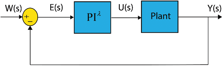
Figure 2: Block diagram of the PI
The output of the PI
The main object of the FOPI controller is to feed the plant with the desired input via minimizing the error signal fed to it (i.e., E(s) controller’s input). This can be achieved when the parameters of the PI
The parameter
Several time-domain performance metrics, i.e., maximum overshoot, steady-state error, rise, and/or settling times can be used as operational constraints for the formulated optimization problem. Such a problem deals to minimize a set of the well-known performance criteria such as Integral Absolute Error (IAE), Integral of Square Error (ISE), and Root Square Mean Error (RSME) as follows:
where
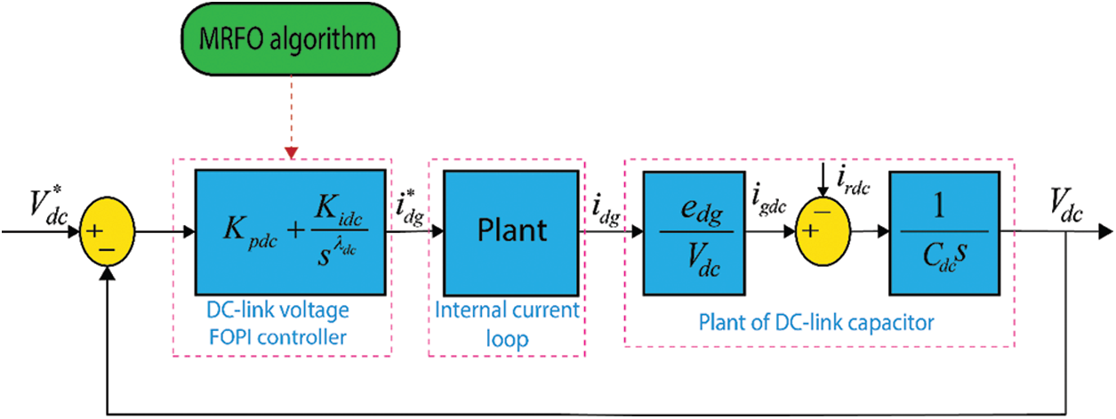
Figure 3: FOPI control scheme for the DC-link voltage based MRFO algorithm
3.3 Manta Ray Foraging Optimization
Manta rays are fancy creatures although they appear to be terrible. They are one of the largest known marine creatures. MRFO is recently suggested by Zhao et al. [19]. It is inspired by three foraging behaviors including chain foraging, cyclone foraging, and somersault foraging. The mathematical models are clearly described in [19]. During the chain foraging, manta rays line up head to tail and form a foraging chain. The individuals update their positions based on the following relations:
where
When a school of manta rays recognizes a patch of plankton in deep water, they will form a long foraging chain and swim towards the food by a spiral. The following mathematical relation can be used to simulate the spiral-shaped movement of manta rays in 2-D space:
where
This motion behavior can be extended to an n-D space. For simplicity, the model of cyclone foraging can be represented using the following relations:
where
Then, every individual search for a new position far from the current best one by assigning a new random position as following:
where Lbd and Ubd are the lower and upper limits
Lastly, in the somersault foraging, the position of the food is viewed as a pivot. Each individual tends to swim to and from around the pivot and somersault to a new location. The following relation can be representing this stage:
where S denotes the somersault factor, S = 2, r2, and r3 are random values.
This section investigates the numerical simulations executed to assess the effectiveness of the proposed MRFO-tuned FOPI controller design approach for the studied DFIG. The demonstrative control results of the active/reactive powers and DC-link voltage are discussed and analyzed. The parameters of the used DFIG system are presented in [2]. To investigate the performance of the proposed algorithm, GA and PSO algorithms are implemented, in which the number of the population size is 10, and the maximum number of iterations is 25.
Tab. 1 lists the optimization results of the problem (11). It can be clearly observed that the proposed MRFO algorithm produces the best mean solutions over the three used indices in comparison with the other algorithms. Fig. 4 shows the convergence history of the mean cost functions for the RMSE index. The MRFO algorithm outperforms the compared algorithms in terms of fastness and non-premature convergence. The Box-and-Whisker plots of the mean objective function values are presented in Fig. 5. The results of the cost function prove the superiority of the proposed MRFO algorithm. Hence, the parameters of the FOPI controller-based MRFO optimization algorithm are adopted. The active/reactive powers, DC-link voltage, and THD of the grid currents are displayed to prove the performance of the proposed FOPI controller. The demonstrative results of the FOPI controller are tested under the following conditions: (1) Variations in the DC-link reference. (2) Wind speed step variation. (3) Voltage dips conditions.
Table 1: Statistical results of optimization for the problem (11) over 30 independent runs
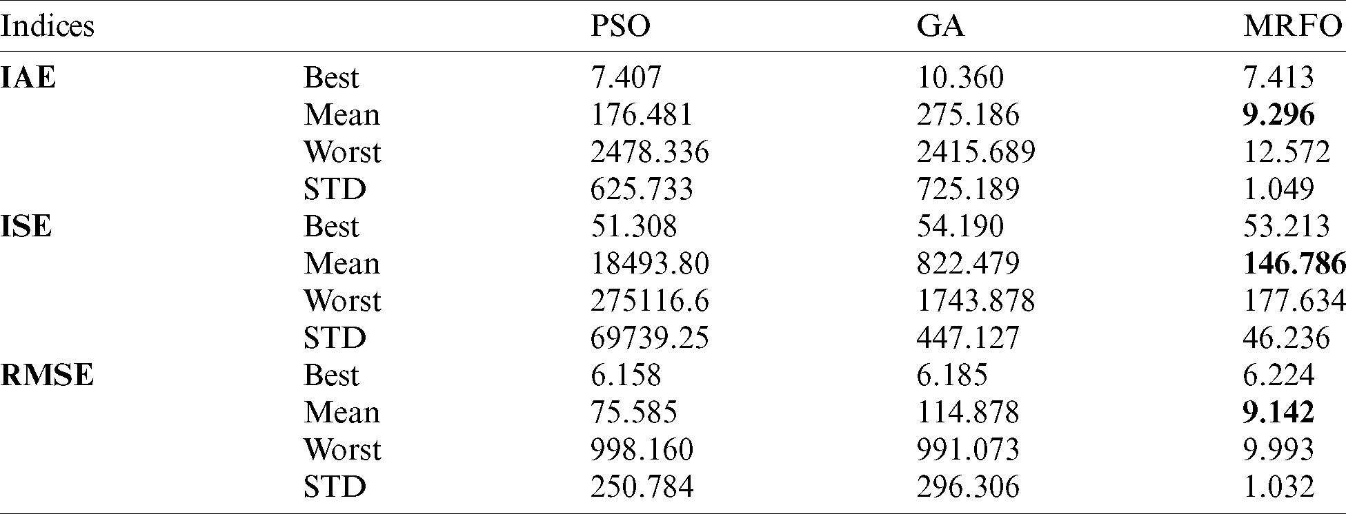
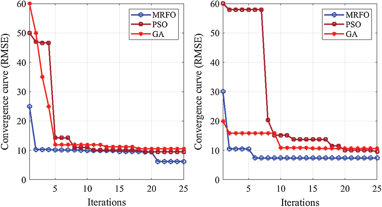
Figure 4: Convergence histories of the optimization algorithms: RMSE index
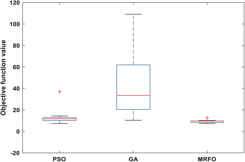
Figure 5: Box-and-Whisker plot of the optimization algorithms: RMSE index
4.1 DC-link Voltage Step Change
Fig. 6 illustrates the dynamic performance of the DC-link voltage control. From Tab. 2, it can be observed that the FOPI controller introduces the best time domain performances in terms of settling time, rise time, and overshoot minimization. Besides, it can be noted that the proposed controller reduces the chattering effect in comparison with the PI controller.
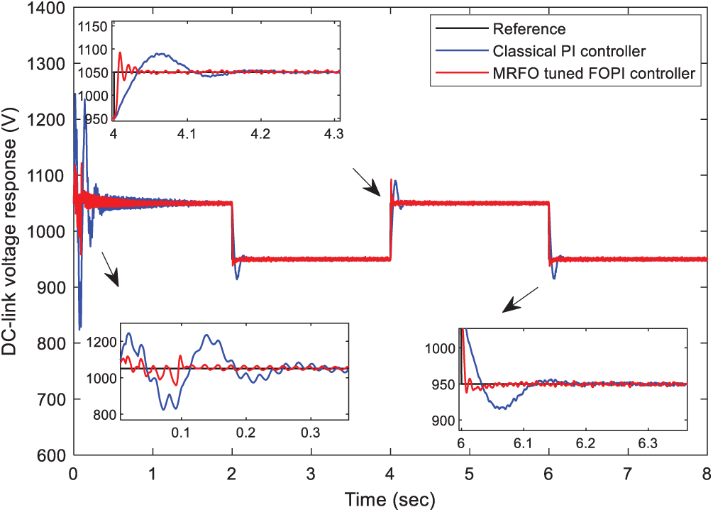
Figure 6: Performance comparison of the DC-link voltage under step changes
Table 2: Time-domain performances’ comparison for the DC-link voltage dynamics
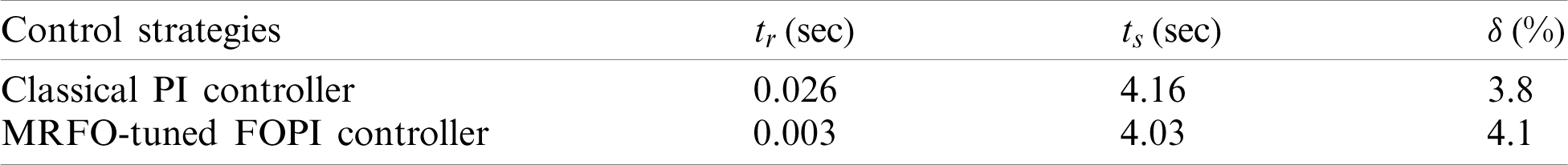
Fig. 7 shows the dynamic performance of the reactive power response. It can be noted that the decoupling between the active and reactive powers is ensured. Fig. 8 shows the THD of the grid currents for the two control strategies, which this result confirms that the proposed FOPI controller further attenuates the harmonics of the grid currents.
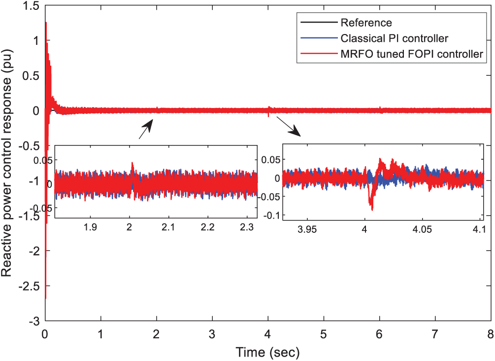
Figure 7: Performance comparison of the stator reactive power under step changes
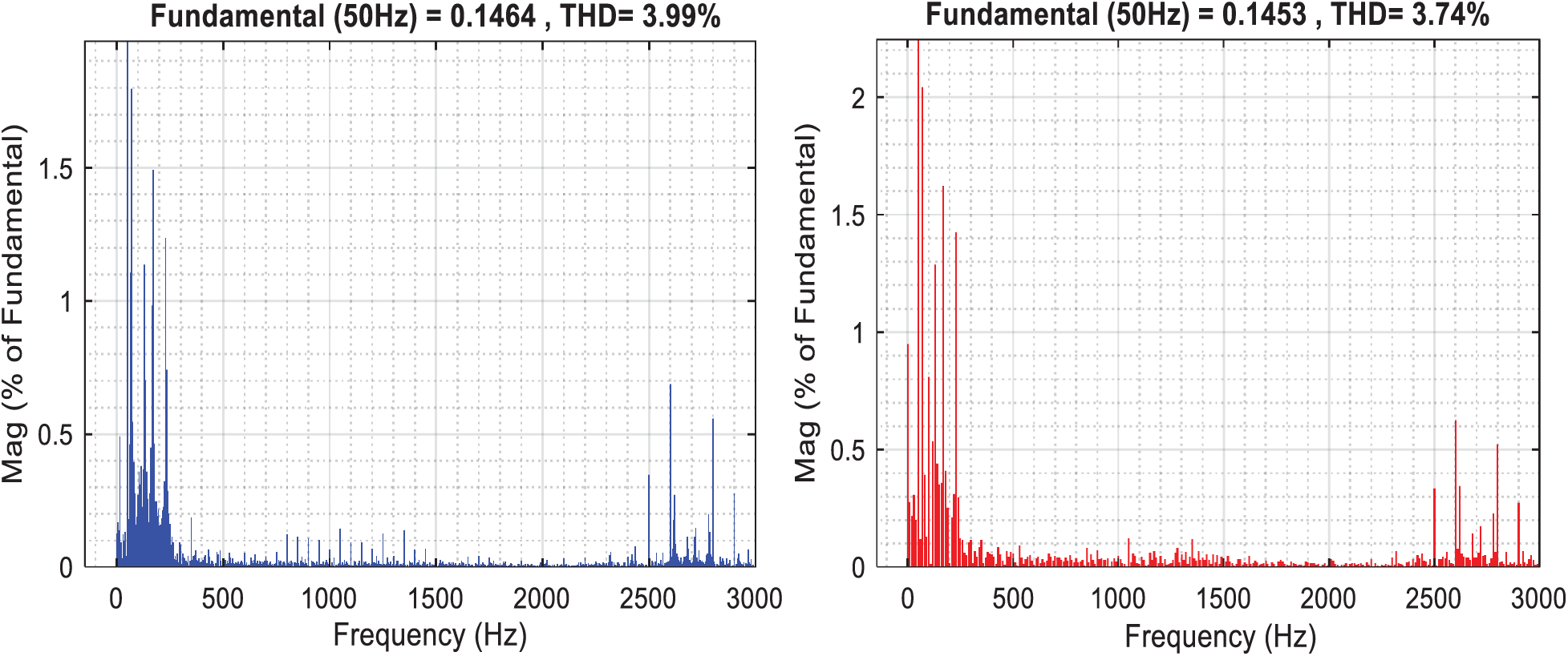
Figure 8: Grid current harmonic spectra: (a) PI controller; (b) FOPI controller
To investigate the performance of the proposed controller, the MRFO-based PI
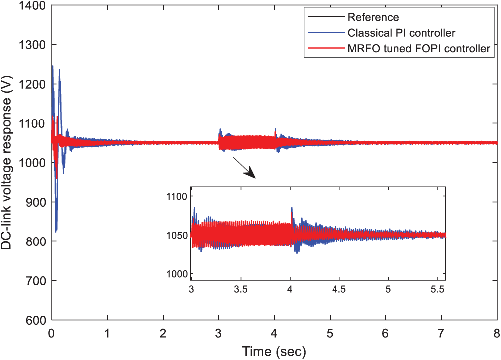
Figure 9: Performance comparison of the DC-link voltage under the voltage dip condition
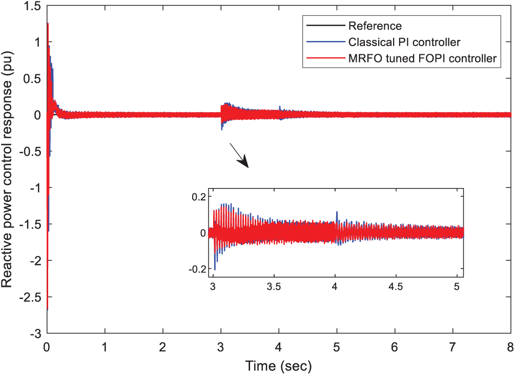
Figure 10: Performance comparison of the stator reactive power under the voltage dip condition
The step variation scenario is considered for wind speed to appraise the tracking performance of the understudy controllers. This scenario is presented in Fig. 11. Besides, Figs. 12 and 13 show the simulation results which confirm the efficiency of the MRFO-tuned FOPI. These MRFO-based PI
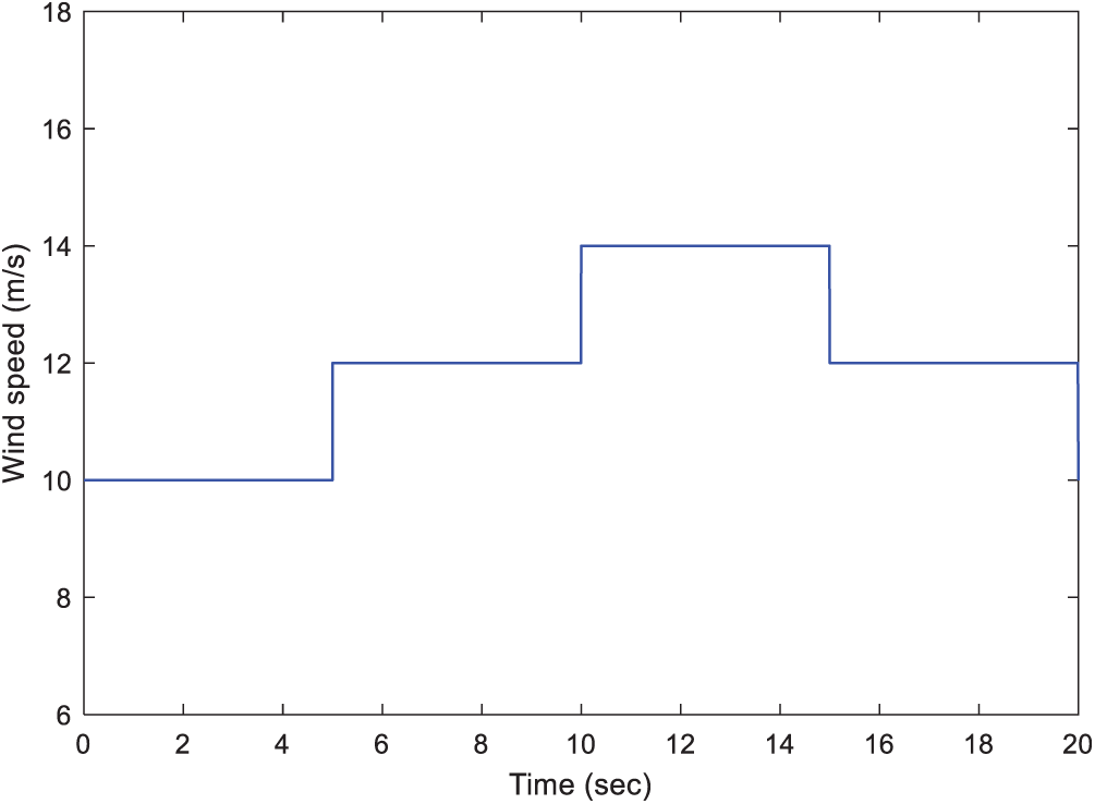
Figure 11: Wind speed step variation between 10 and 14 m/s
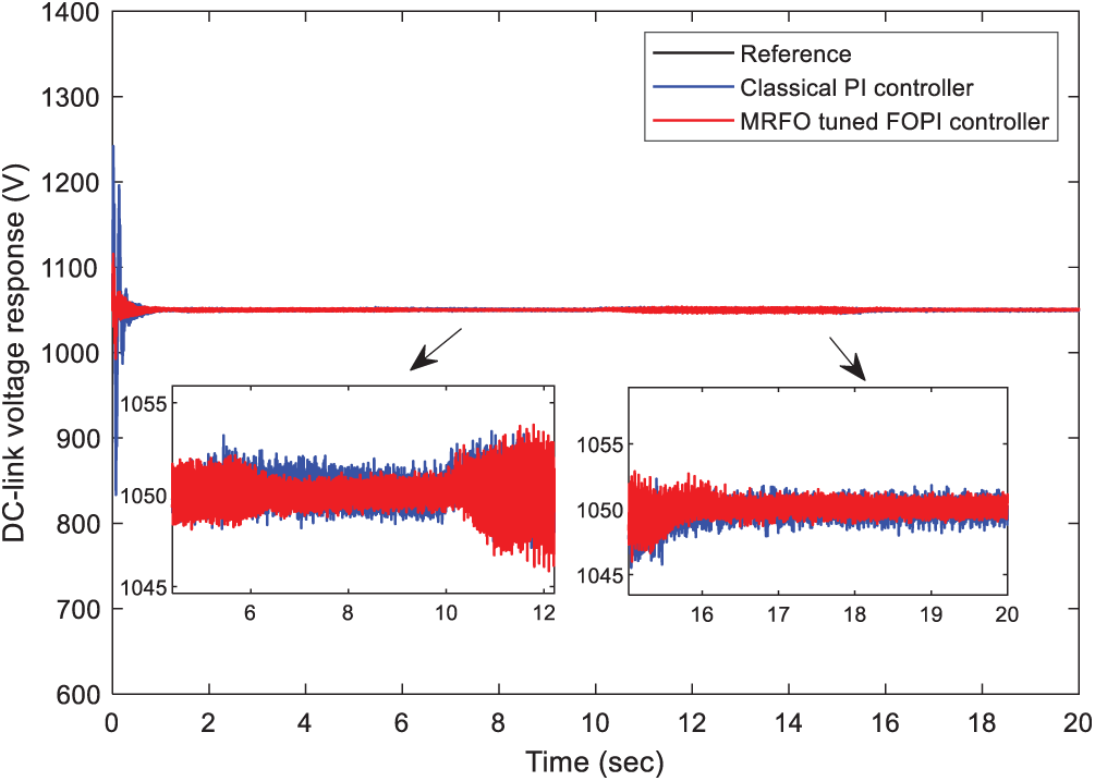
Figure 12: Performance comparison of the DC-link voltage under the wind speed step variation
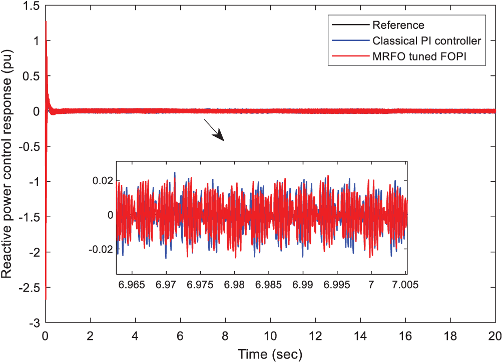
Figure 13: Performance comparison of the stator reactive power under the wind speed step variation
This research work compares the classical PI and FOPI controllers in a DFIG-based WT. The gains of the FOPI are acquired by using the MFRO meta-heuristic algorithm. The obtained results show that the FOPI controller performs better than the traditional PI in the DC-link voltage dynamics. (1) The FOPI-tuned MRFO controller needs a lower rise time and settling time, less tuning time, and better robustness with wind speed variations and voltage dip conditions. (2) The FOPI controller enhances remarkably the start-up performance and makes the system reach its steady-state region without a considerable impact. The gained results show that the proposed FOPI controller tuned-MRFO method is a promising alternative strategy for controlling the DFIG system by systematically tuning the unknown FOPI controllers’ parameters efficiently.
Funding Statement: The authors received no specific funding for this study.
Conflicts of Interest: The authors declare that they have no conflicts of interest to report regarding the present study.
1. K. A. Naik, C. P. Gupta and E. Fernandez. (2020). “Design and implementation of interval type-2 fuzzy logic-PI based adaptive controller for DFIG based wind energy system,” International Journal of Electrical Power & Energy Systems, vol. 115, no. 1, pp. 1–16. [Google Scholar]
2. M. M. Alhato, S. Bouallègue and H. Rezk. (2020). “Performance improvement of direct power control of doubly fed induction generator based wind turbine through second-order sliding mode control approach,” Mathematics, vol. 8, no. 11, pp. 1–31. [Google Scholar]
3. M. M. Alhato and S. Bouallègue. (2019). “Direct power control optimization for doubly fed induction generator based wind turbine systems,” Mathematical and Computational Applications, vol. 24, no. 3, pp. 1–27. [Google Scholar]
4. B. Hamane, M. L. Doumbia, M. Bouhamida, A. Draou, H. Chaoui et al. (2015). , “Comparative study of PI, RST, sliding mode and fuzzy supervisory controllers for DFIG based wind energy conversion system,” International Journal of Renewable Energy Research, vol. 5, no. 4, pp. 1174–1185. [Google Scholar]
5. R. Pena, J. C. Clare and G. M. Asher. (1996). “Doubly fed induction generator using back-to-back PWM converters and its application to variable-speed wind-energy generation,” IEE Proc. Electric Power Applications, vol. 143, no. 3, pp. 231–241. [Google Scholar]
6. F. Poitiers, T. Bouaouiche and M. Machmoum. (2009). “Advanced control of a doubly fed induction generator for wind energy conversion,” Electric Power Systems Research, vol. 79, no. 7, pp. 1085–1096. [Google Scholar]
7. M. El Azzaoui and H. Mahmoudi. (2017). “Fuzzy-PI control of a doubly fed induction generator-based wind power system,” International Journal of Automation and Control, vol. 11, no. 1, pp. 54–66. [Google Scholar]
8. M. M. Alhato and S. Bouallègue. (2020). “Thermal exchange optimization based control of a doubly fed induction generator in wind energy conversion system,” Indonesian Journal of Electrical Engineering and Computer Science, vol. 20, no. 3, pp. 1–8. [Google Scholar]
9. D. Zhou and F. Blaabjerg. (2017). “Bandwidth oriented proportional-integral controller design for back-to-back power converters in DFIG wind turbine system,” IET Renewable Power Generation, vol. 11, no. 7, pp. 941–951. [Google Scholar]
10. D. Horla and T. Sadalla. (2020). “Optimal tuning of fractional-order controllers based on Fibonacci-search method,” ISA Transactions, vol. 104, no. 1, pp. 287–298. [Google Scholar]
11. C. Zhao, D. Xue and Y. Q. Chen. (2005). “A fractional order PID tuning algorithm for a class of fractional order plants,” in Proc. of the IEEE Int. Conf. Mechatronics and Automation, Niagara Falls, Ont., Canada, pp. 216–221. [Google Scholar]
12. C. Viveiros, R. Melicio, J. Igreja and V. M. F. Mendes. (2015). “Performance assessment of a wind energy conversion system using a hierarchical controller structure,” Energy Conversion and Management, vol. 93, no. 1, pp. 40–48. [Google Scholar]
13. M. Hosseinabadi and H. Rastegar. (2014). “DFIG based wind turbines behavior improvement during wind variations using fractional order control systems,” Iranian Journal of Electrical and Electronic Engineering, vol. 10, no. 4, pp. 314–323. [Google Scholar]
14. H. Mahvash, S. A. Taher, M. Rahimi and M. Shahidehpour. (2018). “DFIG performance improvement in grid connected mode by using fractional order [PI] controller,” International Journal of Electrical Power & Energy Systems, vol. 96, no. 1, pp. 398–411. [Google Scholar]
15. M. M. Alhato and S. Bouallègue. (2019). “Whale optimization algorithm for active damping of LCL-filter-based grid-connected converters,” International Journal of Renewable Energy Research, vol. 9, no. 2, pp. 986–996. [Google Scholar]
16. Y. Liu, X. Yan, F. Yan, Z. Xu and W. Shang. (2020). “Sliding-mode PID control of UAV based on particle swarm parameter tuning,” Computers Materials & Continua, vol. 63, no. 1, pp. 469–487. [Google Scholar]
17. O. Mohamed Abdalla, H. Rezk and E. M. Ahmed. (2019). “Wind driven optimization algorithm based global MPPT for PV system under non-uniform solar irradiance,” Solar Energy, vol. 180, no. 1, pp. 429–444. [Google Scholar]
18. A. Assiri. (2021). “Anomaly classification using genetic algorithm-based random forest model for network attack detection,” Computers Materials & Continua, vol. 66, no. 1, pp. 767–778. [Google Scholar]
19. W. Zhao, Z. Zhang and L. Wang. (2020). “Manta ray foraging optimization: An effective bio-inspired optimizer for engineering applications,” Engineering Applications of Artificial Intelligence, vol. 87, no. 1, pp. 1–25. [Google Scholar]
20. I. Podlubny. (1999). “Fractional-order systems and PIλDμ controllers,” IEEE Transactions on Automatic Control, vol. 44, no. 1, pp. 208–214. [Google Scholar]
21. H. S. Li, Y. Luo and Y. Q. Chen. (2009). “A fractional order proportional and derivative (FOPD) motion controller: Tuning rule and experiments,” IEEE Transactions on Control Systems Technology, vol. 18, no. 2, pp. 516–520. [Google Scholar]
 | This work is licensed under a Creative Commons Attribution 4.0 International License, which permits unrestricted use, distribution, and reproduction in any medium, provided the original work is properly cited. |