DOI:10.32604/cmc.2021.016082
| Computers, Materials & Continua DOI:10.32604/cmc.2021.016082 | |
| Article |
Interference Mitigation in D2D Communication Underlying Cellular Networks: Towards Green Energy
1Department of Computer Science, Xian Jiaotong University, Xi’an, China
2Department of Cyber Security, Air University, Islamabad, Pakistan
3Department of Information and Technology, Northwest University, Xian, China
4Department of Computer Science, College of Computer Science and Engineering, Taibah University, Madinah, Saudi Arabia
5Department of Electrical Engineering, Umm Al-Qura University, Makkah, Saudi Arabia
6Department of Computer Science, Kinnaird College for Women, Lahore, 54000, Pakistan
*Corresponding Author: Abdul Rehman Javed. Email: abdulrehman.cs@au.edu.pk
Received: 22 December 2020; Accepted: 24 January 2021
Abstract: Device to Device (D2D) communication is emerging as a new participant promising technology in 5G cellular networks to promote green energy networks. D2D communication can improve communication delays, spectral efficiency, system capacity, data off-loading, and many other fruitful scenarios where D2D can be implemented. Nevertheless, induction of D2D communication in reuse mode with the conventional cellular network can cause severe interference issues, which can significantly degrade network performance. To reap all the benefits of induction of D2D communication with conventional cellular communication, it is imperative to minimize interference’s detrimental effects. Efficient power control can minimize the negative effects of interference and get benefits promised by D2D communication. In this work, we propose two power control schemes, Power Control Scheme 1 (PCS 1) and Power Control Scheme 2 (PCS 2), to minimize the interference and provide performance analysis. Simulation results observe improvements with PCS 1 and PCS 2 as compared to without using any power control scheme in terms of data rate in both uplink and downlink communication modes of Cellular User Equipment (CUE).
Keywords: Interference mitigation; green IoT; green networks; D2D; power control; spectral efficiency; reuse mode
Over the years, cellular communication networks have evolved rapidly from 1G to 5G or Next-Generation Mobile Networks (NGMN) in the last several decades. Day by day, increasing the number of connected devices and consumers, data-hungry applications push the traditional network to its very limits (Fig. 1). The Internet of things, smart homes, and more advanced applications with higher data rates and latency requirements urge academia and industry to develop a new cellular network paradigm. One which has increased capacity and faster data rates fulfill the desired requirements. The number of connected devices to the Internet will be almost 9.4 billion in 2022 [1]. It is expected that 5G will be a heterogeneous network with multiple participating technologies, including MIMO, massive MIMO, millimeter waves, femtocells, Pico cells, and D2D communication [2]. In this paper, we restrict ourselves to D2D communication, a key technology enabler for 5G heterogeneous cellular networks. D2D communication can significantly improve spectral efficiency, and less delay can enhance the network’s capacity and reliability between devices [3]. However, with the advantageous nature of D2D communication, induction of D2D communication also cause unwanted interference for primary cellular users while reusing the same resources, resultantly degrading the network’s performance. To yield the benefits of induction of D2D communication, we need to minimize interference in both uplink and downlink transmissions [4]. Proper power control helps mitigate inter or intracellular interference; thus, we can achieve the required results of the co-existence of D2D communication with conventional cellular communication [5].
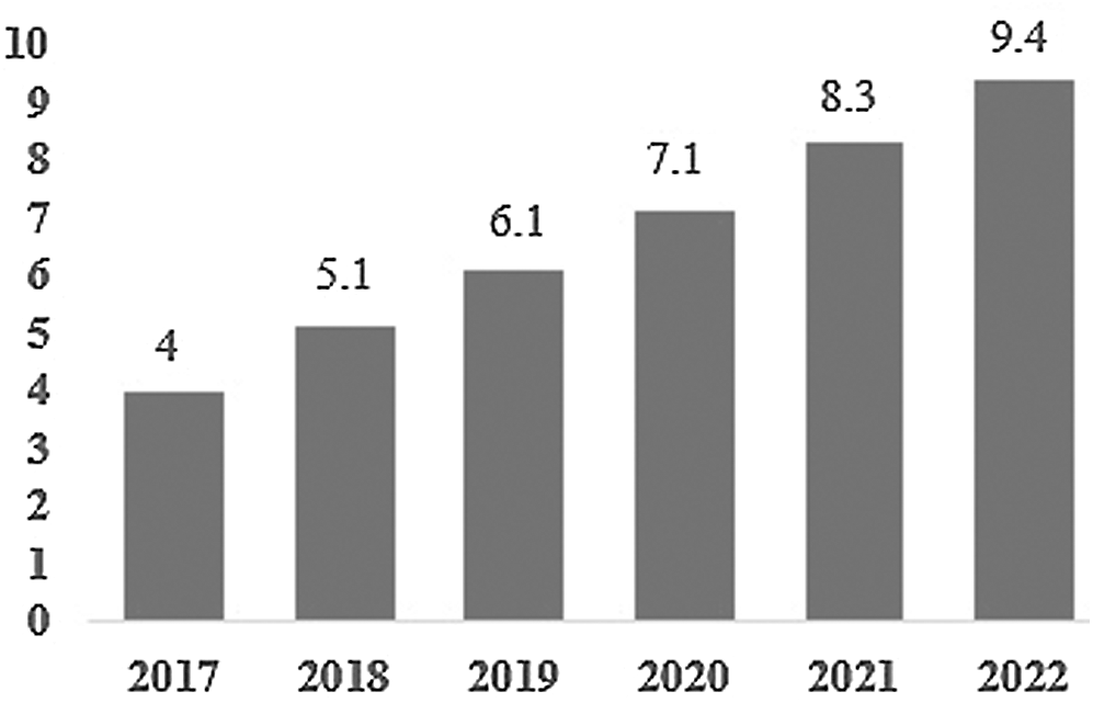
Figure 1: Expected increment in the number of connected devices till 2022
Two power control algorithms are based on stochastic geometry proposed by authors in [5] for effective power control with the intention of interference coordination and analysis performed in underlaid D2D cellular networks. The authors presented that it is possible to enhance the sum-throughput of the network with acceptable levels of interference while taking uplink transmission channels into account in a hybrid random network. A novel power control scheme was presented in [6] for hybrid cellular networks in reuse mode. This proposed mechanism relayed on putting limits on transmitting powers of D2D to minimize harmful effects from D2D devices. The study is done in a single scenario, and the results showed the possibility of increment in system capacity with the induction of D2D communication as compared to without inducing D2D communication with cellular networks. Dynamic power control scheme proposes in [7] to reduce interference and enhance overall network performance. According to the current situation in a periodic manner, power control enhances overall system throughput. In [8], the authors proposed a power control mechanism in smart grids with the induction of recent communication technologies to cope with power supply management problems. The proposed scheme’s outcomes exhibited better performance compared to existing relevant schemes.
In [9], the authors proposed an optimal joint rate and power control scheme for the cellular users intending to maximize the cellular users’ transmission data rate while protecting the D2D users from the interference caused by cellular communication. Distance-based resource allocation and power control approaches are proposed [10,11]. In [12], the authors proposed power optimization schemes to coordinate interference between communication links and prioritize cellular communication, and applied an upper limit on transmission rates for all links. Performance analyses showed prominent improvement in sum-rates in different considered scenarios. A Stackelberg game theory-based power allocation scheme is proposed in [13]. The authors considered macro and femtocells as leaders and D2D pairs as followers of this game to analyze network entities’ rational behaviors. Equilibrium of the proposed game was analyzed to determine charging prices by leaders and the proper transmit power of followers. Another joint resource and power allocation based on the Stackelberg game approach presented in [14] in which the authors considered eNB as seller and D2D pairs as buyers. Interference over Thermal (IoT) threshold being used to protect eNB from harmful interference from D2D in uplink transmission mode. In [15], the authors presented the scheme to optimize power management in the Internet of Things (IoT) networks, which are widely accepted as part of fifth-generation communication networks. Experiment results showed that the proposed scheme performed well to predict battery life better to keep network communication up to a certain level.
The motivation of this work is to develop efficient power control schemes to mitigate the interference issues so we can get all the benefits promised by the induction of D2D communication in the existing cellular networks. Although different authors proposed different schemes for different power control scenarios, we focused on dynamically power control schemes as network conditions are dynamic in real scenarios. In this work, we present two dynamic power control schemes based on a comparison between estimated Signal to Interference Plus Noise Ratio (SINR) with target SINR during uplink and downlink transmission modes to increase the data rate of the cellular user by mitigating interference caused by D2D pairs. For this purpose, we first set our system scenario and then implement our proposed schemes in this system model. Then we present a simulation result analysis of this work to compare the existing state of the artwork to show our proposed schemes’ performance.
The rest of the paper is organized as follows. Section 2 contains details about the system model. Section 3 is based on simulation results to verify our proposed power control schemes. Section 4 provides the performance of the proposed model. Finally, Section 5 describes the conclusion and future work required in this direction.
The simulations are performed for a single cell scenario where eNB is located in the cell’s center. Here
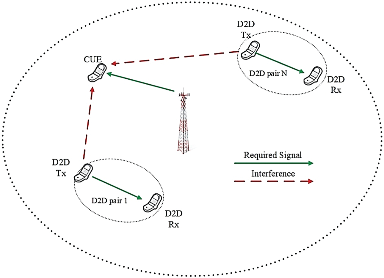
Figure 2: Downlink transmission
Fig. 3 here exhibits SINR in uplink transmission mode with PCS1, PSC2, and without any PCS. We can note that SINR values are better when we used proposed schemes, power control scheme 1 (PCS1) and power control scheme 2, compared to SINR values without power control. SINR values are decreasing with the increment in the number of D2D pairs, but still, both proposed schemes performed better. As we can see, when the number of D2D pairs increased to 10, SINR values decreased from 5 to 3.6 dB, 2.2 and 1.7 dB for PCS 1, PCS 2, and PCS, respectively.
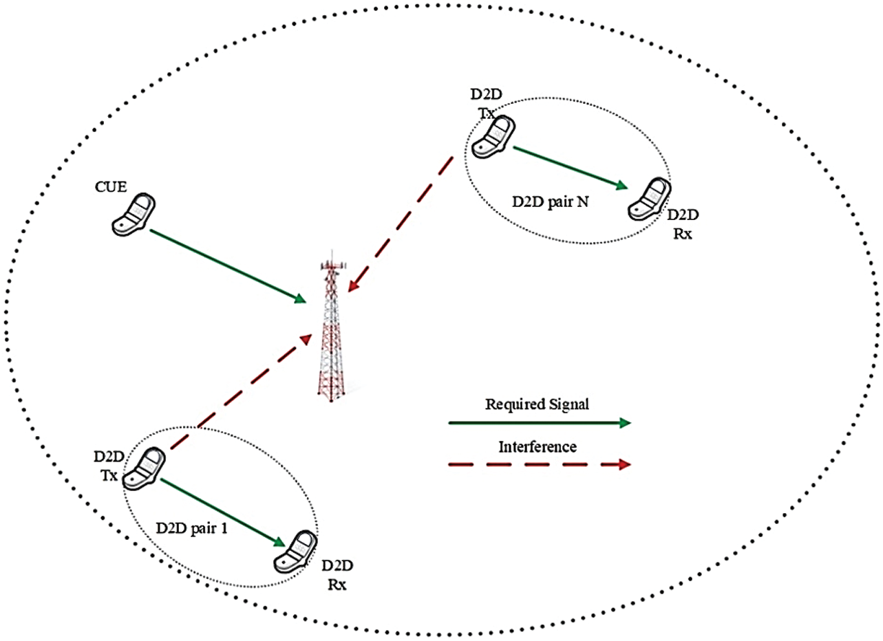
Figure 3: Uplink transmission
Similarly, in the second scenario of uplink communication mode, D2D users will cause interference for eNB, as shown in Fig. 3. Let us first discuss the scenario given in Fig. 2, which is downlink transmission. Suppose PB denotes power transmitted by eNB in downlink transmission.
Here, GB, X, and GYj, X denotes channel gain between eNB to
Where PLB, X represents Pathloss between eNB and CUE.
Where PLY, X: represents Pathloss between D2D pair and CUE.
While
Eq. (4) formulates distance from D2D Tx to CUE. Signals received at CUE in a downlink can be formulated, as in [13].
In Eq. (5), hB, hY represents signals transmitted from eNB and D2D pair, respectively.
Eq. (6) calculates propagation loss in different communication links, i.e., from D2D tx to eNB or from CUE to eNB and vice versa. Here d is the distance between different entities of the network in Km. i.e., the distance between D2D and CUE or distance between CUE and eNB, and so on.
Eq. (7) helps to calculate propagation loss between the D2D transmitter and the D2D receiver. Here d is the distance between D2D transmitter and receiver in Km. SINR in downlink transmission at CUE can be formulated as
Here
In Eq. (9)
3 Proposed Power Control Schemes
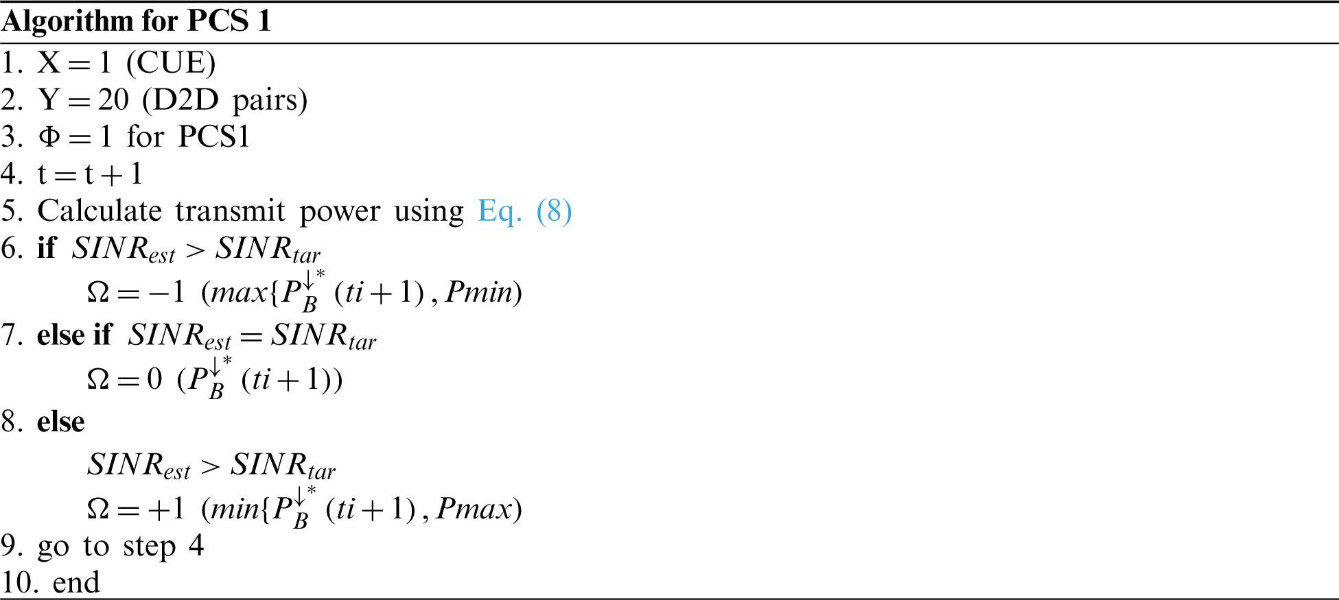
Proper power control can play a vital role in minimizing interference between different network entities in uplink and downlink, and the improvement of network performance can be achieved. In this work, power control is applied to both sides, i.e., cellular network and D2D communication. To minimize interference, the transmitted power of the desired transmitter, i.e., (eNB, D2D Tx) can be adjusted according to the current situation. Let us suppose first we consider adjusting the transmit power of eNB. In the case of eNB, the transmit power of eNB can be calculated using Eq. (1). As we can see in Eq. (8) the transmit power of eNB at the time frame of transmission
The values of
Here
Pmax and Pmin represent maximum power and minimum power. Eq. (12) guarantees the output power of PCS within the allowed transmit power limits of D2D Tx and eNB. In the case of power control at D2D, the Eqs. (10)–(12) can be used after changing indices accordingly.
3.1 Power Control Scheme 1 (PCS 1)
Power control scheme 1 is simpler and can be implemented easily. In previous work [17], a similar scheme was used in the femtocell and macro-cell scenario. Here
:
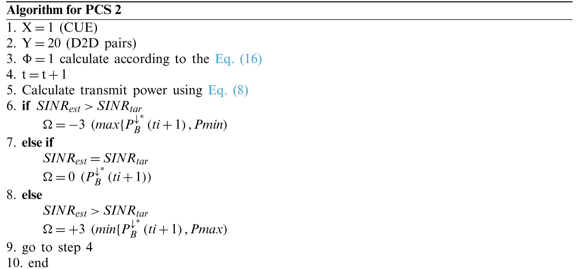
3.2 Power Control Scheme 2 (PCS 2)
In power control scheme 2, different values of
Here the idea of using various values of
With the help of Eq. (15), we can calculate the value of
:
Simulations were performed to exhibit interference mitigation in a cellular network with induction of D2D communication as an underlay. In a single-cell scenario where eNB is located in the cell’s center. In 1 km (1000 m) of the coverage area of a cell, the location of D2D pairs randomizes ten times in each simulation. The value of
Table 1: Simulation parameters
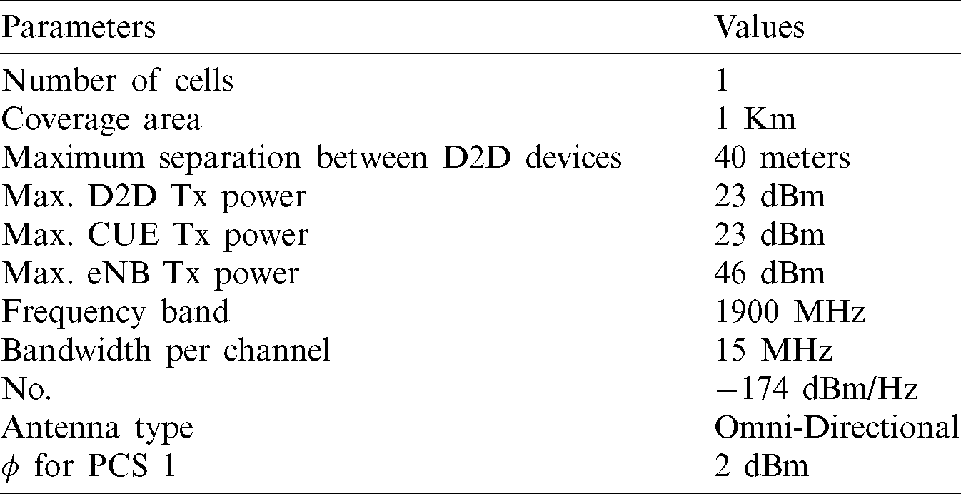
In this scenario, Quality of Service (QoS) parameters like a signal to interference plus noise ratio at receiving end formulated at receiving devices in DL can be used. Similarly, in the second scenario, we considered power control in downlink transmission mode. In this scenario, a single eNB located in the center of the cell sends signals to CUE while D2D transmitters send signals to their corresponding D2D receivers. Here transmission signals from different D2D transmitters will interfere with CUE, and as a resulted network performance can degrade. This scenario uses the same QoS parameters formulated in the downlink scenario and as used in the uplink scenario.
Fig. 4 here exhibits SINR in uplink transmission mode with PCS1, PSC2, and without any PCS. Power control plays a crucial role in managing interference when both cellular and D2D pair are sharing resources. It is clear from Fig. 3 that SINR values are better when we used our proposed schemes, power control scheme 1 (PCS1) and power control scheme 2, compared to SINR values without power control. This shows proper power control helps the efficient utilization of resources, and thus we can achieve all the benefits promised after induction of D2D communication in a conventional cellular network. SINR values are decreasing with the increment in the number of D2D pairs, but still, both proposed schemes performed better. We can see this decreasing trend in all the simulation graphs as the number of D2D pairs increases, but it is clear that the decreasing trend is a bit slower in the case of both proposed schemes. As we can see, when the number of D2D pairs increased to 10, SINR values decreased from 5 to 3.6 dB, 2.2 and 1.7 dB for PCS 1, PCS 2, and PCS, respectively. Thus, it is evident that both proposed schemes outperformed the normal conditions when there is no power control algorithm is applied.
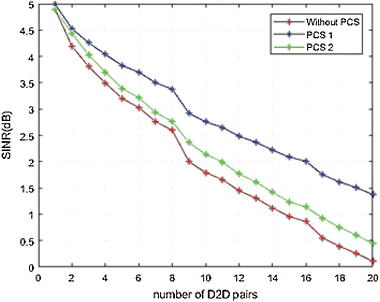
Figure 4: SINR in UL transmission mode
Similarly, Fig. 5 represents SINR values in the downlink transmission mode. Normally there is more signaling overhead as eNB sends control signals in downlink transmission mode, so it is more critical to handle resource sharing in the downlink communication channel. Otherwise, it can degrade network performance drastically. It can be observed that both proposed power control schemes performed well in downlink transmission mode too. Although it can be seen that all three graphs are following the decreasing trend as the number of D2D pairs are increasing but still performance decreasing trend is slower in the case of both proposed schemes. Performance decrement is a bit rapid when there is no power control scheme applied. For example, when the number of D2D pairs increased to 10, SINR values decreased from 25.15 to 25.02 dB, 25 and 24.9 dB for PCS 1, PCS 2, and with PCS, respectively. It indicates the SINR graph curves are less steep with our proposed power control schemes than without using any power control scheme.
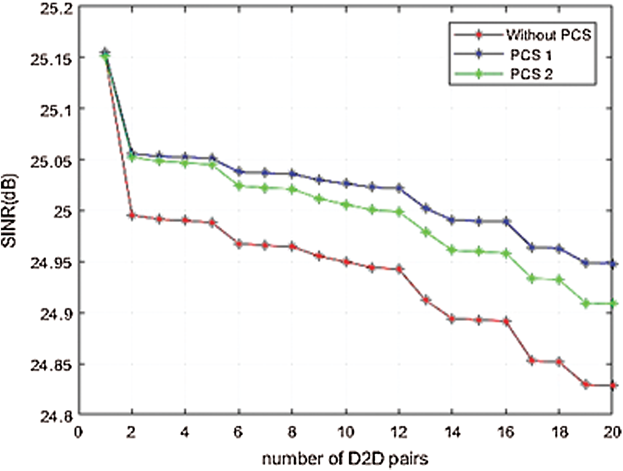
Figure 5: SINR in DL transmission mode
As we can note from Fig. 6, the CUE data rate in uplink transmission mode improved up to 0.40% and 0.20% with PCS 1 and PCS 2, respectively. Similarly, in downlink transmission mode, we can note an improvement in the CUE data rate up to 0.48% and 0.35% with PCS1 and PCS2, respectively. Thus, these simulation results showed that both power control schemes can maintain better SINR levels and can bear more no. of D2D pairs with a lesser decrement in CUE data rates in both uplink and downlink transmission modes. As a result, interference mitigation achieved an inefficient way for better performance of our network, and our aim to enhance the data rate of CUE while facilitating more no. of D2D pairs is achieved.
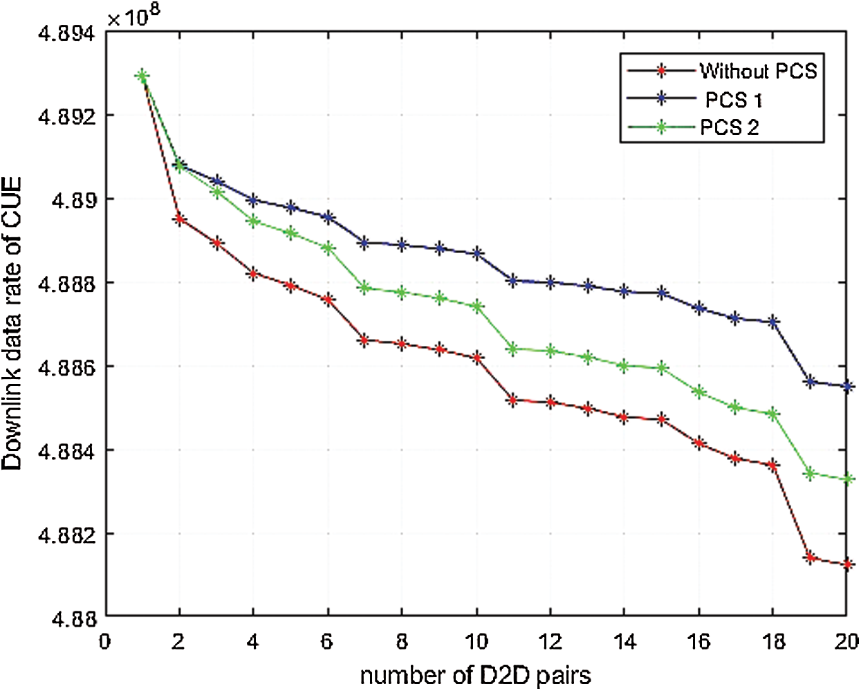
Figure 6: CUE data rate in uplink
Fig. 6 exhibits the data rate of CUE in uplink while the number of D2D pairs is increasing, and it is considered that the maximum 20 pairs of D2D pairs can be induced to share resources. Without any power control scheme, the induction of more and more D2D pairs creates more trouble for CUE in terms of interference results in the decrement of the data rate of CUE. While it can be seen that with the help of proposed power control schemes, the CUE data rate can be maintained to a bit higher level even if no. of D2D pairs is increasing. The simulation graphs show a decreasing trend in all the cases because an increasing number of D2D pairs create more disturbance for CUE. It can be noticed in Fig. 5 that more D2D users can be induced with lesser degradation of network performance with the help of proposed schemes. Thus, it is clear that proper power control can help induce more D2D pairs into the network to share resources, resulting in better performance of the network in terms of enhanced data rate.
In Fig. 7, it can be noticed that proposed power control schemes PCS1 and PCS2 performed well in downlink communication mode while the number of D2D pairs is increasing as compared to when there is no power control scheme deployed in the same scenario. As we can note from Fig. 5, the data rate of CUE in uplink transmission mode improved up to 0.40% and 0.20% with PCS 1 and PCS2, respectively. Similarly, in downlink transmission mode, we can note the CUE data rate improvement up to 0.48% and 0.35% with PCS1 and PCS2, respectively. Thus, these simulation results showed that both power control schemes can maintain better SINR levels and can bear more no. of D2D pairs with a lesser decrement in CUE data rates in both uplink and downlink transmission modes. As a result, interference mitigation is achieved in an efficient way for better performance of the network, and our aim to enhance the data rate of CUE while facilitating more no. of D2D pairs is achieved.
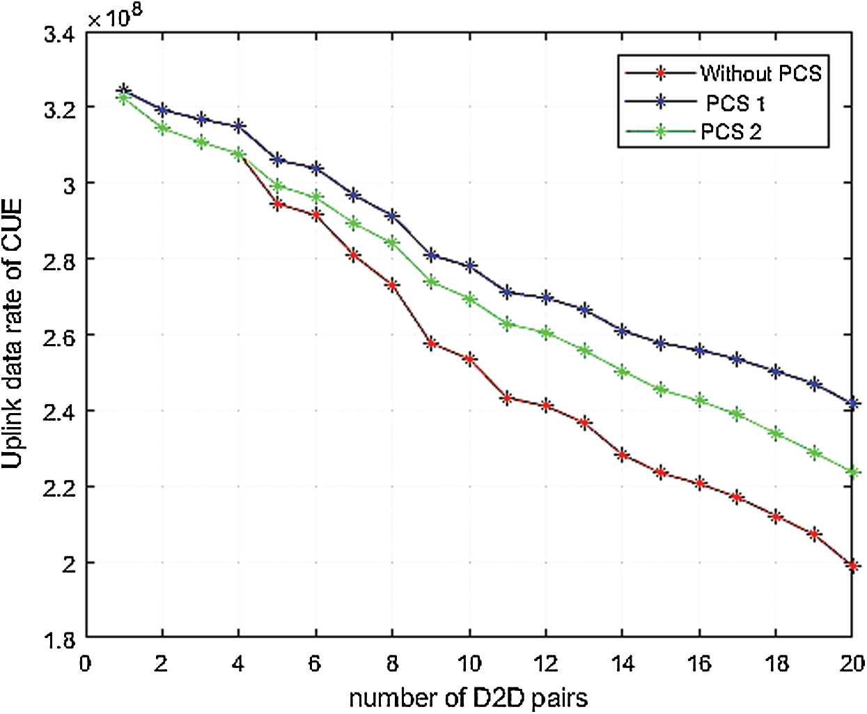
Figure 7: CUE data rate in downlink
D2D is one of the promising technologies of next-generation wireless communication networks, and it is critical to deal with the complexities and challenges that the network faces after induction of D2D in conventional cellular networks. In this work, we proposed two power control schemes (PCS1 & PCS2) to mitigate the interference in D2D communication, and simulation results show that both schemes performed well in terms of maintaining SINR levels and bearing induction of more D2D pairs with improved CUE data rates in both communication links. Proper power control can help efficient resource sharing, which results in better performance of the network in terms of better SINR levels and improved data rates. Game theory is an analytical tool that is currently used by many researchers in their work to analyze the rational and irrational behaviors of different network entities for better decision making dynamically. In the future, an extension of this work for further improvement of this work is using game theory, which is helpful in intelligent decision making.
Funding Statement: The authors would like thanks to the Deanship of Scientific Research at Umm Al-Qura University for supporting this work by Grant Code: 19-ENG-1-01-0015.
Conflicts of Interest: The authors declare that they have no conflicts of interest to report regarding the present study.
1. Last accessed 16 September 2020, . [Online]. Available: www.cisco.com/c/en/us/solutions/collateral/service-provider/visual-networking-index-vni/white-paper-c11-741490. [Google Scholar]
2. M. I. Zahoor, Z. Dou, S. B. H. Shah, I. U. Khan, S. Ayub et al. (2020). , “Pilot decontamination using asynchronous fractional pilot scheduling in massive MIMO Systems,” Sensors, vol. 20, no. 21, pp. 6213. [Google Scholar]
3. P. Gandotra and R. K. Jha. (2016). “Device-to-device communication in cellular networks: A survey,” Journal of Network and Computer Applications, vol. 71, no. 4, pp. 99–117. [Google Scholar]
4. G. Fodor, E. Dahlman, G. Mildh, S. Parkvall, N. Reider et al. (2012). , “Design aspects of network assisted device-to-device communications,” IEEE Communications Magazine, vol. 50, no. 3, pp. 170–177. [Google Scholar]
5. N. Lee, X. Lin, J. G. Andrews and R. W. Heath. (2014). “Power control for d2d underlaid cellular networks: Modeling, algorithms, and analysis,” IEEE Journal on Selected Areas in Communications, vol. 33, no. 1, pp. 1–13. [Google Scholar]
6. J. Pekka, Y. Chia-Hao, R. Cassio, W. Carl, H. Klaus et al. (2009). , “Device-to-device communication underlaying cellular communications systems,” International Journal of Communications, Network and System Sciences, vol. 2, no. 3, pp. 169–178. [Google Scholar]
7. J. Gu, S. J. Bae, B. G. Choi and M. Y. Chung. (2011). “Dynamic power control mechanism for interference coordination of device-to-device communication in cellular networks,” in Third Int. Conf. on Ubiquitous and Future Networks, Dalian, China, IEEE, pp. 71–75. [Google Scholar]
8. M. Alazab, S. Khan, S. Somayaji, Q. V. Pham, P. K. Reddy et al. (2020). , “A multidirectional LSTM model for Predicting the stability of a smart grid,” IEEE Access, vol. 8, pp. 85454–85463. [Google Scholar]
9. H. Song, J. Y. Ryu, W. Choi and R. Schober. (2015). “Joint power and rate control for device-to-device communications in cellular systems,” IEEE Transactions on Wireless Communications, vol. 14, no. 10, pp. 5750–5762. [Google Scholar]
10. Q. Duong and O. S. Shin. (2013). “Distance-based interference coordination for device-to-device communications in cellular networks,” in The Fifth Int. Conf. on Ubiquitous and Future Networks, Da Nang, Vietnam, IEEE, pp. 776–779. [Google Scholar]
11. M. C. Lucas-Estan and J. Gozálvez. (2017). “Distance-based radio resource allocation for device-to-device communications,” in IEEE 85th Vehicular Technology Conf., Sydney, NSW, Australia, IEEE, pp. 1–5. [Google Scholar]
12. C. H. Yu, O. Tirkkonen, K. Doppler and C. Ribeiro. (2009). “Power optimization of device-to-device communication underlaying cellular communication,” in IEEE Int. Conf. on Communications, Dresden, Germany, pp. 1–5. [Google Scholar]
13. Y. He, X. Luan, J. Wang, M. Feng and J. Wu. (2014). “Power allocation for d2d communications in heterogeneous networks,” in 16th Int. Conf. on Advanced Communication Technology, Pyeongchang, South Korea, pp. 1041–1044. [Google Scholar]
14. C. Xia, S. Xu and K. S. Kwak. (2014). “Resource allocation for device-to-device communication in lte-a network: A stackelberg game approach,” in EEE 80th Vehicular Technology Conf., Vancouver, BC, pp. 1–5. [Google Scholar]
15. P. K. R. Maddikunta, G. Srivastava, T. R. Gadekallu, N. Deepa and P. Boopathy. (2020). “Predictive model for battery life in IoT networks,” IET Intelligent Transport Systems, vol. 14, no. 11, pp. 1388–1395. [Google Scholar]
16. S. Y. Shin and T. A. Nugraha. (2013). “Cooperative water filling (coopwf) algorithm for small cell networks,” in Int. Conf. on ICT Convergence, Jeju, South Korea, pp. 959–961. [Google Scholar]
17. M. Susanto, H. Fitriawan, A. Abadik and Herlinawati. (2017). “On the reduction of interference effect using power control for device-to-device communication underlying cellular communication network,” in Int. Conf. on Electrical Engineering and Computer Science, Palembang, Indonesia, pp. 28–32. [Google Scholar]
 | This work is licensed under a Creative Commons Attribution 4.0 International License, which permits unrestricted use, distribution, and reproduction in any medium, provided the original work is properly cited. |