DOI:10.32604/cmc.2021.014190
| Computers, Materials & Continua DOI:10.32604/cmc.2021.014190 | |
| Article |
Quality of Service Aware Cluster Routing in Vehicular Ad Hoc Networks
1Department of Computer Science, Abdul Wali Khan University Mardan, Mardan, 23200, Pakistan
2Department of Computer and Information Technology, Sarhad University of Science and Information Technology, Peshawar, 25000, Pakistan
3Department of Computer Science, Islamia College Peshawar, Peshawar, 25000, Pakistan
4Institute of Computing, Kohat University of Science and Technology, Kohat, 2600, Pakistan
5Department of Information Technology, College of Computers and Information Technology, Taif University, Taif, 21944, Saudi Arabia
*Corresponding Author: Fasee Ullah. Email: faseekhan@gmail.com
Received: 04 September 2020; Accepted: 15 December 2020
Abstract: In vehicular ad hoc networks (VANETs), the topology information (TI) is updated frequently due to vehicle mobility. These frequent changes in topology increase the topology maintenance overhead. To reduce the control message overhead, cluster-based routing schemes are proposed. In cluster-based routing schemes, the nodes are divided into different virtual groups, and each group (logical node) is considered a cluster. The topology changes are accommodated within each cluster, and broadcasting TI to the whole VANET is not required. The cluster head (CH) is responsible for managing the communication of a node with other nodes outside the cluster. However, transmitting real-time data via a CH may cause delays in VANETs. Such real-time data require quick service and should be routed through the shortest path when the quality of service (QoS) is required. This paper proposes a hybrid scheme which transmits time-critical data through the QoS shortest path and normal data through CHs. In this way, the real-time data are delivered efficiently to the destination on time. Similarly, the routine data are transmitted through CHs to reduce the topology maintenance overhead. The work is validated through a series of simulations, and results show that the proposed scheme outperforms existing algorithms in terms of topology maintenance overhead, QoS and real-time and routine packet transmission.
Keywords: QoS; VANETs; routing; real-time communication; IoT
Vehicles can directly communicate with one another in peer-to-peer (P2P) mode or communicate indirectly via roadside infrastructure [1]. Roadside infrastructure and vehicles must be equipped with special onboard devices for the security and safety of passengers, and wireless technologies should be standardised to provide entertainment to them. Thus, research on VANETs has been attracting growing interest not only in algorithmic terms but also in terms of standards, such as IEEE 1609 and IEEE 802.11 p. There are two categories of VANET applications: (1) safety apps, which enable vehicles to exchange information such as road conditions, traffic jams, fast stops and road accidents; (2) comfort apps, which enable vehicles to check e-mails, surf the Internet, help find parking spaces and provide video and audio entertainment [2].
In this scheme, time-critical data are transmitted to the destination through the QoS shortest path in a greedy fashion when they are detected. Delay-tolerant data are transmitted to the destination through CHs to reduce the control message overhead produced with topology changes [3]. These topology changes are locally adjusted and will not be broadcasted throughout the network. Because of its hybrid nature, our proposed protocol performs better than existing algorithms in terms of providing QoS and reducing topology maintenance overhead. A series of simulations is performed to evaluate the performance of the proposed scheme, and the results are presented in the form of graphs. The simulation findings show that the proposed hybrid scheme for VANET outperforms state-of-the-art clustering and routing schemes.
The rest of this paper is organised as follows. Section 2 explores the existing literature on real-time communication and cluster-based routing in VANETs, and the major findings are presented. Section 3 discusses the proposed work on providing QoS in VANETs. Section 4 analyses the simulation results, and this paper is concluded in Section 5.
Given the high density and mobility of nodes in VANETs, there are ongoing discussions on the viability of applications using seamless multi-hop communication. The key issue is determining whether a VANET’s routing protocol efficiency meets the threshold throughput and delays for these applications. Evaluations of conventional routing protocols used in mobile ad hoc networks (MANETs) reveal that they perform poorly in VANETs [4]. The major issue with such protocols, such as ad hoc on-demand distance vector (AODV) and dynamic source routing (DSR), is the route instability in VANET scenarios. The conventional node-centred approach to routing (a defined path is a set chain of nodes from the origin to the destination) results in frequent route interruptions due to the high node mobility in VANETs. As a result, many parcels can be dropped, and the overhead caused by repairs to routes or error messages can rise considerably, resulting in low deliveries and long delays in transmission [5].
Another solution is to use geographic routing protocols, such as greedy other adaptive face routing (GOAFR) [6], greedy perimeter stateless routing (GPSR) [7] and greedy-face-greedy (GFG) [8], which uncouple the forward operation and identity of the node. Instead of determining routes, these protocols utilise the locations of the target and the neighbouring peers for data forwarding. In contrast to node-centred routing, the benefit of geographic routing is that every node which secures propagation to the target can forward data. Although route stability has improved, the geographical forwarding performance remains poor in the city’s VANETs [7]. The issue is that the next hop is not always found (closest to the target instead of the currently selected node). For example, they can use roads which fail to reach their target. The restoration techniques described in the literature rely mostly on planar plot traversals that have proven inadequate for VANETs caused by radio barriers, increased node mobility, restricted vehicle positions on the road and the uneven distribution throughout a geographical zone [7]. In addition to these limitations, the topology maintenance overhead is very high. Clustering schemes can be used to reduce the control message overhead and enable scalability.
A strong algorithm for clustering would need to emphasize the formation of a minimal set of clusters and the dynamic maintenance of the clusters’ structure without the need for additional network communications [9]. Therefore, a hybrid scheme is proposed in this paper to cope with topology dynamics and provide QoS guarantee.
In VANETs, the topology maintenance overhead can be minimised by grouping the nodes into clusters. In this way, the size of the routing tables (RTs) will be reduced. The TI is maintained at the cluster level, and all the data are communicated to the destination via CHs. However, communication via CHs may create possible delays. Delays must be avoided in cases of real-time or time-critical data of interest. In this research, the real-time data are transmitted to the destination directly through QoS shortest paths while normal data are sent to the destination on a first-come/first-served basis.
The CHs are selected based on vehicle mobility using the honeybee algorithm, as in our previous research on MANETs [10] and VANETs [11]. In this scheme, the bees are represented by vehicles. The vehicle (bee) with a high value of nectar (relative mobility) is the CH (CH). The main responsibility of scout bees is the exploration of new CHs. The dance of onlooker bees has been observed to identify vehicles with high values of nectar. The employed bees collect data after the successful selection of CHs. In other words, the most suitable CH set Ci ( ) selection. The minimisation function used in honeybee-algorithm-based clustering is used to evaluate the fitness of the solution (CHs) [10]. The working mechanism of CH selection is described by Algorithm 1. The symbols used in Algorithm 1 are described in Tab. 1.

Table 1: Symbols used in Algorithm 1

Several parameters must be configured to obtain the optimal CH set [12]: The total number of vehicles (bees) (n), the nomination of spots out of n visited spots for neighbourhood search (m), the total number of employed bees for the top e spots ( ), the number of elite spots between m designated spots (e), the total number of employed bees for the other elected sites (
 ) and the ending criterion (max).
In the beginning, inhabitants of n scout bees are hired. Every individual (bee) denotes a probable CH set. Many CHs (bees) are nominated randomly in the beginning. Their fitness is evaluated on the objective function. The bee (CH) with the most optimal solution (minimum fitness value) is selected. After the CH selection, the association of nodes with the CHs is identified. The member nodes join the cluster in which they reside. The CH can now determine the number of nodes it will serve. The initial clusters are formed in this way. Subsequently, the fitness of a spot for neighbourhood search will be calculated by the objective function, which is inversely related to the fitness.
The selection of spots for the neighbourhood search is based on the fitness value. The spots with high values of fitness are selected. The fitness value can then be used for selecting the best spots. The bees with high fitness values are selected for the next population. Hence, the next generation consists of vehicles or bees with high fitness values. The process is repeated until the optimal CH set is found.
All the vehicles have unique identifier IDs. The vehicles are considered ordinary nodes in the initial state. Each vehicle keeps statistics about its neighbours. The information is maintained in the form of a two-dimensional array. One column of the array represents the node ID, and the other shows the node type. After the CH selection by Algorithm 1, its information is broadcasted to all the vehicles participating in the network. The initialisation process is started by the node whose IDs are in the CHs. The process consists of the following steps. When a vehicle encounters its ID in the CHs, it announces this information to its neighbours. The nodes that receive a beacon message coming from the CH mark themselves as to its part.
This process is repeatedly performed until each node modifies its state from a normal node to a member node or cluster header. A node within the transmission range of two or more CHs marks itself as a border node. The information is then transmitted to the potential CHs. The objective of this work is to decrease the number of nodes involved in the routing backbone network and balance the number of nodes a CH serves.
3.2 Route Discovery and Real-Time Data Transmission
Once the CHs are selected, QoS-VANET determines and broadcasts the network topology to keep a comparatively consistent view of the vehicle connectivity at each CH node. All CH nodes use these (nearly optimal) real-time CH graphs and connected road segments (CRSs) to calculate the best route to every CH. We assume that the location of a destination in QoS-VANET can be identified by requesting the location information from the destination when it aims to send information.
To discover and maintain TI, proactive routing schemes use numerous methods of flooding. To align with the high mobility of VANET nodes, the topology discovery may be required very frequently and control messages overhead may saturate the network. The flooding may create substantial congestion in VANET. In QoS-VANET, we can minimise the frequency of flooding, primarily the interest is the discovery of topology between CHs. Specifically, one objective of QoS-VANET is the discovery of real-world pictures of vehicle density and road traffic. Therefore, the truth that the connectivity amongst some vehicles on CRS changes after some time may not affect the performance as much, providing that road segments remain linked. This is very much possible when we have a large number of vehicles in VANET.
Connectivity packets (CPs) that are unicast in VANETs are utilised to form the CH-based network topology. CPs aim to navigate road segments and append the traversal information about each node (intersection) visit. CPs are generated after some interval by the CH nodes in the VANET. Every CH autonomously chooses whether it will initiate a new CP based on the time intermission from its last acknowledgement of a CP update, the significant hourly traffic information and the projected current number of nodes in the VANET. A CH describes the road-based border of the constituency to cover when initiating a new CP and stores it in the CP. This is essential because it will minimise the time consumed by the CP in the VANET and guarantee that this information is appended in a single packet. The CPs’ traversal algorithm of the road segment set (RSs) is inspired by a depth-first search (DFS). Intersections are not added to stacks before the start, unlike in DFS. Relatively, vehicles are increasingly appended to the CP since the CP reaches neighbouring RSs. The states of intersections in the CP stack are represented by flags, such as RE for reachable, UR for unreachable nodes and IN for initialised. The CH mechanism prevents the CP from traversing the whole network.
The VANET TI in the CP is analysed and assigned to a TI packet that is broadcasted to all vehicles in the VANET (in the constituency covered by the CP). The timestamp is used to mark the TI packet, which shows the freshness of the TI that resides in it. The vehicles are equipped with a GPS receiver, and the GPS time can be used for this purpose. The GPS time differs significantly between various receivers. Upon receiving TI packets, the CHs update the local RT to utilise the recently arrived data.
The e-timeout is the time for the generation of the CPs; it enables vehicles to eliminate outdated data if there are no updates collected for some junctions. Once a vehicle receives a TI, the node does not substitute its complete RT with the newly arrived information but synchronises the segments of the RT one by one. This synchronisation enables every node to aggregate information from several TIs into its indigenous RT. The same node can be visited by multiple TIs because the overlapping regions have the same information. The broadcasting TI is computed using Algorithm 2, and the symbols used in this algorithm are given in Tab. 2.
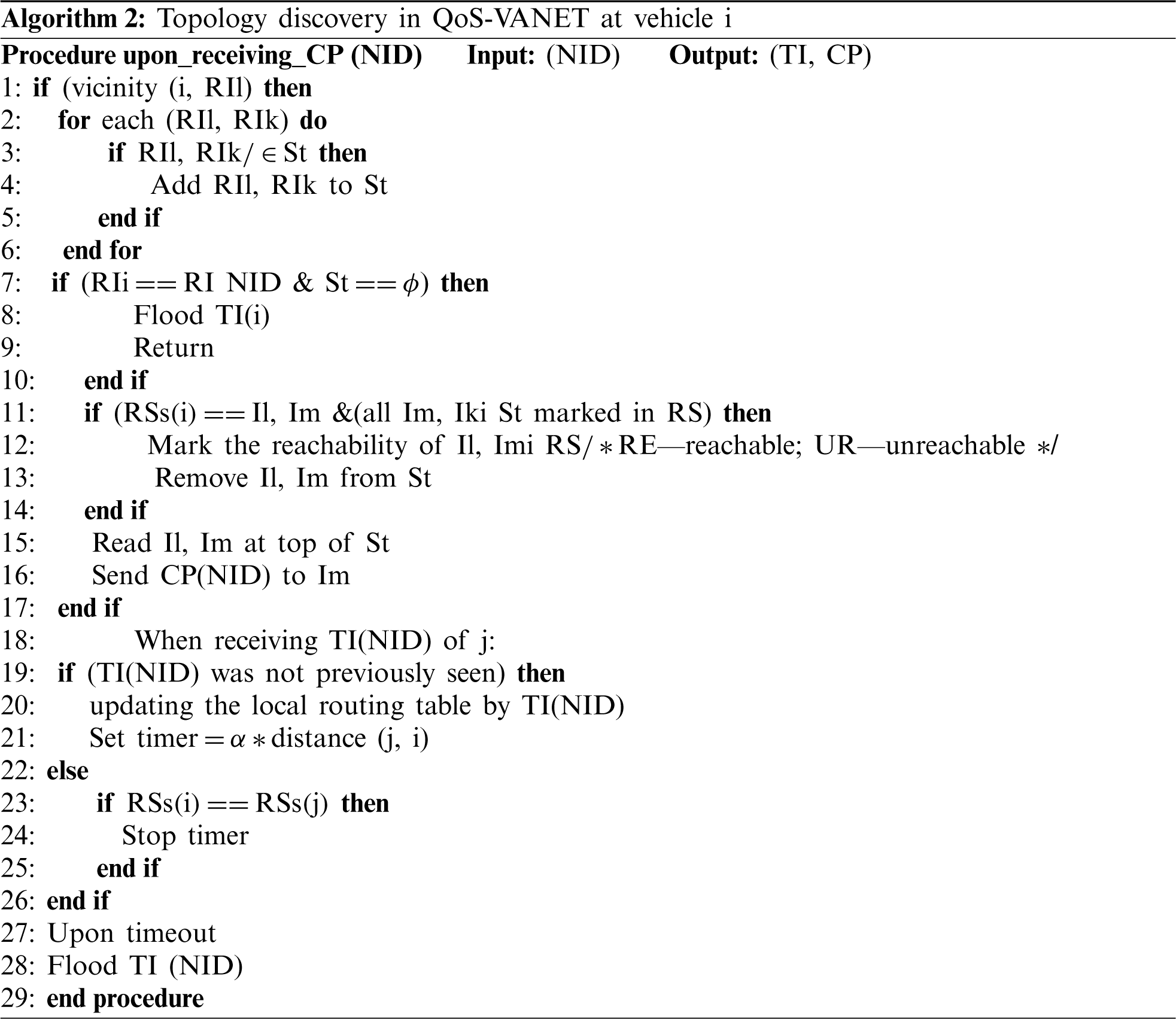
Table 2: Symbols used in Algorithm 2

If a node wants to communicate with another node, the shortest paths to the destination are first calculated. The paths consist of road segments that are marked RE in the RT. The intersections are searched and appended to a CP. The timestamp is also added to the CP that will be used to identify the freshness of the nodes. When the shortest path is calculated, QoS-VANET utilises the concept of loose source forwarding to transmit information and increase the forwarding efficiency.
The packets received by any node update the CP if new route information is available. The route breaks are compensated with geographic routing. The data are forwarded through geographic routing until the data reach the destination or a new route becomes available.
Essential attention is the number of CPs that is required in the VANET. QoS-VANET makes numerous CPs from diverse locations in every periodic update. Such a situation may be desirable for the guarantee of duplication in the occurrence of CP damages or clusters that might normally occur in very unstable VANETs. Certainly, for CH selection, the cluster’s node will obtain the topology change information from the part of VANET from which the CP was initiated, along with information of disconnections. However, vehicles in some other clusters would no longer obtain updates until the cluster is linked. Consequently, CPs should be initiated from different parts of the VANET. The occurrence of several CPs, conversely, raises reliability problems, since a vehicle may receive TI updates from several source nodes.
Throughout VANET operation, the vehicle monitors the packets and marks every single packet as either a non-real-time or real-time packet. If the contents of the packet match the current packet average, it is tagged a non-real-time tag by adding a ZERO bit header at the start. Likewise, in case the contents of the packet do not match the available average, it is tagged as a real-time packet by adding a ONE bit header. The QoS communication computation is given in Algorithm 3.

Before clustering, when the event is triggered, it is sent to the destination by the fastest path. After cluster formation, the data are transferred to the CH. The CH scans each packet header and sends it to the destination through the shortest QoS route if it is ONE. If the packet header is ZERO, the packet will be queued for aggregation and then routed to the destination via either the shortest route or an alternative route, depending on availability.
There are two queues in the CH, namely, NRT and RT queues; the first is for non-real-time data, and the second is for real-time data, as illustrated in Fig. 1. When acquiring packets from the scanning nodes, the CH scans the packets to determine whether they are real-time or non-real-time data. If the received packet contains non-real-time data, it inserts them into the NRT; a packet with real-time data is inserted into the RT queue. Then, the CH routes out the RT queue packets through the shortest QoS route. However, certain aggregation procedures are applied to non-real-time data packets before they are sent to the destination. Only the mean value of the non-real-time packets is then passed to the sink for a time window. The data arriving at the destination may be less redundant. If the arrival rate of real-time packets is lower than the free bandwidth on the shortest QoS route, non-real time packets lend it out, and queued packets from both queues are routed to the sink via this route. However, if the arrival rate of real-time data is higher than the QoS route bandwidth, only real-time data will be sent from the QoS route. Non-real-time data will be randomly forwarded to alternative QoS short links (Algorithm 3).
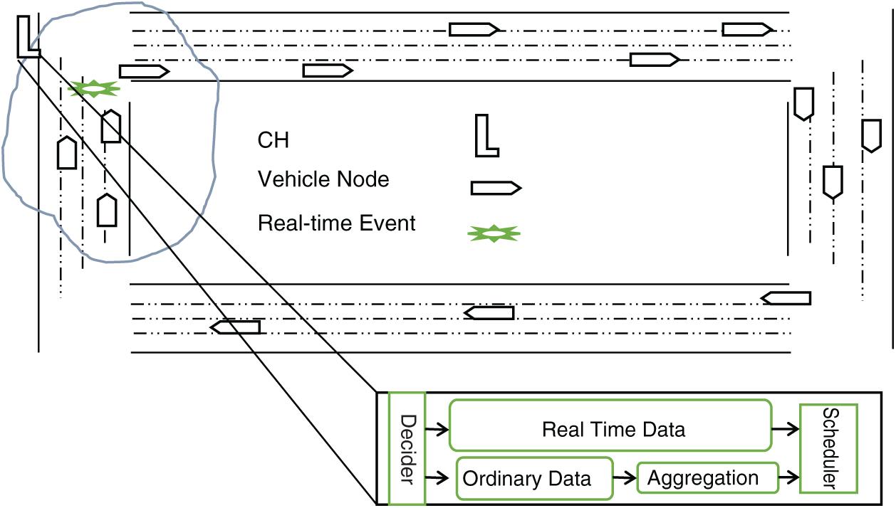
Figure 1: Graphical depiction of cluster and CH
The performance of mobility aware zone-based ant colony optimization routing for VANET (MAZACORNET) [13], CBR [14], passive clustering-aided routing (PASSCAR) [15] and QoS-VANET is evaluated in EstiNet 9.0. The number of vehicles installed in the simulation area is 50. The vehicles are moving at speeds ranging from 1 to 60 km/h. The IEEE communication standard 802.11p (1609.x) is assumed in the experiment. The CSMA/CA medium sharing scheme is adopted in the simulation. The propagation model assumed in the simulation is a two-ray ground model. An omnidirectional antenna is affixed in each vehicle. The vehicles can keep aware of their neighbours’ mobility and have a module for temporarily storing the information and forwarding it to the destination. A constant bit rate input is used to produce traffic and configured for 20 packets p/s. A single test/experiment lasts 50 min. Then, it is repeated up to 100 times and measured by obtaining the average of the test outcomes. In this section, the performance of QoS-VANET, MAZACORNET, CBR and PASSCAR is assessed for different metrics.
Experimental trials are performed, and the number of clusters obtained is averaged for the different tests. The experimentations are conducted for various numbers of vehicles (50 to 450). The number of vehicles is decreased or augmented by 50. Here, the vehicles can move in any direction because the random waypoint mobility model is assumed. The vehicles can communicate with other vehicles in the maximum range of 100 m. Similarly, the vehicles can move at a speed of 60 km/h at the most.
In Fig. 2, the average CHs concerning the VANET size are presented in the form of a line chart. As seen in the figure, the number of clusters increases with the number of vehicles in the VANET, and any increase or decrease in the number of vehicles strongly affects the performance of the clustering algorithm. By matching the arches in the line chart, we perceive that MAZACORNET forms fewer clusters compared with CBR. MAZACORNET performs worse in this situation. The core reason is that MAZACORNET does not consider relative mobility during the clustering. QoS-VANET is the best mechanism among all shown in the graph. In QoS-VANET, the preliminary CH set is nominated based on the node weighting factor, which represents a node’s suitability to become a CH. The distance between CHs is considered during the CH selection process. The closest CHs are reverted, and clusters with few vehicles are combined. Therefore, the mean clusters in QoS-VANET are reduced. These outcomes validate that QoS-VANET does sound as matched to existing/present schemes.
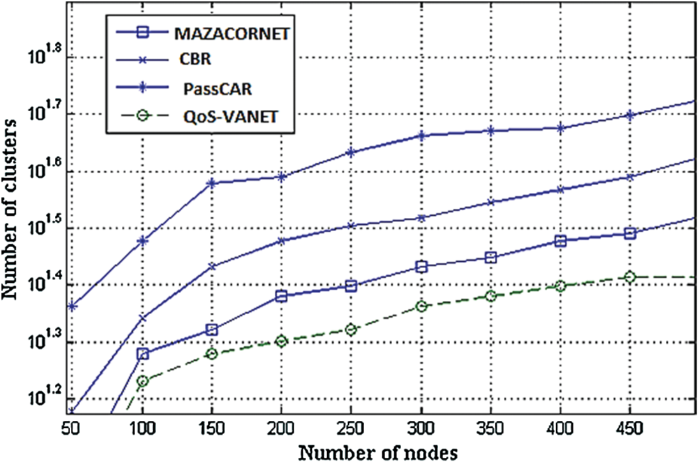
Figure 2: Mean cluster vs. number of vehicles in VANET (TX: 100 m)
As presented in the chart, PASSCAR does well compared with CBR and MAZACORNET. The communication range of the vehicles is set as 200 m, and a sequence of simulation tests is performed in this situation. The outcomes collected during the simulation tests are shown in Fig. 2. The vehicles with high communication ranges considerably decrease the average number of clusters, as revealed in the graph. This is because, with an increase in the radio range of a vehicle, the vehicle can communicate with a large number of other vehicles within range. Therefore, the magnitude of the backbone VANET reduces, since a large number of member vehicles are covered by a small set of CH vehicles. Analogous to the results exposed in Fig. 2, the line chart in Fig. 3 shows that the proposed QoS-VANET outperforms PASSCAR, MAZACORNET and CBR.
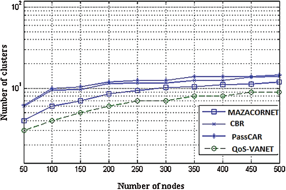
Figure 3: Mean clusters vs. VANET size (TX: 200 m)
The impact of vehicle speed on the duration of clusters is considered in this subsection. The vehicles moving at high speeds strongly impact the lifetime of the clusters and may result in cluster instability. The number of vehicles placed in this simulation experimentation is 50. They can transmit data without the assistance of other vehicles up to 100 m at the most. The vehicles are free to move in any direction at a maximum speed of 80 km/h. The outcomes acquired throughout the distinct tests are averaged. The cluster lifetime is in seconds. In Fig. 4, the mean lifetime of the clusters in the VANET is demonstrated. The proposed QoS-VANET cluster formation scheme performs better than the state-of-the-art clustering schemes in the VANET for cluster stability, as presented in Fig. 4. Constant mobility characteristics were assumed in some recent work on CPs in VANETs. Thus, the conduct of vehicles throughout their travel cannot be projected in these algorithms in the long run.
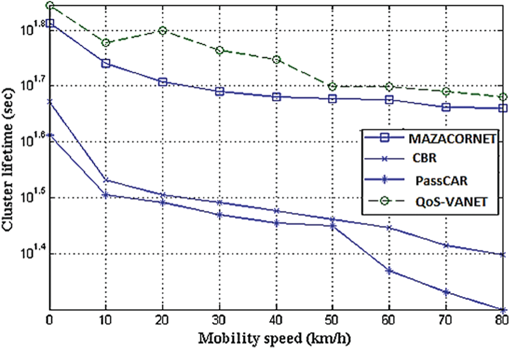
Figure 4: Vehicle speed vs. cluster lifetime (TX range: 100 m)
In the proposed QoS-VANET, the vehicles have a prolonged relationship with their CHs because the vehicles’ relative mobility is considered during CH selection. The relatively steady vehicles are the most appropriate vehicles for fulfilling the primary role of CHs. The arches shown in Fig. 4 express that CBR forms clusters for a shorter period. The efficiency of MAZACORNET is higher than that of CBR but second only to PASSCAR. The unsteady clusters are designed once CBR is executed. CBR does not assume the relative mobility of vehicles during the formation of clusters; therefore, the steadiness factor is compromised. The broadcast range of every vehicle is fixed to 200 m at the most in the following simulation test, and the outcomes are presented in Fig. 5. The other factors are the same as those in Fig. 4. The life of the VANETs concerning different broadcast ranges is elaborated.
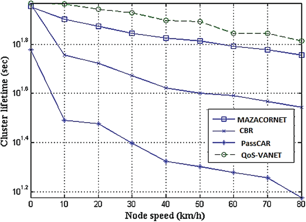
Figure 5: Cluster duration and node speed with transmission range of 200 m
Increasing the broadcast range may increase the cluster lifetime in all the algorithms. The vehicles stay within the radio range of the other vehicles for a long time; hence, stable clusters are achieved. This is a simple way to increase the broadcast range of the vehicles to prolong a cluster’s lifetime. The proposed QoS-VANET performs well compared with PASSCAR, MAZACORNET and CBR, as depicted in Fig. 5.
Numerous simulation experiments are executed to assess the impact of the range of vehicle transmissions and their speed on the re-affiliation rate. This rate shows vehicle behaviour in reaction to topology changes; this is the rate at which a vehicle leaves a CH and joins an alternative CH in a specified period. The outcomes collected throughout these simulation tests are illustrated in the following paragraph. Vehicles can join a new cluster for two reasons. The first is when a CH leaves their part as a CH because of certain reasons, such as mobility, transmission range and energy exhaustion. Second, the vehicles themselves may leave their locations and may travel to different positions. Thus, such vehicles may not be linked to the original CHs any longer. With fast VANETs, the re-affiliation rate may grow because the vehicles may leave their CHs rapidly and could become affiliated with another CH.
The line chart depicted in Fig. 6 demonstrates the mean re-affiliation rate of vehicles with various movement patterns. At this point, the vehicle speed significantly influences the re-affiliation rate. With an increase in vehicle speed, the re-affiliation rate becomes high in all the involved clustering schemes. Remarkably, QoS-VANET has the lowermost re-affiliation rate among all the clustering schemes, as presented in Fig. 5. The outcomes discussed in the preceding section indicate that the proposed QoS-VANET scheme may outperform the existing schemes. The re-affiliation rate of QoS-VANET is low because the relative speed of vehicles and various other significant factors are taken into account throughout the cluster setup. The re-affiliation rate may be further reduced if the clustering algorithm forms long life clusters. The relative speed of vehicles is considered in CBR; therefore, it performs well next to QoS-VANET. The member vehicles of a cluster in CBR stay linked with their CHs for a long period, and their re-affiliation rate may be lower. PASSCAR performs poorer in terms of the re-affiliation rate amongst all the considered algorithms. The mobility of the communicating units is not considered in this algorithm when selecting the CH, resulting in unstable clusters in the network.

Figure 6: Re-affiliation rate for variable speed
Fig. 7 illustrates the findings of experimental tests with different wireless ranges of communicating units. During these tests, the communicating units travel at a constant speed of 40 km/h. The wireless transmission range of the communicating units varies from 20 to 200 m. The range of transmission is incremented by 30 in every test. According to the findings in Fig. 6, the transmission range affects all the simulated schemes, including the suggested QoS-VANET. With a high transmission range of communicating units, a broader range is covered, and the likelihood of one device leaving the current cluster and joining a different cluster is small. QoS-VANET performs satisfactorily across the different transmission ranges relative to the other schemes. The proposed scheme takes into account the direction and speed of the communicating devices in the clustering procedure, thus obtaining stable clusters.
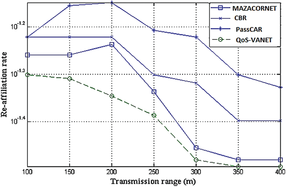
Figure 7: Transmission range and re-affiliation rate
During clustering, packets exchanged among communicating nodes in the network in a unit of time are referred to as control message overhead. All clustering schemes require certain packets to be sent to the clusters in the VANET. Here, the control overhead of both the considered protocols (CBR, PASSCAR and MAZACORNET) and QoS-VANET is described. Fifty communication devices are used in the network in the series of tests. The RWP model is adopted for mobility. The speed of the communicating devices varies from 10 to 80 km/h in each experiment. The transmission range is configured to be 200 m. Figs. 8 and 9 illustrate the average of the obtained results in the chain of experimental simulations. CBR, for example, performs poorly in terms of control message overhead. The graph illustrates that the line at the CBR is within the high range. The effects of increasing the mobility speed can be observed for all the simulated schemes. The control overhead rises with the mobility of communication devices. It is possible to minimise the control effort by setting the transmission range of the communicating units to the maximum. In comparison with devices with low transmission modules, communication units with a high transmission range consume more energy. Cluster life can be extended at high transmission ranges, but the total network life can shorten. The proposed QoS-VANET takes into account the residual power of communicating units when forming clusters.

Figure 8: Control overhead and speed of nodes with transmission range of 100 m

Figure 9: Control overhead and speed of nodes with transmission range of 200 m
In QoS-VANET, a node’s eligibility is verified before its selection as a CH, and it acts as a CH for a sustained period, thus reducing the overhead for control messages. Key factors reducing control overhead are long-lasting CHs, consideration of mobility and selection of high-power nodes.
Figs. 8 and 9 show that the proposed QoS-VANET algorithm requires the least control overhead, whereas CBR requires more. QoS-VANET works well because it considers the relative mobility of communicating devices during clustering. As a result, clusters can become stable across the network. After stable clustering, the rate of re-affiliation will eventually decrease. Likewise, if the re-affiliation is minimal, the overhead of the control messages will decrease as the procedure of re-clustering is performed less frequently. Thus, the proposed QoS-VANET algorithm excels in comparison with the other considered algorithms.
Quantification for load balancing is computed here to show one cluster’s balance. The converse of the variance of the cluster’s cardinality defines the load balancing factor (LBF). Hence,

CHn denotes the total number of CHs, xi denotes the cardinality for cluster i, and  denotes the average number of CH neighbours (which corresponds to the total number of vehicles in the network). The load distribution is improved for high equation values. Ideally, the equation value tends towards infinity for a balanced network. Fig. 10 illustrates MAZACORNET, PASSCAR, CBR and the proposed QoS-VANET LBFs. The equation value is computed for a 50-node network with different ranges of transmission. The figure illustrates that QoS-VANET provides balanced clusters better than the other schemes.
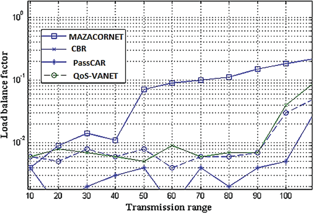
Figure 10: Transmission range and load balancing (10–100 m)
Results are plotted in Fig. 11. The computing effort is measured for networks of different sizes. Certain tests are performed for different ranges of transmissions. Communication units are set to a 50 km/h speed. At high values of the transmission range, the neighbourhood configurations are long and thus lead to slower execution. The same effect can be observed in the case where the communication devices are incremented at the same ratio and the neighbourhood contains a significant number of communicating devices. Fig. 12 shows the experimental results for a set of routine data source reference points at (30; 30), (170; 170; 170), (170; 30), (30; 170), (50, 150) and (150, 50). The delay is lower for real-time and unusual data in HRRRR than in RRR, as indicated in the graph. In this scenario, since the routine data sources’ reference points are at a greater distance from the sink, the travel latency is greater compared with the average latency.

Figure 11: Instruction’s number and scalability (transmission range: 100 m)
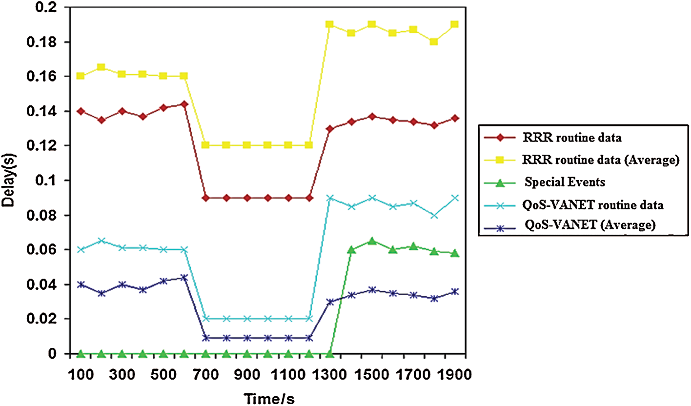
Figure 12: Travel delay for set of routine data source reference points
During this step, we examine a bigger network that is used in an area of  m; the node density is 500, and the sink resides in the middle. This network includes a packet drop of
  :1. If a packet is on the move for more than a specified period inside the network, it will be trashed. There is a timeout feature in each origin node to resend the packet unless it receives confirmation from the recipient. Following the timeout and an added delay M, the origin node resends the packets. In this simulation, both timeout and delays are regarded as constraints of
  and
and  . The propagation delays of the packets with
  :02 s,
  :2,
:2,  pkt/s and
  pkt/s are illustrated in Fig. 13. The delay is very long for the short timeout period, and it rises as it exceeds the optimum timeout length. The propagation delay of routinely sent data packets is longer for packets that have ONE bit as their header.

Figure 13:  vs. propagation delay with
  pkt/s,
  ,
,  pkt/s,
  ,
, 
In this paper, we propose QoS-VANET, which identifies data packets and tags them as real-time or non-real-time packets. Honeybee optimisation is used to select the optimised number of CHs. Each CH examines the packets and prioritises the RT packets for QoS routing and non-real-time packets for routine cluster-based routing. In this way, the non-delay-tolerant data can be transferred to the destination with minimal latency while keeping the advantages of clustering.
Acknowledgement: This research was supported by Taif University Researchers Supporting Project Number (TURSP-2020/231), Taif University, Taif, Saudi Arabia.
Funding Statement: The authors received no specific funding for this study.
Conflicts of Interest: The authors declare that they have no conflicts of interest to report regarding the present study.
1. S. Al-Sultan, M. M. Al-Doori, A. H. Al-Bayatti and H. Zedan. (2014). “A comprehensive survey on vehicular ad hoc network,” Journal of Network and Computer Applications, vol. 37, no. 1, pp. 380–392. [Google Scholar]
2. Y. Agarwal, K. Jain and O. Karabasoglu. (2018). “Smart vehicle monitoring and assistance using cloud computing in vehicular ad hoc networks,” International Journal of Transportation Science and Technology, vol. 7, no. 1, pp. 60–73. [Google Scholar]
3. D. Xuting, J. Wei, D. Tian, J. Zhou, H. Xia et al. (2019). , “Adaptive handover decision inspired by biological mechanism in vehicle ad-hoc networks,” Computers, Materials & Continua, vol. 61, no. 3, pp. 1117–1128. [Google Scholar]
4. M. Belghachi and D. Naouel. (2019). “An efficient greedy traffic aware routing scheme for internet of vehicles,” Computers, Materials & Continua, vol. 60, no. 3, pp. 959–972. [Google Scholar]
5. F. Cunha, L. Villas, A. Boukerche, G. Maia, A. Viana et al. (2016). , “Data communication in VANETs: Protocols, applications and challenges,” Ad Hoc Networks, vol. 44, no. 1, pp. 90–103. [Google Scholar]
6. F. Khan, R. Wattenhofer, Y. Zhang and A. Zollinger. (2003). “Geometric ad-hoc routing: Of theory and practice,” in Proc. of the Twenty-Second Annual Symposium on Principles of Distributed Computing, Boton, Massachusetts, USA, pp. 63–72. [Google Scholar]
7. B. Karp and H. T. Kung. (2000). “GPSR: Greedy perimeter stateless routing for wireless networks,” in Proc. of the 6th Annual Int. Conf. on Mobile Computing and Networking, Boston, Massachusetts, USA, pp. 243–254. [Google Scholar]
8. P. Bose, P. Morin, I. Stojmenović and J. Urrutia. (2001). “Routing with guaranteed delivery in ad hoc wireless networks,” Wireless Networks, vol. 7, no. 6, pp. 609–616. [Google Scholar]
9. M. Ahmad, A. Hameed, A. A. Ikram and I. Wahid. (2019). “State-of-the-art clustering schemes in mobile ad hoc networks: Objectives, challenges, and future directions,” IEEE Access, vol. 7, no. 1, pp. 17067–17081. [Google Scholar]
10. M. Ahmad, A. A. Ikram, R. Lela, I. Wahid and R. Ulla. (2017). “Honey bee algorithm-based efficient cluster formation and optimization scheme in mobile ad hoc networks,” International Journal of Distributed Sensor Networks, vol. 13, no. 6, pp. 1550147717716815. [Google Scholar]
11. A. Masood, A. A. Ikram, I. Wahid, F. Ullah, A. Ahmad et al. (2020). , “Optimized clustering in vehicular ad hoc networks based on honey bee and genetic algorithm for internet of things,” Peer-to-Peer Networking and Applications, vol. 13, no. 2, pp. 532–547. [Google Scholar]
12. A. Masood, A. Hameed, F. Ullah, I. Wahid, S. U. Rehman et al. (2018). , “A bio-inspired clustering in mobile adhoc networks for internet of things based on honey bee and genetic algorithm,” Journal of Ambient Intelligence and Humanized Computing, vol. 2018, no. 1, pp. 1–15. [Google Scholar]
13. H. Rana, P. Thulasiraman and R. K. Thulasiram. (2013). “MAZACORNET: Mobility aware zone based ant colony optimization routing for VANET,” IEEE Congress on Evolutionary Computation, Cancun, vol. 2013, no. 1, pp. 2948–2955. [Google Scholar]
14. M. Alowish, Y. Takano, Y. Shiraishi and M. Morii. (2017). “Performance evaluation of a cluster based routing protocol for VANETs,” Journal of Communications, vol. 12, no. 2, pp. 137–144. [Google Scholar]
15. S. S. Wang and Y. S. Lin. (2013). “PassCAR: A passive clustering aided routing protocol for vehicular ad hoc networks,” Computer Communications, vol. 36, no. 2, pp. 170–179. [Google Scholar]
 | This work is licensed under a Creative Commons Attribution 4.0 International License, which permits unrestricted use, distribution, and reproduction in any medium, provided the original work is properly cited. |