DOI:10.32604/cmc.2021.015272
| Computers, Materials & Continua DOI:10.32604/cmc.2021.015272 | |
| Article |
Green5G: Enhancing Capacity and Coverage in Device-to-Device Communication
1Department of Cyber Security, Air University, Islamabad, Pakistan
2Department of Computer Science, Kinnaird College for Women, Lahore, 54000, Pakistan.
3Department of Computer Science, College of Computer Science and Engineering, Taibah University, Madinah, Saudi Arabia
*Corresponding Author: Abdul Rehman Javed. Email: abdulrehman.cs@au.edu.pk
Received: 13 November 2020; Accepted: 12 December 2020
Abstract: With the popularity of green computing and the huge usage of networks, there is an acute need for expansion of the 5G network. 5G is used where energy efficiency is the highest priority, and it can play a pinnacle role in helping every industry to hit sustainability. While in the 5G network, conventional performance guides, such as network capacity and coverage are still major issues and need improvements. Device to Device communication (D2D) communication technology plays an important role to improve the capacity and coverage of 5G technology using different techniques. The issue of energy utilization in the IoT based system is a significant exploration center. Energy optimization in D2D communication is an important point. We need to resolve this issue for increasing system performance. Green IoT speaks to the issue of lessening energy utilization of IoT gadgets which accomplishes a supportable climate for IoT systems. In this paper, we improve the capacity and coverage of 5G technology using Multiple Inputs Multiple Outputs (MU-MIMO). MU-MIMO increases the capacity of 5G in D2D communication. We also present all the problems faced by 5G technology and proposed architecture to enhance system performance.
Keywords: Green computing; 5G; energy efficiency; resource optimization; device to device communication; multiple input multiple output
Green computing is the ecologically mindful utilization of PCs and related assets such practices incorporate the execution of energy-effective focal preparing units, workers, and peripherals just as diminished asset utilization and legitimate removal of electronic waste. The main purpose of green computing is to minimize the use of toxic and hazardous materials and improve energy efficiency. Presenting D2D correspondence in a cell organization will improve the general information rate, energy utilization, and range use while offering new types of assistance. The future of telecommunication is represented by the term 5G. As compared to recent trends in current cellular technology, it is an advancement that brought radical changes in radio interference [1]. 5G technology is fast, easy, and reliable as compared to present cellular technology [2]. Predictably, 5G will result in high rates of data transfer that would go further, more than 10 gigabytes per second [3].
D2D communication is known to be one of the basic solutions for the next generation 5G networks to compact with these problems. D2D communication plays an important role in direct communication between devices (devices may be mobile phones or vehicles) without any help from the Base station in cellular networks. With early studies, D2D communication discloses some advantages for developing spectrum effectiveness, message interruption, and energy depletion. However, it still faces some limitations, such as security concerns, flexibility managing, and hand-off. Fig. 1 shows the basic architecture of D2D communication. The investigation community is now participating in adopting D2D communication for the next generation.
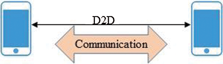
Figure 1: Device to device communication
The network designer always focuses on system performance in terms of efficiency and coverage. The Spectral Efficiency (SE) gives a proportion of the number of pieces of data that can be moved to the served users for a given transmission capacity while noise ratio “Signal-to-Interference Ratio (SINR)” is used to obtain coverage performance. D2D communication did not gain much importance in the earlier generations i.e., 1G, 2G, 3G, or 4G. However, in 5G it plays an important role in Cellular communications. So 5G is one of the emerging technologies which allow devices for direct transmission with the help of D2D communication. It increases the reliability of connection among the devices, system capacity, and improves the spectral productivity, which may lead to lower latency. With the help of D2D communication, two devices can communicate with each other without any intermediate device i.e., Base Station. Neighboring devices can communicate easily with each other through a link due to a smaller distance. When the distance between devices is smaller it automatically enhances the power of a system in cellular communication. It leads to improvements in Throughput, energy efficiency, delay, and can handle the traffic effectively. So, we can say that is a reliable technique for communication.
Energy optimization plays an important role in Device-to-Device Communication (D2D) [4–6]. The network traffic is reduced by placing the BS in between the devices and it conserves the energy-inefficient manner [7]. Another challenge faced by 5G is MU-MIMO. MU-MIMO contains multiple antennas on the sending and receiving side to develop the capacity and coverage area for D2D communication. As we know it is a wireless network that allows multiple users on sending and receiving of more than one data instantaneously above the same radio channel [8]. It uses the radio path image to enhance performance. MIMO which stands for multiple input multiple output technology has evolved over the years since the Single User Mode (SU-MIMO) launch, launched with the 802.11n wireless standard a decade ago. Supported MU-MIMO was implemented in Wave 2 devices by the 802.11ac (Wi-Fi 5) standard. Now we see even more enhancements to MU-MIMO with the 802.11ax (Wi-Fi 6) standard.
MU-MIMO is used to enhance the capacity of D2D communication. It consists of the following characteristics, which provokes the researchers to use in capacity and coverage enhancement [9].
• MU-MIMO can be consisting of 1-way or 2-way communication
• MIMO technology is complimented by Orthogonal Frequency-Division Multiple Access (OFDMA)
• 802.11ax network protocol supports MU-MIMO
• MU-MIMO can work in both bandwidths 2.4 and 5 Ghz
• For direct signaling, beamforming is used
• Multiple users with multiple antennas are interrelated
• Regarding the legacy point of view, it is very beneficial
• Any type of channel width can be supported by MU-MIMO
• Through signal processing security of the network also increase
Network coverage and capacity are the major issues in the 5G network. During device, to device communication, this problem occurs mostly. While in D2D the in-band communication uses certified frequency sources and out-bands uses un-certified frequency sources. Device relaying with operator control link (DROC) required low coverage area and this type of device cannot connect directly with the base station. This paper focuses on discussing the challenges, designs, and future research directions of 5G cellular networks to enhance the capacity and coverage using Mu-MIMO.
This paper focuses on 5G technology with D2Dcommunication for enhancement of capacity and coverage. We design a system model to enhance the overall performance after increasing the nu of antennas using MU-MMIO. While using MU-MIMO with SNR our performance is increased gradually with 4, 6, and 8 antennas. After placing these antennas in different places everyone can easily use the web browsers and audio or video streaming due to increasing signals strength.
The rest of the paper is organized as follows. Section 2 presents the background of emerging technologies. Section 3 provides a comparison between MU-MIMO and SU-MIMO. Section 4 provides the proposed methodology and Section 5 presents the simulation and results. Finally, Section 6 concludes the work.
2 Background of Emerging Technologies
G. Marconi unveils that the growth and expansion of wireless start from the pathway of the latest wireless communications that communicate the letter S adjacent to 3 km distance with aid of electromagnetic wave [10]. It exhibits the developing generations of wireless technologies in terms of coverage, movement, spectral productivity, and data speed. The coverage, movement, spectral productivity, and data speed increases gradually. Bluetooth, WiMAX, and Wi-Fi are using the uncertified spectrum but on the other hand, a certified spectrum is used by all generations.
First-generation of the emerging system is grounded on the technique of equivalent pointers as it was used in circuit switching. It was formulated not for data but voice communication. This technology works on radio towers where the voice was transmitted and use the frequency 150 MHz, with the help of Frequency Division Multiple Access (FDMA) but this technique does not meet all the requirements due to low capacity and unreliable handoff. It consists of the following difficulties (e.g., lower voice links, no security, and undesirable snooping of the third party) were increased due to radio towers [11].
The 2nd generation was introduced in the late 1990s. Numerical technology was used in 2nd generation mobile telephone systems. In this system, first of all, Global Systems for Mobile communications (GSM) was introduced. It was used for voice communication and having a data speed of up to 64 kbps. Vital eminent technologies were GSM, Code Division Multiple Access (CDMA), and IS-95. The integration of ascertain antennas of MIMO considered as the hypo-potential element for the communication between various applications. [11,12].
This generation was recognized in 2000 as having a data speed 2 Mbps. It was founded by Internet Protocol to combine high-speed mobiles. This technology is more expensive than 2G [11]. The data rate is improved in 3G up to 30 Mbps. Due to the increase in bandwidth, it fulfills all the requirements of a good system. We can contact each other and exchanged information in real-time. Now a days 3G technology is still used in the world providing 15–20 MHz bandwidth [12].
The speed of wireless technology is also called 4G. It can transmit data due to the conceptual framework and support rates of up to 100 Mbps. Due to high speed, it covers a large area [13,14]. 4G cannot support the switching technologies but it is based on Internet Protocol communications using IP technology. The technique used for the multiple antennas and its transmission is a basic pillar, which helps to enhance the capacity and area coverage of devices. It is very easy to send a massive quantity of data from one device to another device using 4G. Due to its wide range, 4G is a broadband network having broader bandwidth. 4G usually comes from 2G and 3G. Video chat is one of the important examples used in 4G [14–16].
5G is not yet a dominant technology in the world. Computer scientists are trying to develop 5G technology to meet all the requirements. All the network is responsible to handle the mobility [17], its terminal responsibility to choose the several access points in a network. This type of choice is based on an open intellectual middleware in mobile phones. An orthogonal beam is used for every mobile station which removed the antennas- based scheme and uses one or many base stations. In this way, the capacity of the system is enhanced [18]. A clue to move towards 5G is based on present ideas. It is normally supposed that 5G cellular networks must address six challenges that are not efficiently talked about by 4G i.e., greater capacity, greater data speed, inferior End to End dormancy, huge device connectivity, reduced cost, and reliable Quality of Skill provisioning [19]. Recently presented IEEE 802.11ac, 802.11ad, and 802.11af standards are very helpful. It also acts as building blocks in the road towards 5G. The Y-shaped antenna in the rotated form is scrutinized by using the Finite-Integration-Technique (FIT) engaged in the software of Computer-Simulation-Technology (CST), which may be designed for the future of 5G technologies and its applications. [20–23].
2.6 Device to Device Communication
The fourth-generation base station is included in all kinds of communication. There is no direct communication among two devices under the certified band. In the emerging era of technology Device-to-device communication is the key factor for the enhancement in the advanced network coverage [24]. 5G is the certified band for direct communication of two devices. This phenomenon of direct communication is known asD2D communication. As any base station is not involved in D2D, so it will reduce the traffic from the base station and will transport an unrestricted separation to the base station. Such traffic will increase the capacity of the system. Furthermore, D2D is characterized into four categories:
2.6.1 Device Relaying with Operator Controlled Link Establishment (DR-OC)
A user can easily access the base station by transmitting the signals through other devices in this DROC. Such a form of communication requires a minimum coverage area where devices are not joined to the base station directly such as cell ends. The operator connects with the transmitting devices so that it can have complete or partial control on D2D. The architecture of DR-OC is shown in Fig. 2 [25].
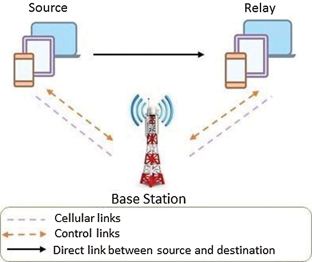
Figure 2: D2D link having device relaying and operator control
2.6.2 Direct D2D Communication with Operator Controlled Link Establishment (DC-OC)
This type deals with exchanging; sending and receiving information and data of devices transactions without the involvement of the base station. On the other hand, the operator is responsible for the process of link formation. the operator is a partial controller in this type of D2D communication. The architecture of DC-OC is shown in Fig. 3 [25].
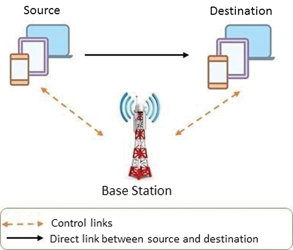
Figure 3: D2D link having a direct link and operator control
2.6.3 Device Relaying with Device Controlled Link Establishment (DR-DC)
The operator does not take the information of the link or transmission of data in this type. Entirely all engagements like distribution of resources, device managing, device detection are done by the devices. Consequently, sending and receiving devices are accountable for all these processes. Though, a third device named relaying device is involved in the exchange of information concerning communicating devices. We use this relaying device whenever there is a greater distance among communicating devices. The architecture of DR-DC is shown in Fig. 4 [25].
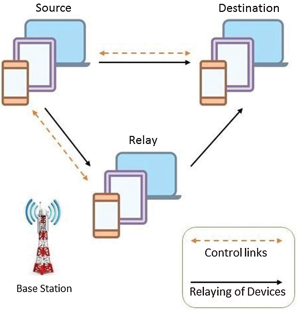
Figure 4: D2D link having device relaying and control
2.6.4 Direct D2D Communication with Device Controlled Link Establishment (DC-DC)
In this type, neither operator nor a relaying device is used for communication between devices. During the process of communication, the obligation of transmission of data, power drinking, organization interference, resource allocation, security, and whatever the condition is built on those devices, that are communicating to each other. The architecture of DC–DC is shown in Fig. 5 [25]. This is a power-saving method of D2D communication. Therefore, those users who are connected try to use assets in a good fashion, by keeping them to ensure not to disturb each other.
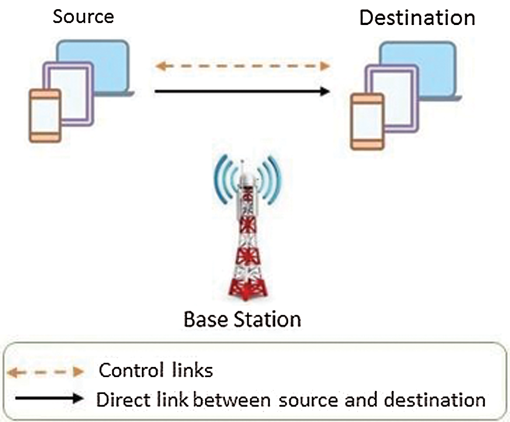
Figure 5: D2D link having a direct link and device control
2.6.5 Application of 5G D2D Communication
As we know that cellular communications have evolved from 1G to 5G cellular networks. D2D communication plays an important role to enhance the overall system performance using 5G technology. There are the following applications of 5G D2D communication.
• Increasing Spectral Efficiency in D2D communication two devices can communicate with each other without using any intermediate device e.g., router in a network. In this way, hop must be a rise, which results in reusing the resources [26]. So, we can say that in cellular networks D2D communication is helpful in resource reuse gain. Due to recourse reuse gain and hop gain, the spectral efficiency must be increased.
• Emergency Communication D2D communication helps in a natural disaster like an earthquake and communication network infrastructure. When network infrastructure is spoiled, a wireless network must be set between the terminals. These problems can be solved using D2D communication in a network.
• IoT Enhancement While developing the device communication it is important to develop a broad network that consists of different types of terminals. The typical example of D2D communication is Vehicle to Vehicle (V2V). According to developing technologies in V2V, two vehicles can communicate with each other and apart from each other at a specific distance. Because in case of any emergency an alert is generated to inform the driver making the speed slow. So, when vehicles use D2D communication drivers can reduce the risk of incident, which leads to IoT enhancement.
In this work, we use an MU-MIMO technique to enhance the capacity and network coverage in device-to-device communication. Green cellular communication is used to reserve energy using different techniques. When a BS is placed in between the devices it consumed energy due to its processing and many other factors. Due to growing awareness trends of energy optimization, an effective approach must be needed to save the energy resources in D2D communications. BS is placed to reduce the network traffic and load by providing good quality signal strength to mobile users.
3 Comparison Between MU-MIMO and SU-MIMO
According to our proposed model, we propose that MU-MIMO enhances the capacity and coverage in 5G technology for D2D communication. Here we give s brief comparison with the help of Tab. 1 that illustrates the difference between MU-MIMO and SU-MIMO.
Table 1: Comparison between MU and SU-MIMO
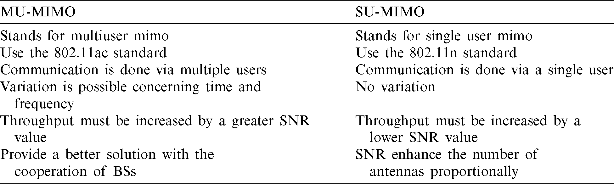
It also proves that MU-MIMO is s best technology due to multiple antennas on the transmitter and receiver side, instead of SU-MIMO. So, we can say that it helps to improve the data rate quality, bandwidth, Throughput, capacity, and coverage area with the help of 5G technology. Thanks to the multiple users in MU-MIMO playing an important role in multiple user communication on the transmitter and receiver side.
MU-MIMO innovation additionally enables different users to have similar system assets, at the same time. Multi-User MIMO or “MU-MIMO” enables messages for various users to travel safely along similar information pipelines, at that point be arranged to singular users, when the information transfer at their mobile phones [27,28]. Providing multiple users with the same data transmission speed increases capacity and helps to utilize resources in a better way. With a better capacity, helps multiple users to download and access the network at an equal and efficient rate. Likewise, networks can progressively switch between serving one or various clients. At the point when a single client is served, regularly the beam is more straightforward, and power is focused efficiently. Although, when multiple users are connected the beam spread at a wider distance in different directions [29]. In our proposed model MU-MIMO technique is used, which helps us to improve the coverage and capacity of the whole network during D2D communication.
We applied MU-MIMO on D2D, V2V with a relaying operator. All the MU- MIMOs are connected to one single base station. By using Base Station all the users are connected to the internet and store data on the cloud, and from cloud data stored and fetched from the data centers or servers. For all sorts of communication links: we applied MU-MIMO, which helps multiple users to connect and share information or data [30]. It helps a lot to maximize the capacity and coverage of the network to everyone. As earlier, MIMO is already considered a useful wireless communication way. But from now on, in our study, we use MU-MIMO which radically changes the usage of mobile devices. The proposed models (Fig. 6) describe how multiple users communicate with each other by using multiple antennas.
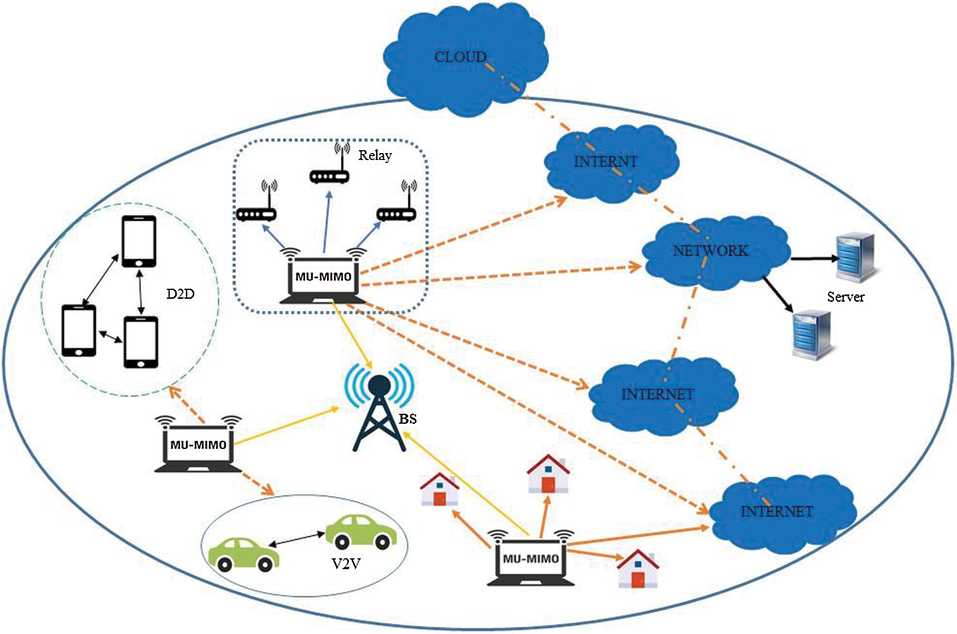
Figure 6: Proposed model
For the working of MIMO, the transmitter (access point) and receiver (user) each one has multiple antennas sequences. For example, on the access point and on the user side one single stream used to send data and similarly one single stream to receive likewise, that supports one-bit ( ) connectivity: Based on this example two-bit stream will support (
 ) connectivity in both directions, and a three-bit stream (
 ) will also support connectivity in both directions. Any mobile device that supports one or more streams will work with that device that supports less connectivity and continue due to which its performance is reduced. Fig. 7 illustrates the working of MU-MIMO with more than one user [19]. When we use the MU-MIMO the system, it contains multiple antennas at the transmitting and receiving side, which helps us to improve the capacity of the overall system and increase the coverage area. By adding the multiple antennas, the sender shared with some handling algorithms of the signals, while on the receiver side capacity and diversity performance shows. The MU-MIMO channel is a wireless connection between N and M antennas (where N is the transmitter and M is the receiver). The co-efficient of MU-MIMO is represented in the form of NM elements. The multiple antennas (n or M) could probably connect to any single modem or it may connect to different users. whereas H represents the Capacity of the Channel. For an MU-MIMO channel with N and M antennas, we take H as the size of channel matrix
  , in Eq. (1):


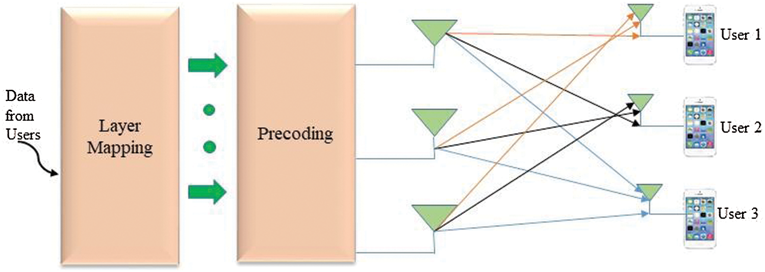
Figure 7: Working of MU-MIMO
In the above Eq. (2) ‘det’ means determinant, where lM means (transmitter receiver)
  identity matrix and HHH means Matrix transpose conjugate. While in Eq. (3) numbers of NM antennas are very important; the capacity for the Rayleigh channel propagates proportionally to M is the expected value of the function.

In the above Eq. 3, Capacity increases much faster in MU-MIMO systems than simple MIMO thanks to a large number of antennas case. In the next section, we discuss the simulation and results of the proposed model. The capacity of the  system is given in Eq. (4). Here
  on the transmitter side and
  on the receiver side respectively. The expression is given as follows.

The capacity of the  system is given in Eq. (5). Here
  on the transmitter side and
  on the receiver side respectively. The expression is given as follows.

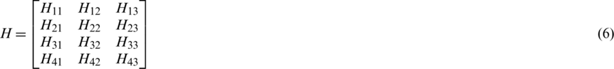
The capacity of the  system is given below in Eq. (6),
  antennas on the transmitter side, and
  on the receiver side. While h, i, j are the complex numbers. The alphabet i is taken as nu of rows and j is taken as nu of columns.
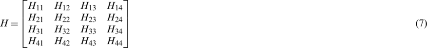
While increasing the number of antennas on both transmitter and receiver side, let  and
and  then we can see that capacity increase linearly to time. The following expression is made in this case. The Eq. (7) indicates that there are four received signals. Here H is co-channel interference.
The total nu of transmitting antennas is given in Eq. (8) below. Here NR represents the total receiving antennas. In these Equations u and v represent the number of rows and columns.

The total nu of transmitting antennas is given in Eq. (9) below. Here NT represents the total transmitting antennas.

Both Equations represent the total number of transmitting and receiving antennas, which helps out to enhance the overall system capacity using MU-MIMO.
We choose SNR Algorithm for MU-MIMO to enrich the capacity of channels and selected antennas. We choose the MATLAB Platform to practically implement the SNR algorithm. As a result, the following plots are generated. These plots show the capacity of the channel, which is selected. The following flowchart (Fig. 8) is the SNR Algorithm. First of all, SNR or session value is calculated and then the session is selected with the mean value. In this way, new sessions are created one by one. Once the subcarrier value is assigned to the current session then the system removes this session from the list.
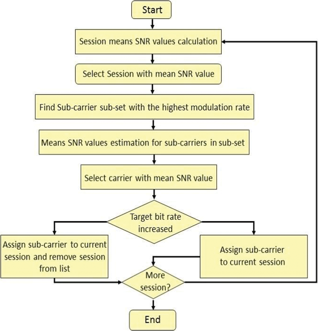
Figure 8: Flowchart for the working of SNR Algorithm
The capacity of the channel increases theoretically when one antenna has been used to send and receive signals in the system with multiple users. It also represents the working of the SNR Algorithm step by step and ensures that the performance of the system must be increased using SNR. Fig. 8 represents the working of the SNR algorithm; it works step by step in an efficient manner. Fig. 9 helps to illustrate that capacity of selected antennas increases linearly due to the MU-MIMO technique. This graph is generated by running the SNR Algorithm in MATLAB and shows that the capacity of selected antennas increased linearly. We can say that our performance is better instead of SU-MIMO.
Figure 9: Capacity of selected antennas
Fig. 10 helps to illustrate the plot for the selected antenna by using the SNR algorithm the capacity increases linearly, whereas the system has an equal number of antennas to send and receive signals. In this graph 4, users on the transmitter and receiver side are communicating with each other. Here we can observe that capacity is increased gradually after using 4 antennas. In Fig. 10, the capacity of the 4th antenna is 22 bits/s/Hz.
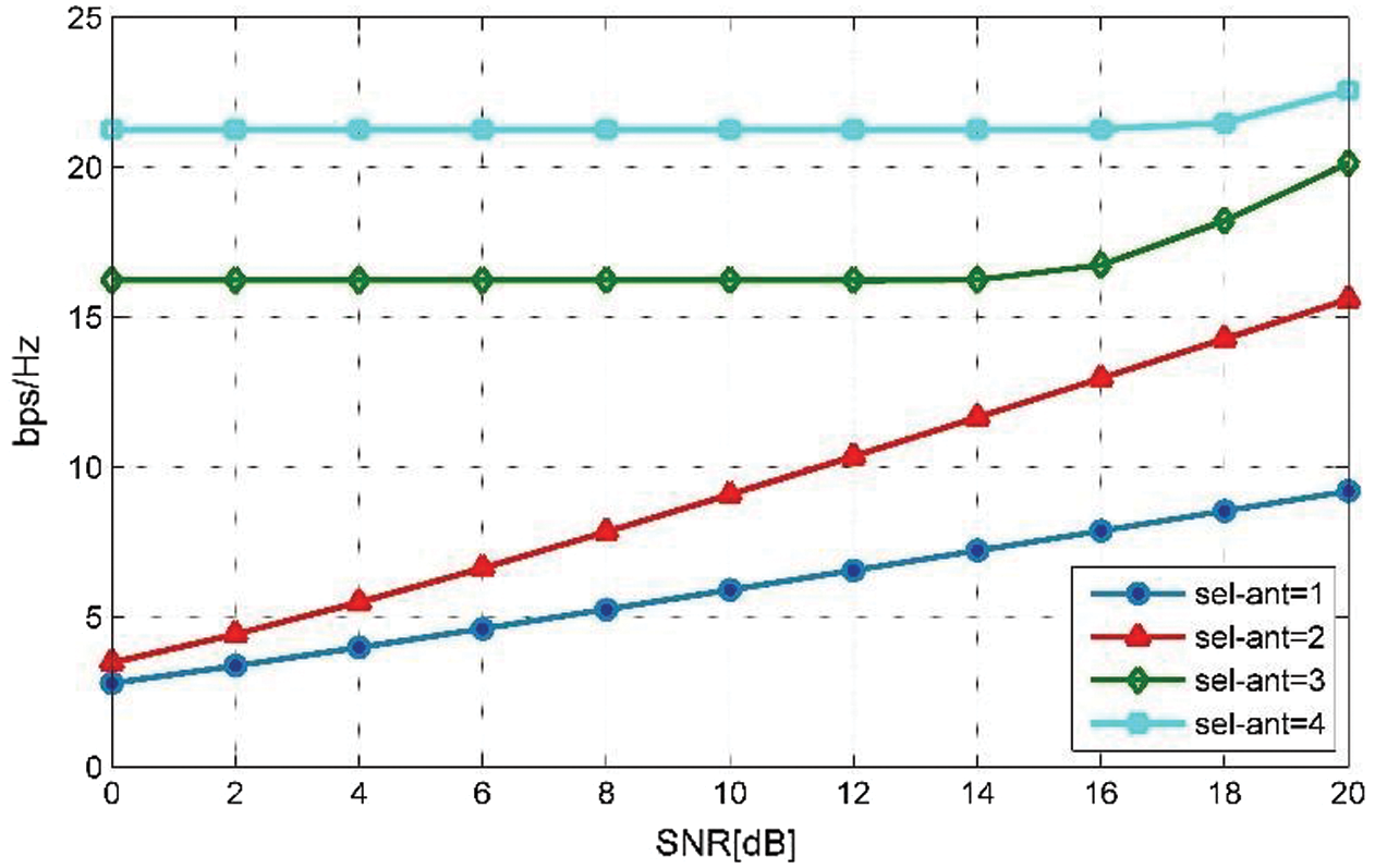
Figure 10: Plot for selected antennas
Fig. 11 illustrates the capacity of MU-MIMO with the SNR algorithm using 6 antennas. Here capacity increases linearly while increasing the nu of antennas. Similarly, while increasing the nu of antennas according to Fig. 12 then the capacity of the first four antennas is the same and makes variations in 5 and 6.
a) On the transmitter side  and
and  capacity increase to 25 bits/s/Hz
b) On the receiver side  and
and  capacity increase to 28 bits/s/Hz

Figure 11: Plot for the capacity of MU-MIMO with SNR using 6 antennas
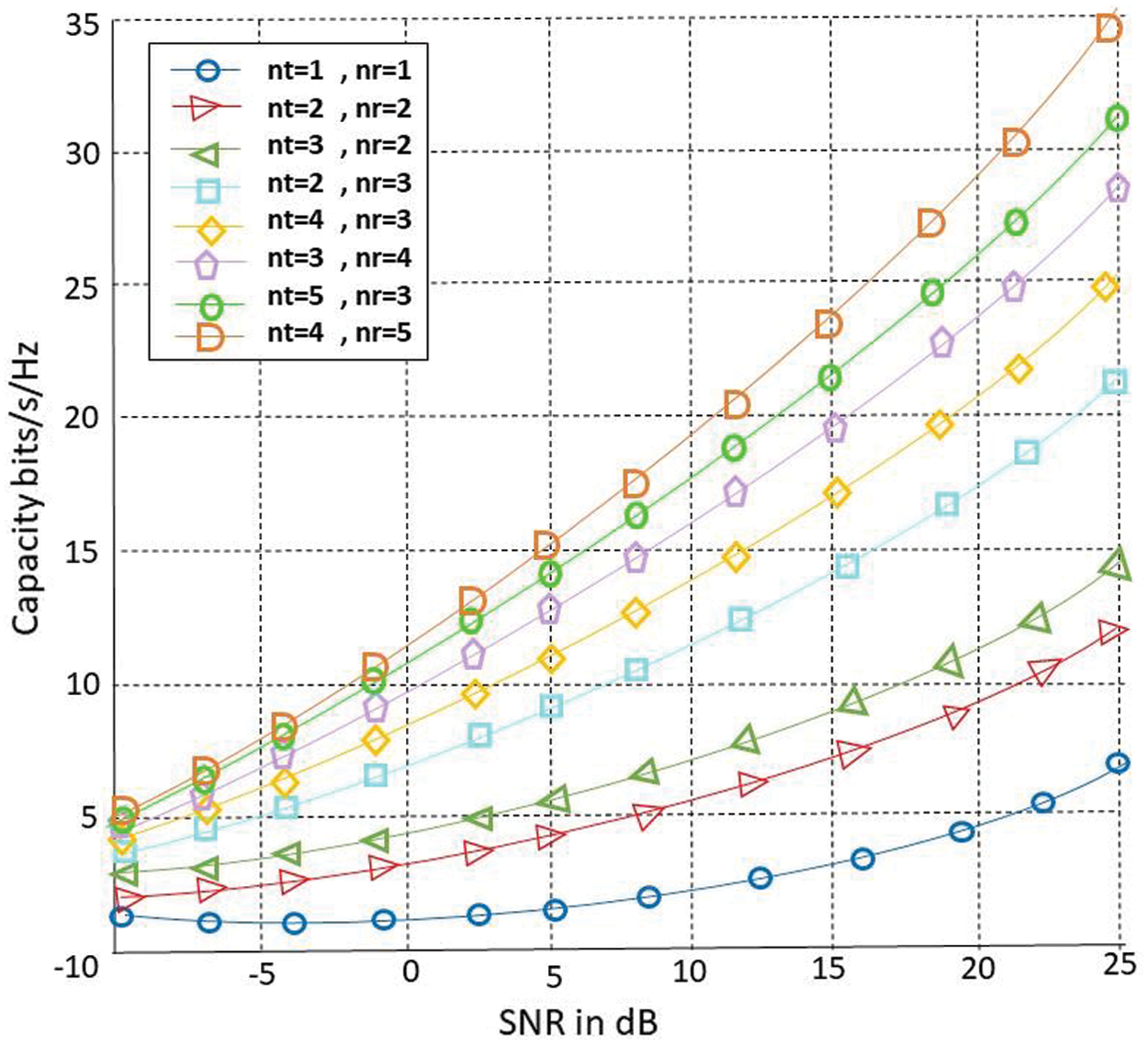
Figure 12: plot for the capacity of MU-MIMO with SNR using 8 antennas
In Fig. 11, as we have used 6 antennas with SNR for increasing the capacity and coverage. So, we can observe that our performance is increased gradually after increasing the number of antennas. Here the total capacity of the 6th antenna is almost 29 bits/s/Hz.
Fig. 12 illustrates the capacity plot of MU-MIMO using 8 antennas. Capacity must be increase linearly with increasing nu of antennas on both transmitter and receiver side. In this scenario, we have used 8 antennas and make variations according to Figs. 12 and 13. Here capacity increase when we increase the nu of antennas on both transmitter and receiver side. The capacity of the first six antennas is the same as Fig. 13 and increase while using antenna 7 and 8.
a) On the transmitter side  and
and  the capacity is increased to 32 bits/s/Hz
b) On the transmitter side  and
and  , the capacity is increased to 35 bits/s/Hz
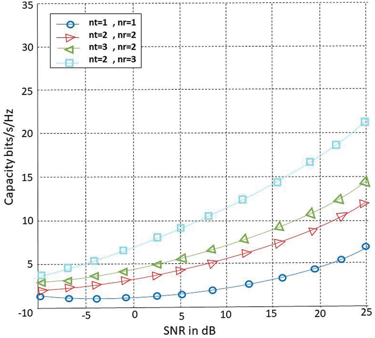
Figure 13: plot for the capacity of SU-MIMO with SNR using 4 antennas
In Fig. 12, we have used 8 antennas to enhance the capacity and coverage of our proposed system, we can easily find the difference after increasing the number of antennas. Here the total capacity of the 8th antenna is 35 bits/s/Hz, which is increased linearly. We can say that our proposed system performed well.
Fig. 13 illustrates the capacity of SU-MIMO with the SNR Algorithm. We have got different averages using  MIMO,
MIMO,  MIMO,
MIMO,  MIMO, and
  MIMO respectively. All the users offer a different average plot, in this plot capacity increase linearly. Fig. 11 illustrates the capacity of SU-MIMO with the SNR Algorithm. Here NT represents the nu of transmit antennas and NR represents the nu of receiving antennas. The capacity increased linearly with the increasing nu of antennas as shown in Fig. 11. Here we use 4 antennas, the capacity increases linearly while increasing the nu of antennas. All the antennas provide different capacity plots:
a) In the graph, we use only one transmitter and receiver, capacity is almost 8 bits/s/Hz,
b) While using  and
and  capacity increase to 12 bits/s/Hz.
c) When increasing the nu of antennas on both sides  ,
,  the capacity is 15 bits/s/Hz
d) While using  ,
,  the capacity is 22 bits/s/Hz.
Fig. 14 is another scenario which represents that how capacity enhances in MU-MIMO technology instead of SU-MIMO. Thanks to the multiple antennas in the MU-MIMO technique that plays an important role to enhance the capacity. SU-MIMO gives a higher throughput with lower SNR, while MU-MIMO gives higher throughput with greater SNR. Due to higher the SNR more cost is required in MU-MIMO because multiple users are sharing data on both transmitter and receiver sides. So, when we applied MU-MIMO for all types of communication capacity must be enhanced due to multiple users on both sides, and the coverage area is also increased in this technique. In Fig. 14 difference is clear between SU-MIMO and MU-MIMO, which leads to our best system performance.
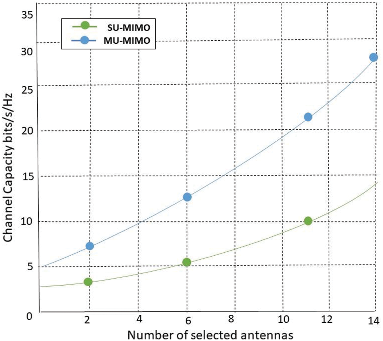
Figure 14: Capacity of SU-MIMO and MU-MIMO using SNR
In our proposed model all the data is fetched from the Cloud which facilitates us to establish a connection and share the information. Hence, we can conclude that MU-MIMO enhances the capacity and coverage area of a network with the help of SNR.
Reduced energy consumption is achieved by D2D communication where energy is conserved in cellular communication by green computing (placing BS among the devices). By using different techniques, D2D communication plays an important role in improving the capacity and coverage of 5G technology. In this research, we try to overcome the challenge of the capacity and coverage faced by 5G technology using MU-MIMO. By implementing the MU-MIMO technique, it increases the capacity of 5G technology in D2D communication. One of the major challenges in 5G technology is Capacity and Coverage. Implementing the MU-MIMO with SNR Algorithm helps to overcome the issue and discussed a brief comparison between MU-MIMO and SU-MIMO. Multiple antennas in MU-MIMO helps to enhance capacity and coverage. As, MIMO naturally has a spatial range, which increases the power of the system by removing weaknesses. But on the other hand, there are still some challenges exits like cost estimation and security, etc., which will surely be considered as future work.
Acknowledgement: The authors extend their heartfelt thanks to the Department of Computer Science, College of Computer Science and Engineering, Taibah University Madinah, Saudi Arabia.
Funding Statement: The authors extend their heartfelt thanks to the Department of Computer Science, College of Computer Science and Engineering, Taibah University Madinah, Saudi Arabia.
Conflicts of Interest: The authors share no conflict of interest.
1. R. N. Prieto. (2016). “10th annual cisco visual networking index (VNI) mobile forecast projects 70 percent of the global population will be mobile users,” . Available Online: https://newsroom.cisco.com/press-release-content [Accessed 20-11-2020]. [Google Scholar]
2. R. Davies. (2016). 5G network technology: Putting Europe at the leading edge. EPRS, European Parliamentary Members’ Research Service, . Available Online: https://www.europarl.europa.eu/RegData/etudes/BRIE/2016/573892/EPRS_BRI(2016)573892_EN.pdf [Accessed 20-11-2020]. [Google Scholar]
3. M. A. Panhwar, M. SullemanMemon, S. Saddar and U. Rajput. (2017). “5g future technology: Research challenges for an emerging wireless network,” International Journal of Computer Science and Network Security, vol. 17, no. 12, pp. 201–206. [Google Scholar]
4. P. K. R. Maddikunta, T. R. Gadekallu, R. Kaluri, G. Srivastava, R. M. Parizi et al. (2020). , “Green communication in IoT networks using a hybrid optimization algorithm,” Computer Communications, vol. 159, pp. 97–107. [Google Scholar]
5. M. Mittal and S. Kumar. (2019). “Performance evaluation of LEACH protocol based on data clustering algorithms,” in Proc. of 2nd Int. Conf. on Communication, Computing, and Networking, Singapore, Springer, pp. 135–144. [Google Scholar]
6. A. R. Javed, M. Usman, S. U. Rehman, M. U. Khan and M. S. Haghighi. (2020). “Anomaly detection in automated vehicles using multistage attention-based convolutional neural network,” IEEE Transactions on Intelligent Transportation Systems. [Google Scholar]
7. C. Iwendi, Z. Jalil, A. R. Javed, T. R. Gadekallu, R. Kaluri et al. (2020). , “KeySplitWatermark: Zero watermarking algorithm for software protection against cyber-attacks,” IEEE Access, vol. 8, pp. 72650–72660. [Google Scholar]
8. M. Mittal, C. Iwendi, S. Khan and A. R. Javed. (2020). “Analysis of security and energy efficiency for shortest route discovery in low-energy adaptive clustering hierarchy protocol using Levenberg–Marquardt neural network and gated recurrent unit for an intrusion detection system,” Transactions on Emerging Telecommunications Technologies, vol. 117, no. 1, pp. 56. [Google Scholar]
9. M. I. Zahoor, Z. Dou, S. B. H. Shah, U. I. Khan, S. Ayub et al. (2020). , “Pilot decontamination using asynchronous fractional pilot scheduling in massive MIMO systems,” Sensors, vol. 20, no. 21, p. 6213. [Google Scholar]
10. F. Hu and C. Xiaojun. (2010). Wireless sensor networks: Principles and practice. Boca Raton: CRC Press. [Google Scholar]
11. S. I. Naqvi, N. Hussain, A. Iqbal, M. Rehman and M. Forsat. (2020). “Integrated LTE and millimeter-wave 5G MIMO antenna system for 4G/5G wireless terminals,” Sensors, vol. 20, no. 14, p. 3926. [Google Scholar]
12. C. O. Iwendi. (2011). “Power consumption trade-off analysis in an OFDM communication chain,” in IEEE Africon’11, Livingstone, Zambia, IEEE. [Google Scholar]
13. P. Semov, P. Koleva, K. Tonchev, V. Poulkov and T. Cooklev. (2020). “Evolution of mobile networks and C-RAN on the road beyond 5G,” in 43rd Int. Conf. on Telecommunications and Signal Processing, Milan, Italy, IEEE, pp. 392–398. [Google Scholar]
14. B. Furht and S. A. Ahson. (2016). Long term evolution: 3GPP LTE radio and cellular technology. Boca Raton: CRC Press. [Google Scholar]
15. H. M. Douglas. (2020). Multiple antenna techniques. In: Key 5G Physical Layer Technologies. Cham: Springer, pp. 169–196. [Google Scholar]
16. S. Sesia, I. Toufik and M. Baker. (2011). LTE-the UMTS long term evolution: From theory to practice. Hoboken, New Jersey, USA: John Wiley & Sons. [Google Scholar]
17. P. K. Agyapong, M. Iwamura, D. Staehle, W. Kiess and A. Benjebbour. (2014). “Design considerations for a 5g network architecture,” IEEE Communications Magazine, vol. 52, no. 11, pp. 65–75. [Google Scholar]
18. C. Wang, F. Haider, X. Gao, X. You, Y. Yang et al. (2014). , “Cellular architecture and key technologies for 5g wireless communication networks,” IEEE Communications Magazine, vol. 52, no. 2, pp. 122–130. [Google Scholar]
19. P. Popovski. (2013). “Scenarios, requirements and kpis for 5G mobile and wireless system,” METIS Deliverable D, vol. 1, pp. 1. [Google Scholar]
20. J. Khan, D. A. Sehrai, M. Ahmad Khan, H. A. Khan, S. Ahmad et al. (2019). , “Design and performance comparison of rotated y-shaped antenna using different metamaterial surfaces for 5G mobile devices,” Computers Materials & Continua, vol. 60, no. 2, pp. 409–420. [Google Scholar]
21. E. H. Ong, J. Kneckt, O. Alanen, Z. Chang, T. Huovine et al. (2011). , “IEEE 802.11 ac: Enhancements for very high throughput WLANs,” in IEEE 22nd Int. Symp. on Personal, Indoor and Mobile Radio Communications, Toronto, ON, Canada, pp. 849–853. [Google Scholar]
22. E. Perahia and M. X. Gong. (2011). “Gigabit wireless lans: An overview of IEEE 802.11 ac and 802.11 ad,” ACM SIGMOBILE Mobile Computing and Communications Review, vol. 15, no. 3, pp. 23–33. [Google Scholar]
23. B. Flores, R. E. Guerra, E. W. Knightly, P. Ecclesine and S. Pandey. (2013). “IEEE 802.11 af: A standard for tv white space spectrum sharing,” IEEE Communications Magazine, vol. 51, no. 10, pp. 92–100. [Google Scholar]
24. H. H. Hussein, H. A. Elsayed and S. M. El-kader. (2019). “Intensive benchmarking of D2D communication over 5G cellular networks: Prototype, integrated features, challenges and main applications,” Wireless Networks, vol. 26, no. 5, pp. 1–20. [Google Scholar]
25. P. Gandotra and R. K. Jha. (2016). “Device-to-device communication in cellular networks: A survey,” Journal of Network and Computer Applications, vol. 71, pp. 99–117. [Google Scholar]
26. J. H. Anajemba, Y. Tang, J. A. Ansere and C. Iwendi. (2018). “Performance analysis of D2D energy-efficient IoT networks with relay-assisted underlying technique,” in IECON 2018-44th Annual Conf. of the IEEE Industrial Electronics Society, Washington, DC, USA, IEEE. [Google Scholar]
27. M. I. Zahoor, Z. Dou, S. B. H. Shah, U. I. Khan, S. Ayub et al. (2020). , “Pilot decontamination using asynchronous fractional pilot scheduling in massive MIMO Systems,” Sensors, vol. 6213, no. 21, pp. 6213. [Google Scholar]
28. P. K. Reddy Maddikunta, G. Srivastava, T. Reddy Gadekallu, N. Deepa and P. Boopathy. (2020). “Predictive model for battery life in IoT networks,” IET Intelligent Transport Systems, vol. 14, no. 11, pp. 1388–1395. [Google Scholar]
29. R. Vinayakumar, M. Alazab, S. Srinivasan, Q. Pham, S. K. Padannayil et al. (2020). , “A visualized botnet detection system based deep learning for the Internet of Things networks of smart cities,” IEEE Transactions on Industry Applications, vol. 56, no. 4, pp. 4436–4456. [Google Scholar]
30. S. P. RM, S. Bhattacharya, P. K. R. Maddikunta, S. R. K. Somayaji, K. Lakshmanna et al. (2020). , “Load balancing of energy cloud using wind-driven and firefly algorithms in the internet of everything,” Journal of Parallel and Distributed Computing, vol. 142, pp. 16–26. [Google Scholar]
 | This work is licensed under a Creative Commons Attribution 4.0 International License, which permits unrestricted use, distribution, and reproduction in any medium, provided the original work is properly cited. |