DOI:10.32604/cmc.2021.013896
| Computers, Materials & Continua DOI:10.32604/cmc.2021.013896 | |
| Article |
An Improved iBAT-COOP Protocol for Cooperative Diversity in FANETs
1Quaid-i-Azam University, Islamabad, Pakistan
2Iqra National University, Peshawar, Pakistan
3Network and Communication Technology Lab, Center for Cyber Security, UKM, Bangi, Malaysia
4Department of Information Technology, College of Computer, Qassim University, Buraydah, Saudi Arabia
5Department of Electrical Engineering, Onaizah College of Engineering & Information Technology, Al-Qassim, Saudi Arabia
*Corresponding Author: Sheroz Khan. Email: cnar32.sheroz@gmail.com
Received: 30 August 2020; Accepted: 19 November 2020
Abstract: Flying ad hoc networks (FANETs) present a challenging environment due to the dynamic and highly mobile nature of the network. Dynamic network topology and uncertain node mobility structure of FANETs do not aim to consider only one path transmission. Several different techniques are adopted to address the issues arising in FANETs, from game theory to clustering to channel estimation and other statistical schemes. These approaches mostly employ traditional concepts for problem solutions. One of the novel approaches that provide simpler solutions to more complex problems is to use biologically inspired schemes. Several Nature-inspired schemes address cooperation and alliance which can be used to ensure connectivity among network nodes. One such species that resembles the dynamicity of FANETs are Bats. In this paper, the biologically inspired metaheuristic technique of the BAT Algorithm is proposed to present a routing protocol called iBAT-COOP (Improved BAT Algorithm using Cooperation technique). We opt for the design implementation of the natural posture of bats to handle the necessary flying requirements. Moreover, we envision the concept of cooperative diversity using multiple relays and present an iBAT-COOP routing protocol for FANETs. This paper employs cooperation for an optimal route selection and reflects on distance, Signal to Noise Ratio (SNR), and link conditions to an efficient level to deal with FANET’s routing. By way of simulations, the performance of iBAT-COOP protocol outperforms BAT-FANET protocol and reduces packet loss ratio, end-to-end delay, and transmission loss by 81%, 21%, and 82% respectively. Furthermore, the average link duration is improved by 25% compared to the BAT-FANET protocol.
Keywords: Routing protocols; UAVs; FANETs; iBATCOOP; BATCOOP
FANET is a subclass of VANETs which can govern the autonomous movements of Unmanned Aerial Vehicles (UAVs). The complexities of FANETs do not aim to maintain wide-range communication between the UAVs. It is easy to establish star topology when dealing with a single UAV. It can be a center of the star but has limitations when extending the coverage area. Signal strength may extend the area but an increase in power causes interference and unreliable communication for long-distance communication. Applications of FANETs are forest-fire detection, search and rescue operations, traffic and urban monitoring, patrolling and reconnaissance, agricultural management, and relaying network [1]. Topology based routing approach in the dynamic routing of FANETs can improve the network efficiency in terms of throughput, end-to-end delay and network load [2]. Similarly, FANETs adaptive routing protocol based on a fuzzy system [3] can validate and improve the protocols for dynamic topology network and estimate the Quality of Service (QoS) and Quality of Experience (QoE). UAVs communication issues involve limited transmission range, high speed with uncertain movement and energy drain.
Communication is crucial when dealing with high mobility nodes and to sustain cooperation and collaboration between UAVs. Not all multi-UAVs systems do not have to form FANETs [4]. Communication between UAVs in an ad hoc network is realized by the aid of cooperation between them. However, if communication between UAVs fully relies on UAV-to-infrastructure links then it cannot be classified as a FANET. Further, architecture of communication for infrastructure-based networks restricts the capabilities of FANETs. Communication between UAVs in ad hoc manner can resolve issues of infrastructure based networks. General scenario of FANETs deployment is depicted in Fig. 1.
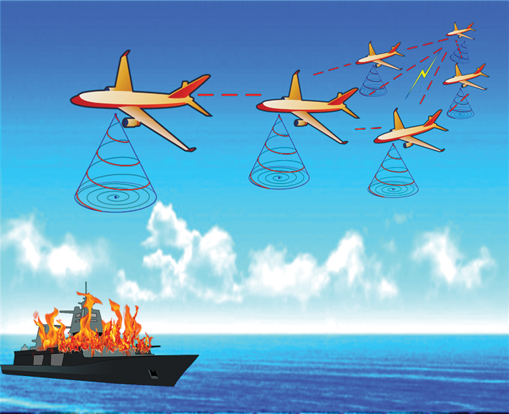
Figure 1: A general scenario of FANETs deployment
1.1 Types of Fanets Communications
FANETs communications can take place in the following possible ways: namely,which consider multiple UAVs to ensure long-range, environment resilient communication, and Line-of-sight (LoS) propagation. These UAVs may be in the same plane or different depending on varying altitudes as shown in Fig. 2. The FANET inter-plane communication considers the communication of UAVs when they lie within the same plane whereas FANET intra-plane communication extends the altitude and UAVs can communicate with others through available mediums such as high altitude, low altitude, and terrestrial medium [5].
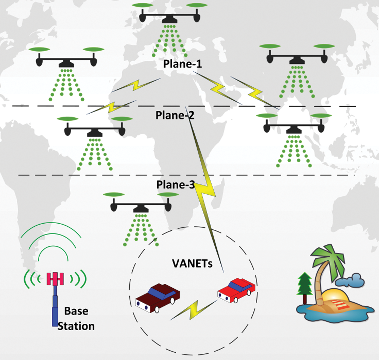
Figure 2: Types of FANETs communication
FANET ground station communication extends the coverage area from air to ground. UAVs are unable to connect directly from high altitude medium to the ground station because the strength of these tiny devices is very low, for example, limited energy, limited communication range, and uncertain mobility. High range and advanced technology sensor nodes are required to establish this communication. FANET-VANET communication is also a type of air-to-ground communication and comprises of ground vehicles and flying UAVs. The mobility degree of ground vehicles is slow as compared to the UAVs but technological advancement and research studies enable the establishment of network and transfer information.
FANETs deal with many challenging issues such as limited bandwidth, limited energy capacity, high latency, and frequent node disconnections. Even though great literature is found on different challenges in FANETs but in future perspectives there are still critical issues that need attention to be investigated.
• The topology of FANETs is more dynamic than typical ad hoc networks (MANETs and VANETs). As a result, the designs of existing routing protocols (QMAA [6], D-LAR [7], DABFS [8], PDMAC [9], DSR [10], GreeAODV [11], LD-OLSR [12], TA-AOMDV [13], SIR [14] and Improved GPSR [15]) partly fail in tracking network topology changes. These protocols do not aim to undertake directly for FANETs due to high-speed mobility of nodes and rapidly changing positions. Further, unpredictable aerial navigation, environment, and fluctuated trajectory-related tasks no longer meet the demands of autonomy and do not lead the traditional built-in-rules protocols.
• Rapid advancements of wireless communication in FANETs organize the self-governing flight of UAVs and comfort the UAV-to-UAV communication. This type of network is different from traditional ad hoc networks in terms of connection and delivery of data. Multiple UAV systems achieve effective real-time communication during flight missions but it is necessary to set strategy for FANETs challenges.
• The networking architecture of FANETs involves multiple UAVs which could work as relay nodes and hence wireless ad hoc network among UAVs is established. These relay nodes work together to forward the data until it reaches the destination. According to the communication type, there are two segments involved in communication “ground or satellite segment” and “aero segment” [16]. In the former segment, few UAVs can directly communicate with ground stations or through satellites and known as UAV-to-infrastructure communication while in the latter segment UAVs do not have any direct links with the ground station and can connect and popularly known as UAV-to-UAV communication.
Cooperative diversity can be adopted efficiently when multiple antennas are not possible. More worthwhile, this can be feasible for special indicators of frequency, time, and spatial diversity which cannot afford multiple antennas. In the context of cooperation, nodes can share packets with their neighbors and establish a group to transmit the data to the destination. Fig. 3 shows a concept of cooperation where physical-layer diversity combine is performed by the destination node to combine multiple signals. Most of the ideas realized that traditional broadcast techniques create a promising future but cooperation has its potential to reform betterment. A concept of cooperation employs the broadcast characteristic of wireless channels which can forward the packets to the destination using nodes as a relay.
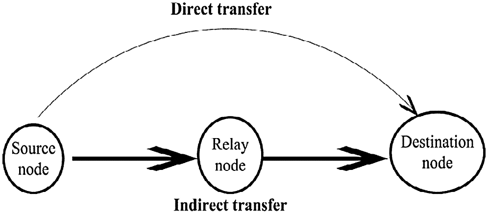
Figure 3: Concept of cooperation
The major contributions of this paper are as follow:
• Information Transfer is ensure the quality and reliability under dynamic network FANETs conditions.
• Measurement of the optimal track of the packets, which are received at the destination node using relay.
• Proposed an enhanced iBAT-COOP protocol has improved evaluation of existing objectives, besides packet loss ratio and average link duration deployment of ‘n’ relay is achieved.
• iBAT-COOP can detail the features of rapid deployment and frequent movement of FANETs’ nodes.
• Enabled first computation and then path selection employing either direct or indirect path transfer.
Multi UAVs play an important role to choose the networking architecture for best performance. Different networking architectures are proposed and emerged in [17]. The basic one is centralized link communication which is established between the UAV and a single Ground Station (GS), which may result in ground congestion.
In [18], three common characteristics of time-dependent mobility models of VANETs are considered. At first, vehicles on the road follow each other. Secondly, memory-based vehicles are considered in which new speed and direction are dependent on their last movement. Thirdly, the authors have considered that the vehicles within its given range can move at any speed. So these circumstances have provided the smooth movement, minimizes the acceleration and changes of direction. Authors in [19] have studied the polynomial-time algorithm along with successive Mobile Base Station (MBS) placement. At the start, sequential placements of MBSs have been deployed for uncovered bounded area Ground Terminals (GTs). The main aim of this research was to reduce the number of MBSs which have been placed to provide wireless coverage. Instead of relays, this research study preferred the MBSs which required additional power to extend the coverage area. Although the minimum number of MBSs placement is achieved, traffic congestion and network overhead increase as the MBSs decrease. In [20], a technique of controlling the UAVs movements has been investigated in a specific area. This technique employed the UAVs to improve the strength of the signal to achieve better communication and transmission rate.
The applications of Optimized Link State Routing (OLSR) and its extension Predictive OLSR (P-OLSR) are proposed in [21] respectively. The idea of a multi-point relay is used in OLSR scheme to bring down the network flooding and traffic while P-OLSR found the route and it is based on expected transmission count and speed. Although transmission of frequent control packets can be seen in OLSR, it required more usage and storage complexity. The major problem of OLSR is maintaining information about unused routes, having the risk of resource wastages. In [22], authors combined an Omnidirectional and directional transmission and investigated the adjustment of dynamic angle for FANETs routing. The characteristic of this routing is a hybrid use of unicasting and geo casting routing. Therefore, an increase in path lifetime is achieved in terms of packet transmission and route setup rate.
In [23], the authors aimed to achieve communication between UAV and ground vehicles to support the mobile infrastructure in disaster situations. Fast-moving UAVs and comparatively slow-moving vehicles did establish communication in this research work by adopting a terrestrial medium. There are multiple factors involved in this medium to disrupt the signal and reduce the communication efficiency. Interference is one of the major factors to be caused by this disaster. In [24], UAV is performed as a relay to the ground users to support the UAVs capacity and their distribution in 2-D and 3-D space. A hybrid technique of wireless communication is investigated in [25] which details the feature of the high data transmission rate of 802.11 and low-power consumption of 802.15.1. This improved the network performance in terms of delay and throughput and reduced the communication cost. Recently, the role of UAV and FANETs architecture utilizes the applications and features of ad hoc communication for dynamic networks [26], but it lacks from the concept of cooperation ensuring the reliability in FANETs communication.
FANETs is complex and challenging to enable nodes to arrange packet forwarding for sharing information. Due to similarity with MANETs, researchers are studying the applicability of MANETs routing in FANETs by adopting intelligent modification. However, different requirements such as mobility pattern, deployment technique, and requirements of QoS need investigation [27]. Consequently, the limitations of FANETs routing permit us to develop new routing protocols in the form of IBANET, ensuring cooperative diversity for efficient network performance. Moreover, this improves SNR over traditional Single Input Single Output (SISO) because relays may help to overcome the congestion and network overhead issues. Further, Cooperation can save transmit power, increase the data rate, and extend the communication range to improve SNR.
Various bat-inspired algorithms can be setup by using echolocation characteristics of micro-bats. For ease of access, the following assumptions have been considered [28]:
a) Owing to the echolocation characteristic of bats, all of them can sense distance, the difference between food/prey, and also sense the availability of surrounding obstacles.
b) Flying of the bat in target searching is random having velocity ‘v’ position ‘p’, fixed frequency ‘fmin’ varying wavelength ‘ ’ and loudness ‘l’. Naturally, the proximity of prey can be computed from the automatic adjustment of frequency or wavelength. This can also be measured from the emission of ultrasonic waves and pulse emission rate
  .
.
c) The loudness of bat may vary in different manners but let us consider that it varies from a large (positive) l0 to a minimum constant value lmin. Secondly, no ray tracing is used in estimating the time delay and 3-D topography.
d) The frequency  as higher the frequencies have shorter wavelengths. Typically, each bat contains only a few meters range. If ‘0’ shows no pulse emission and ‘1’ shows maximum pulse emission rate, then pulse rate range can be [0,1].
Let us consider rules for the way position pi and velocity vi of ith bat, prey is updated in a d-dimensional search space [29]. The newly positions  and velocities
  in next time step (
 ) is given in Eqs. (1)–(3) [29]


where random vector  is a sketch of uniform distribution and p * is a current global best location (solution). This can be located after comparing the best solutions of n bats. The
  is a product of wavelength and frequency, measures the velocity increment and either fi or
  is used to adjust the change of velocity. Further, the factor
  (or fi) can be fixed and depends on the type of problem statement. Assumed that fmin = 0 and fmax = 100, depending on the size of the domain and the problem of the statement. At first, every bat is considered to consist of a single omnidirectional antenna with uniformly drawn frequency of [fmin, fmax].
Whenever a choice of solution among the current best solutions is performed in the local search part, each bat is responsible to update new positions locally by adopting a random walk. This can be expressed in Eq. (4) [30]:

where  is random number and
  is average loudness of all bats at the current time step ‘t’.
4.2 Loudness and Plus Emmision
The loudness li and emission pulse rate ri of ith bat, prey is updated iteratively. Usually, when bat observes their target or prey, the decrease in loudness and increase in pulse rate emission can be adjusted accordingly. For simplicity, the loudness can be settled at any value. Let us consider l0 = 100 and lmin = 1 while we can also consider l0 = 1 and lmin = 0 such that lmin = 0 means bat has temporarily stopped the emission of any sound when he just found the prey mentioned in Eq. (5) [31]:

where  and
and  are constant and
  is a starting emission rate whereas
  and
and  is loudness and emission pulse rate of ith individual respectively. ‘
 ’ is referred to as simulated annealing [32] and similar to the cooling factor of the cooling schedule for any
  and
and  shows in Eq. (6).

For simplicity,  is equal to
  (
( ) used in simulations.
Designing a Binary Bat Algorithm (BBA) [33], the rules of velocity and update process of bat position need to be moderated. Continuous space refers to artificial bats moving around in the search space by updating positions and velocity vectors. This update can be easily computed by considering Eq. (3) [34]. A hypercube is considered for a binary search space in which particles of this search can only shift to the nearer and farther corners by flipping various numbers of bits [33]. This results in 0 or 1 so that the position update process of binary search space cannot be achieved by using original Eq. (3).
Consequently, a link is formulated between the velocity and position by revising the Eq. (3). This position update process is changing between 0 and 1 is based on the velocity of particles. It is necessary to opt the idea of velocity for real space which can be employed to update the. The vision is developed to make changes in the position of a particle concerning the probability of their velocity [35–37]. To do this, transfer functions outline the probability of changing the position vector‘s particles from 0 to 1 and vice versa as:
• The range of transfer function must be bounded in [0,1] the probability for position.
• A large absolute value of velocity can be measured from a high probability of changing position, which should be obtained from the transfer function. Particles can change into better positions in subsequent iteration.
• A small absolute value of the velocity can be measured from a small vale probability a transfer function.
• With the increase in velocity, the transfer function increases and resulting higher probability makes it return to previous position.
Previously mentioned conceptions enable the transfer function to assure the mapping process of searching in a continuous search space to binary search space. It considers similar concepts of searching for a particular evolutionary algorithm. Binary PSO uses a transfer function of Eq. (7) [30]:

where  is the velocity of ith particle at kth dimension in iteration ‘t’. Afterward, probabilities are computed by using transfer function to update the equation of a new position and it is important to update the particles’ position and expressed in Eq. (8) [30].

6 The Proposed iBAT-Coop Protocol
The routing complexity of FANETs can also be overcome by principles of natural behaviors of bats. BAT can mimic the behavior of bats for presenting different tasks. These are rapid deployment, collision avoidance, trajectory plan, and optimal positioning.
The design mechanism of the proposed iBAT-COOP is comprised of two main phases namely: BATs algorithm and cooperative mechanism as shown in Fig. 4. Bats can sense the distance between neighbors or obstacles with the help of ecological characteristics and adjust its parameters of position, velocity, and frequency (p, v, f) to vary loudness and pulse rate emission(l, r) accordingly. This protocol starts by emitting ultrasonic waves from the source node and receives an echo of the reflection of the neighboring node calls.
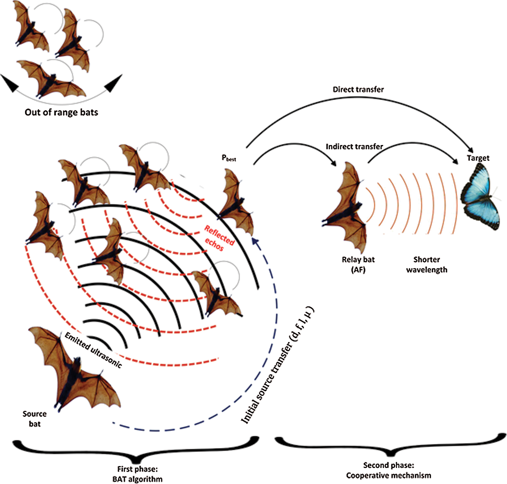
Figure 4: Schematic diagram of iBAT-COOP system model
The source node retrieves the required data within a swarm by knowing the status and position updates of other bats to perform the initial best transfer. For ease of use, position and velocity are relative to the distance so that we can consider only distance ‘d’ in place of these parameters. The optimal transfer of source bat to the best location is now subject to the distance, frequency, loudness, and SNR ( ). Source BAT is now ready to perform an initial migration to the best location to intelligently calculate all of these parameters and increase network authentication.
BAT algorithm phase simply follows the primitive principles of the bat during the flying mission. This biological behavior reduces the complexity of collision, distance, target, and unpredictable movements of flying bats and provides routing structure of relay positioning. To improve reliability, the second phase uses cooperative routing and follows the direct path transfer or relay path transfer. The destination receives multiple signals from a source, relay, and performs physical layer diversity-combining technique. Instead of SISO, cooperative routing can evaluate better SNR. This improvement can enhance the data rate, preserve the transmitting power, and prolong the communication range.
Multi-hop communication is preferred to meet the dynamic challenges of FANETs and cover a larger distance. For simplicity, bats are classified into two types: advance bats having better SNRs and less interference. The flowchart of iBAT-COOP system model (Fig. 5) where a group of few bats is listed out of range bats. These are not being participated in the network activities due to the limitations of transmission range and dimensions. Since the source bat emitted the ultrasonic waves and retrieves the reflected echo to perform the Pbest.
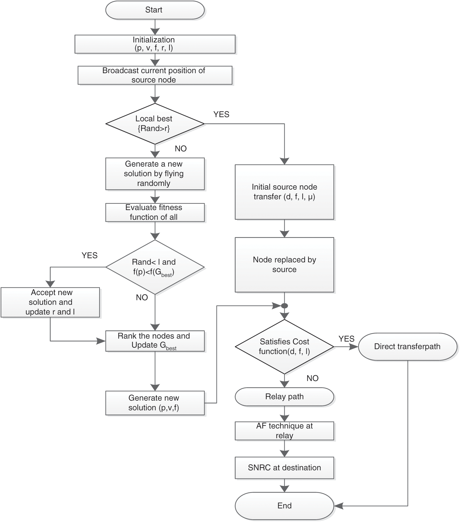
Figure 5: Flow chart of iBAT-COOP
This intelligent mutual replacement move of source bat not only considers the shortest distance to the best location but less interfered path to stay long. In this competition, the source bat is now apt to win the global best (Gbest) where the target or prey is one-step away. This optimal position helps the others to forward packets to the destination and that may call to use cooperation. Thus cooperative routing starts to transmit packets through this bat and the process staying continued till packets reached to the destination. Optimal placement of relay is also a challenge of FANETs, which is being overcome by opting for this natural act of bats. Now considering the Pbest and Gbest as relay bat of BAT algorithm and cooperative routing respectively and we can achieve iBAT-COOP routing protocol for FANETs. In normal communication, this routing continues cooperation till the relay path gives reliability but whenever the link of relay BATs is not reliable then the transfer of data should follow the available direct link path.
Different tasks of positioning, velocity, frequency, pulse rate, and loudness (p, v, f, r, l) are initialized. Bats update their positions and velocities by adjusting frequency according to neighbor location or solution using Eqs. (1)–(3). Emission of pulse rate increases in local search space when it finds a local solution and reduces the loudness accordingly. Hence, a new local solution is generated for each bat, which is obtained from the solutions of local search space. This local best solution enables the source bat to move intelligently for mutual replacement. The loudness and emission of the pulse rate of bats are updated iteratively and they can also accept new solutions when no local best solution is found. This new solution can be obtained from a random flight of bat with varying loudness and emission of pulse rate.
Source bat broadcast an information packet, which includes important indicators of distance, frequency, loudness, and SNR ( ). The echoes are reflected from prey/target which refers to the vital knowledge to those bats that have also transmitted the ultrasonic waves. In the transmission of packets, each bat can identify its neighbors within the transmission range. Further, under a certain threshold, it can also maintain a queue of neighbors separately and can easily identify the finest forwarder for transmission of the packet. Bats calculate the weights using Eq. (9).

where, Ci is the cost function of ith individual and  is constant of proportionality.
The process of cooperation of non-overlapping transmission of source and relay is completed in two stages. Source Si in a first stage, transmit information to relay R and destination D simultaneously. Similarly, R transmits the received information to D only in the second stage. Any information received in first stage at R and D expressed in Eq. (10):

where P1 is power transmitted by source, xsi is a symbol of information which is transmitted by ith source Si, the characteristics of wireless medium are HSiRi and HSiDi which are from source to relay (Si to Ri) and source to destination (Si to Di) respectively. These are the coefficients of complex Gaussian random variable with zero mean, variance  and expressed as C
  . The channel variance
  is modeled in Eq. (11).

where dij is the distance between the node i and j while the propagation loss factor is represented as  and
and  . These factors are constant values and depend on the propagation environment. Moreover, noise components are nSiRi and nSiDi which are incorporated in the links from Si to Ri and Si to Di respectively [31]. Next, the amplified symbol is forwarded from Ri to destination Di with power, P2. Now signal received at destination in the second stage is modeled in Eq. (12).

 When transmitted symbol is received by relay correctly and else
  . Signal
  is received at the destination after passing from the link S–R. This link may or may not be faded and the same as xsi. The noise terms are modeled as zero-mean complex Gaussian random variables. Destination Di uses the Fixed Ratio Combining (FRC) technique and combines the received signals of Si and Ri whereas P is the total transmitted power such that P = P1 +P2.
6.5 Relay Selection and Routing Phase
Assume the source bat has ‘n’ possible neighbors as in Fig. 6, within its vicinity and it should try to select a most appropriate neighbor as a relay using Eq. (9). Moreover, instantaneous channel condition, cost factor, distance, and SNR are also taken into consideration for this selection. Neighboring bats should be selected as relays if the cost function Ci is higher. Therefore, the source bat can get an excellent relay between the neighboring countries. After that, it starts receiving relay beat information packets and waits for the delivery of these packets. In addition, unnecessary packets are discarded at the destination, such as packets received from a neighboring bat or a packet received from a direct link that has already been sent by source bat during the hold time. Whenever a packet is received at the destination, this is now responsible to transmit an acknowledgment to the neighbors and unnecessary forwarding to other neighbors is discarded. In other words, the packet is being broadcasted by source bat while the relay bat is recognized with the help of cost function.
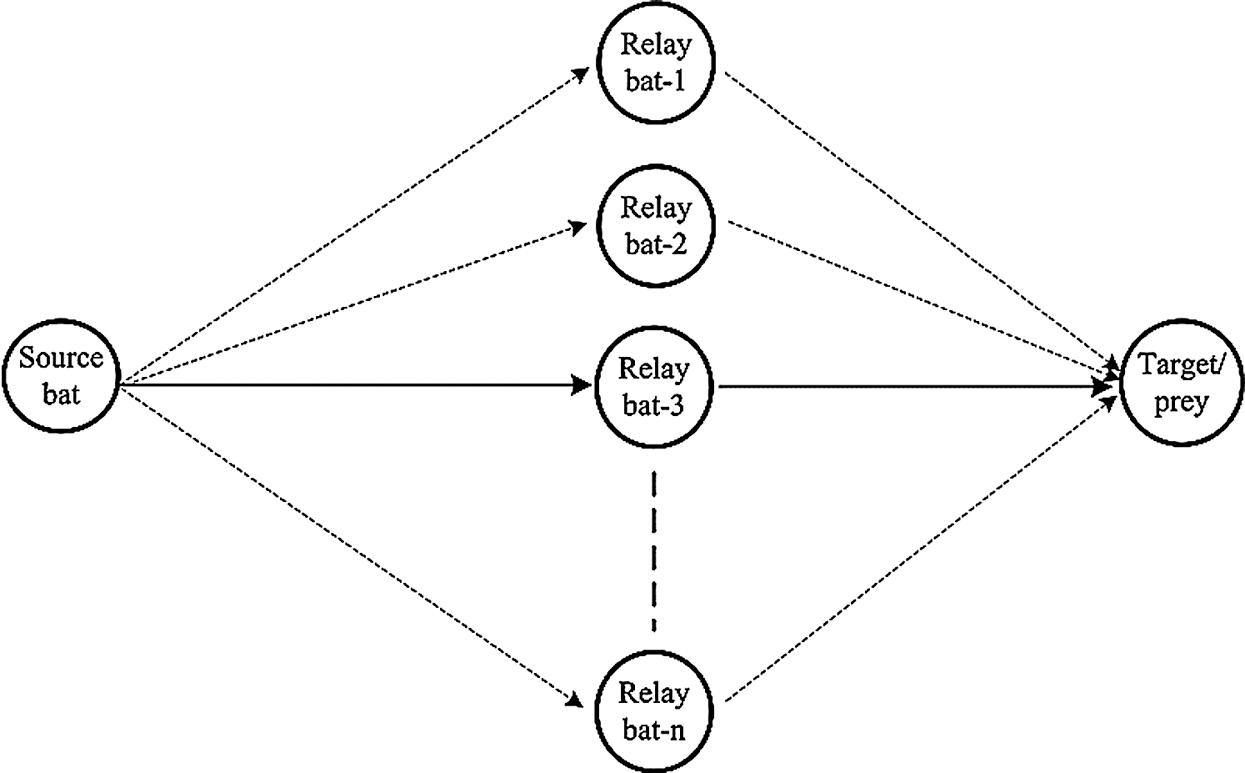
Figure 6: Relay selection phase
When the route of source bat has ‘n’ accessible relay bats and target/prey for this is on next hop, then the relay bat will not at all trigger cooperation. Consequently, it can facilitate the bats to achieve better SNR which has been reduced after packet transmission. This can be achieved by using Eq. (13).

Relay strategy phase details the feature of AF technique at the relay, Ri. In this way signal received from Si is multiplied by a factor of amplification  . This should be achieved before the forwarding of the packet to the target and can be expressed as
  . If Ps is the transmission power at source and Pr is the transmission power at the relay, then factor
  can be expressed as in Eq. (14) [30].

This relay gain is also known as Channel State Information (CSI) assisted AF relay gain. Since knowledge estimation of the instantaneous channel of S–R is required for a relay node to furnish the gain amplification at R. Now received signal of the second stage can be rewritten as in Eq. (15).

where  is a link power of R–D and different in wattage from Ps and Pr. Rayleigh distributed is modeled as the amplitude of the received signal (S to D, S to R, and R to D) and links are supposed to be independent and modeled as Rayleigh fading.
6.7 Selection Strategy at Destination
This is a final and decision making phase of the proposed protocol where the destination node receives two signals of  and
and  . These signals are combined by combining SNRC on the other hand is used as combining strategy. Instead of simply combining and adding received signals, SNRC is weighted with a constant ratio. The outcome of this ratio indicates the average channel quality concerning different influences and effects on the channel. Let us consider that if there is a single relay node then SNRC can be computed as in Eq. (16).

where yd indicates the output which combined the signals at the destination. Hence this equation can be extended and will get used to the relay nodes of any numbers. The coefficients c1 and c2 are the different weights of two links and channel coefficients respectively and these are also the function of power. The ratio between them can be expressed as in Eqs. (17) and (18) [32].

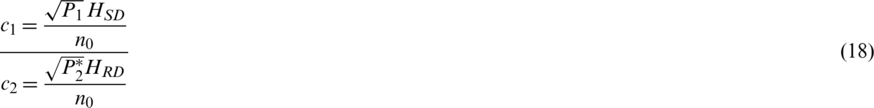
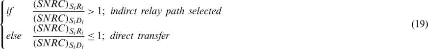
In the case of AF technique, 2:1 is an optimal value of the ratio of the weights [28]. Suppose there are many relay bats available in a route of source bat and choice of selection is either direct transfer or indirect relay path transfer depends on the following conditions. If the ratio of SNRC between source, relay, and source, the destination is greater than 1, then the source will go to the choice of indirect relay path transfer. Similarly, rest the bats which do not satisfy this condition will follow the direct transfer. These conditions can help the bats to minimize unnecessary load on relay for packet forwarding to destination. The mathematical model of these conditions is expressed in Eq. (19).
Consequently, the average energy of the unity for the transmitted symbol is xs, then we can compute the SNR of the FRC output using Eq. (20).

where  and
and  are the SNR representations of node links from Si to Ri and Si to Di respectively whereas dSiRi and dRiDi are distances of the source to relay and relay to destination respectively.
The idea of cooperative diversity allows the handling of dynamic variations in the flying threshold. Hence, iBAT-COOP protocol is a practical contender for data as well as time-parameter based decisive applications. Initially, nodes deployment is considered random. Simulation is run in rounds in which the corresponding values of respective protocols are updated accordingly. In every round, all the alive nodes should send the threshold information to the destination. These nodes are responsible to share the important physical metrics of ( ) and cost function value with their neighbors. It can help the nodes to keep updating the dynamic circumstances of the network.
Tab. 1 indicates the numerical differentiation of BAT and iBAT-COOP in terms of packet loss ratio with an equal increase in vehicle density. Improvement of 81% in terms of packet loss ratio is a significant outcome especially when dealing in with a dynamic network. Fig. 7 shows the self-explanatory comparison plots of iBAT-COOP and BAT protocols. A great reduction of packet loss can be seen due to the availability of a larger number of cooperative nodes. Performance comparison indicates that iBAT-COOP improves the success possibility of receiving packets.
Table 1: Packet loss ratio vs. No. of vehicles
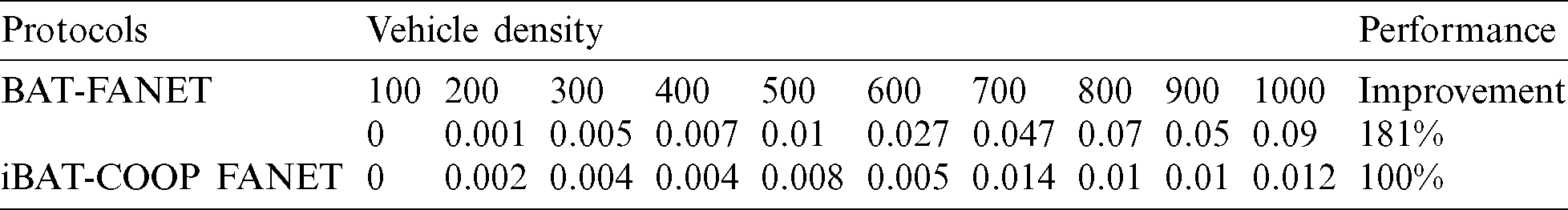
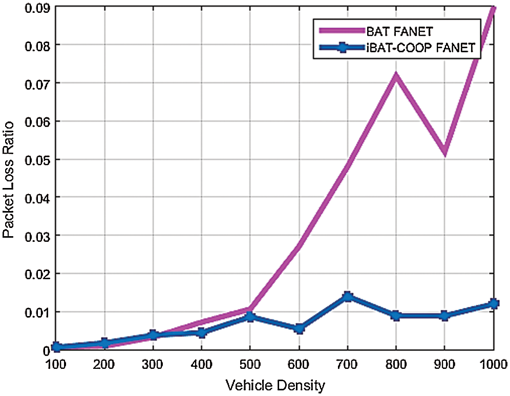
Figure 7: Packet loss ratio vs. vehicle density
Fig. 8 presents the comparison of end-to-end delay of BAT and iBAT-COOP protocols, where the proposed protocol shows less end-to-end delay than the BAT. On the other hand, the placement of forwarding nodes in BAT protocol is faraway which has caused a higher delay. Moreover, iBAT-COOP protocol can load balancing during the variations of threshold and cost function. BAT protocol only considers packet forwarding and uses minimum hop communication but high mobility of nodes may increase delay and loss of packets. Thus, packets are required to be retransmitted in BAT, which escalates the end-to-end delay.
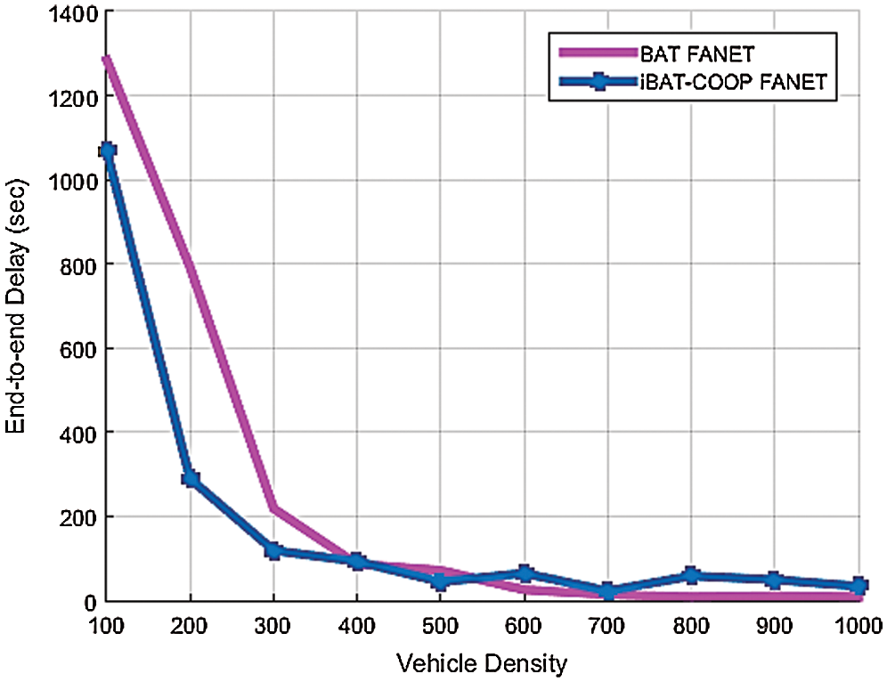
Figure 8: End to end delay vs. vehicle density
The iBAT-COOP protocol is simulated based on computation where only reliable packet forwarding is considered. To improve this, minimum retransmission of packets is taken into consideration particularly when cooperative routing is considered. In this case, packets of iBAT-COOP protocol reach the destination with lower delay. The numerical result of BAT and iBAT-COOP protocols in terms of end-to-end delay is given in Tab. 2. Improvement of 27% is achieved by iBAT-COOP protocol as compared to BAT protocol. Fig. 9 plots the comparison of BAT and iBAT-COOP average link duration.
Table 2: End-to-End delay vs. No. of vehicles
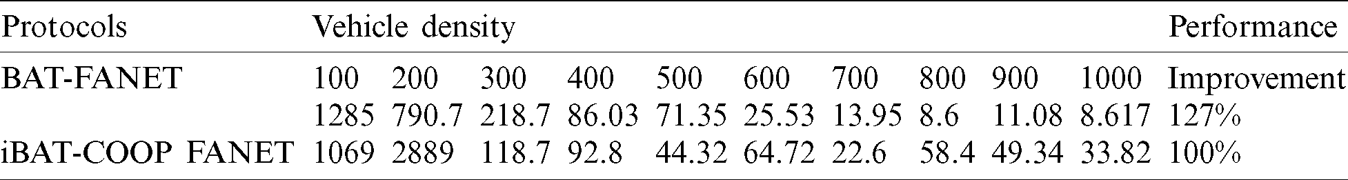
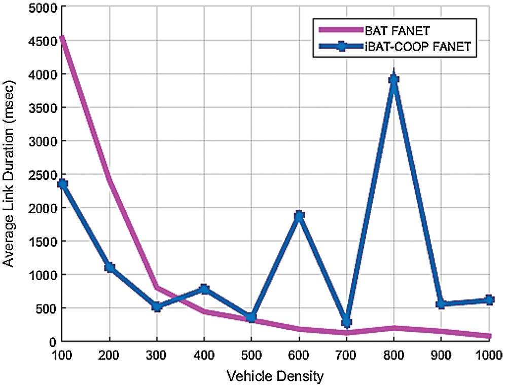
Figure 9: Average link duration vs. vehicle density
Thus instead of the mean, we have adopted the concept of average link duration for every forwarder node. The resultant plots have specified an impressive use of relays in iBAT-COOP which can contribute to providing better average link duration as compared to BAT protocol. Instead of a single path, iBAT-COOP uses multipath to forward the received packet which is further combined at the destination. Tab. 3 results show the numerical analysis of BAT and iBAT-COOP protocols, which has thus achieved an improvement of 25% in terms of average link duration. Since cooperative routing consider relays and manage the direct path transfer and indirect path transfer. As a result, there is a higher probability of an availability of link from one of them.
Table 3: Average link duration vs. No. of vehicles
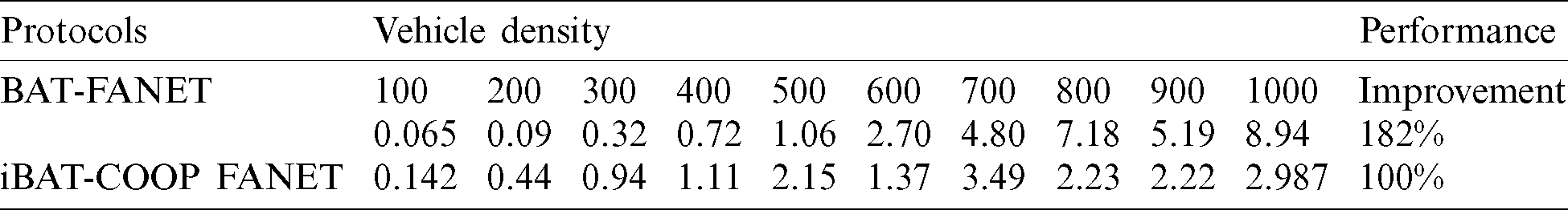
Fig. 10 shows tremendous reduction of transmission loss in iBAT-COOP than BAT protocol. This is due to the implementation of the prioritization of relay strategy, adopting the role of cooperation, and considering the SNRC in the design of iBAT-COOP protocol. It is always a vital challenge to minimize the losses of FANETs; iBAT-COOP protocol has achieved a massive reduction in transmission loss as compared to BAT protocol due to the adaptation of embedded cooperation features.
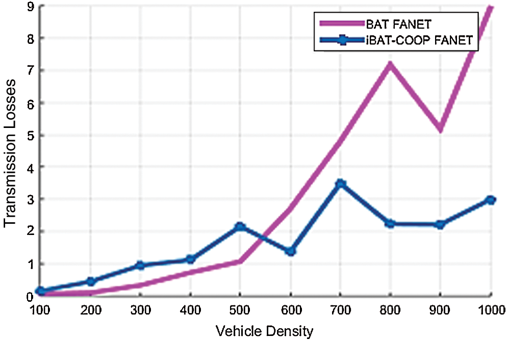
Figure 10: Transmission loss vs. vehicle density
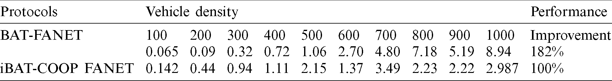
Further, BAT protocols do not study the noise factors and losses, so that their performance is much less as compared to iBAT-COOP protocol. Numerical characteristics of BAT and iBAT-COOP protocols in respect of transmission loss is presented in Tab. 4. Effective use of cooperative relay nodes has ensured to minimize the losses. This efficiency is not only reducing the computational issues of FANETs but also beneficial in real-time applications.
Table 4: Transmission loss vs. No. of vehicles
This paper has presented the iBAT-COOP routing protocol for FANETs which has demonstrated promising performance in reducing the network end-to-end delay, packet loss, and transmission loss as the link average duration is improved. Optimizing the average duration of engagement is being considered at the expense of the time delay because the appropriate selection of relay nodes is taken into account. The proposed protocol takes into account the cooperative routing along with SNRC computation. The cooperation technique not only reduces the dependency on channel estimation, but also improves the reliability of successful packet delivery at the destination. The use of the optimal cost computation formula has provided the concept of load balancing on the nodes. Calculating the error could be the future recommendation of this study.
Acknowledgement: Authors highly acknowledge the Quaid-i-Azam University, Iqra National University, Qasim University (Pakistan), Onizah College of Engineering and Information Technology (KSA), and the The National of Malaysia, (Malaysia) for collaborative support in this work.
Funding Statement: The authors funding support for this work by the Department of Information Technology, College of Computer, Qassim University, Buraydah, Saudi Arabia.
Conflicts of Interest: The authors declare that they have no conflicts of interest to report regarding the present study.
1. M. A. Khan, I. U. Khan, A. Safi and I. M. Quershi. (2018). “Dynamic routing in flying ad-hoc networks using topology-based routing protocols,” Drones, vol. 2, no. 3, pp. 27. [Google Scholar]
2. J. Souza, J. Jailton, T. Carvalho, J. Araújo and R. Francês. (2019). “A proposal for routing protocol for FANET: A fuzzy system approach with QoE/QoS guarantee,” Wireless Communications and Mobile Computing, vol. 2019, pp. 1–10. [Google Scholar]
3. M. Imtiaz and Y. Cho. (2019). “Adaptive hello interval in FANET routing protocols for green UAVs,” IEEE Access, vol. 7, no. 2019, pp. 63004–63015. [Google Scholar]
4. C. Sung-Chan, J. Park and J. Kim. (2019). “A networking framework for multiple-heterogeneous unmanned vehicles in FANETs,” in 2019 Eleventh Int. Conf. on Ubiquitous and Future Networks, Split, Croatia, July 2–5, IEEE, pp. 13–15. [Google Scholar]
5. G. Lav, R. Jain and G. Vaszkun. (2016). “Survey of important issues in UAV communication networks,” IEEE Communications Surveys & Tutorials, vol. 18, no. 2, pp. 1123–1152. [Google Scholar]
6. A. J. Aparna, Y. P. Singh and V. S. Deshpande. (2020). “QMAA: QoS and mobility aware ACO-based opportunistic routing protocol for MANET,” in Computational Intelligence in Data Mining, Springer, pp. 63–72, . https://ieeexplore.ieee.org/document/7317490. [Google Scholar]
7. R. R. Shringar, D. K. Lobiyal, S. Das and S. Kumar. (2015). “Analytical evaluation of directional-location aided routing protocol for VANETs,” Wireless Personal Communications, vol. 82, no. 3, pp. 1877–1891. [Google Scholar]
8. H. Shahab, G. Abbas, Z. H. Abbas and T. Baker. (2019). “DABFS: A obust routing protocol for warning messages dissemination in VANETs,” Computer Communications, vol. 147, pp. 21–34. [Google Scholar]
9. A. Ghulam, Z. H. Abbas, S. Haider, T. Baker, S. Boudjit et al. (2020). , “PDMAC: A priority-based enhanced tdma protocol for warning message dissemination in VANETs,” MDPI Sensors, vol. 20, no. 1, pp. 45. [Google Scholar]
10. D. B. Johnson, D. A. Maltz and J. Broch. (2001). “DSR: The dynamic source routing protocol for multi-hop wireless ad hoc networks,” Ad Hoc Networking, vol. 5, no. 1 pp. 139–172. [Google Scholar]
11. B. Thar, J. M. García-Campos, D. G. Reina, S. Toral, H. Tawfik, D. Al-Jumeily, and A. Hussain. (2018). “GreeAODV: An energy efficient routing protocol for vehicular Ad Hoc networks,” in Int. Conf. on Intelligent Computing, Springer, Cham, Bengaluru, India, pp. 670–681. [Google Scholar]
12. J. Rachna and I. Kashyap. (2019). “An QoS aware link defined OLSR (LD-OLSR) routing protocol for MANETS,” Wireless Personal Communications, vol. 108, no. 3, pp. 1745–1758. [Google Scholar]
13. C. Zheng, W. Zhou, S. Wu and L. Cheng. (2020). “An adaptive on-demand multipath routing protocol with qos support for high-speed MANET,” IEEE Access, vol. 8, pp. 44760–44773. [Google Scholar]
14. B. S. Kumar and P. M. Khilar. (2014). “SIR: A secure and intelligent routing protocol for vehicular Ad Hoc network,” IET Networks, vol. 4, no. 3, pp. 185–194. [Google Scholar]
15. L. Zhao, B. Yin, M. X. Gao and X. Zhao. (2020). “Improved GPSR routing protocol based on weight function in shipborne Ad Hoc networks,” Materials Science and Engineering, vol. 768, no. 5, pp. 52134. [Google Scholar]
16. B. Ilker, O. K. Sahingoz and Ş. Temel. (2013). “Flying Ad-hoc networks (FANETsA Survey,” Ad Hoc Networks, vol. 11, no. 3, pp. 1254–1270. [Google Scholar]
17. Z. Zhigao, A. K. Sangaiah and T. Wang. (2018). “Adaptive communication protocols in flying Ad Hoc network,” IEEE Communications Magazine, vol. 56, no. 1, pp. 136–142. [Google Scholar]
18. D. A. Korneev, A. V. Leonov and G. A. Litvinov. (2018). “Estimation of mini-UAVs network parameters for search and rescue operation scenario with Gauss–Markov mobility model,” 2018 Systems of Signal Synchronization, Generating and Processing in Telecommunications, Minsk, Belarus, pp. 1–7, . https://ieeexplore.ieee.org/abstract/document/8457047. [Google Scholar]
19. D. Kim and J. Lee. (2017). “Topology construction for flying Ad Hoc networks (FANETs),” 2017 Int. Conf. on Information and Communication Technology Convergence, Jeju, South Korea, pp. 153–157. [Google Scholar]
20. I. Bekmezci, I. Sen and E. Erkalkan. (2015). “Flying Ad Hoc networks (FANET) test bed implementation,” 2015 7th Int. Conf. on Recent Advances in Space Technologies, Istanbul, Turkey, pp. 665–668. [Google Scholar]
21. M. Mohammad, W. Saad, M. Bennis, Y. H. Nam and M. Debbah. (2019). “A tutorial on UAVs for wireless networks: Applications, challenges, and open problems,” IEEE Communications Surveys & Tutorials, vol. 21, no. 3, pp. 2334–2360. [Google Scholar]
22. L. Jiangbin, Y. Zeng, R. Zhang and T. J. Lim. (2016). “Placement optimization of UAV-mounted obile base stations,” IEEE Communications Letters, vol. 21, no. 3, pp. 604–607. [Google Scholar]
23. Z. Zhongliang and T. Braun. (2012). “Topology control and mobility strategy for UAV Ad-Hoc networks: A survey,” in Joint ERCIM eMobility and MobiSense Workshop, Santorini, Greece Citeseer, pp. 27–32. [Google Scholar]
24. K. Singh and A. K. Verma. (2014). “Applying OLSR routing in FANETs,” 2014 IEEE Int. Conf. on Advanced Communications, Control and Computing Technologies, Ramanathapuram, India, pp. 1212–1215, . https://ieeexplore.ieee.org/abstract/document/7019290. [Google Scholar]
25. R. Stefano, K. Krużelecki, G. Heitz, D. Floreano and B. Rimoldi. (2015). “Dynamic routing for flying Ad Hoc networks,” IEEE Transactions on Vehicular Technology, vol. 65, no. 3, pp. 1690–1700. [Google Scholar]
26. R. Sebastian, M. Putzke and C. Wietfeld. (2013). “Ad Hoc self-healing of OFDMA networks using UAV-based relays,” Ad Hoc Networks, vol. 11, no. 7, pp. 1893–1906. [Google Scholar]
27. A. Belbachir, J. Escareno, E. Rubio and H. Sossa. (2015). “Preliminary results on UAV-based forest fire localization based on decisional navigation,” 2015 Workshop on Research, Education and Development of Unmanned Aerial Systems, Cancun, Mexico, pp. 377–382, . https://ieeexplore.ieee.org/abstract/document/7441030. [Google Scholar]
28. G. Ganbayar, A. P. Shrestha and S. J. Yoo. (2017). “Robust and reliable predictive routing strategy for flying Ad-Hoc networks,” IEEE Access, vol. 5, pp. 643–654. [Google Scholar]
29. S. A. Hadiwardoyo, C. T. Calafate, J. C. Cano, Y. Ji, E. H. Orallo et al. (2019). , “3D simulation modeling of UAV-to-car communications,” IEEE Access, vol. 7, pp. 8808–8823. [Google Scholar]
30. W. Zhiqing, H. Wu, Z. Feng and S. Chang. (2019). “Capacity of UAV relaying networks,” IEEE Access, vol. 7, pp. 27207–27216. [Google Scholar]
31. M. A. Khan, I. M. Qureshi and F. Khanzada. (2019). “A hybrid communication scheme for efficient and low-cost deployment of future flying Ad-Hoc network (FANET),” Drones, vol. 3, no. 1, pp. 1–16. [Google Scholar]
32. O. O. Sami, M. Atiquzzaman, P. Lorenz, M. H. Tareque and M. S. Hossain. (2019). “Routing in flying Ad Hoc networks: Survey, constraints, and future challenge perspectives,” IEEE Access, vol. 7, pp. 81057–81105. [Google Scholar]
33. K. Pardeep and S. Verma. (2019). “Research challenges in airborne Ad-hoc networks (AANETs),” in Proc. of 2nd Int. Conf. on Communication, Computing and Networking, Singapore: Springer, pp. 261–270. [Google Scholar]
34. K. Ali, F. Aftab and Z. Zhang. (2019). “Bio-Inspired clustering scheme for FANETs,” IEE Access, vol. 7, pp. 31446–31456. [Google Scholar]
35. Q. Yaohong, F. Zhang, X. Wu and B. Xiao. (2019). “Cooperative geometric localization for a ground target based on the relative distances by multiple UAVs,” Science China Information Sciences, vol. 62, no. 1, pp. 10204. [Google Scholar]
36. I. Shayla, O. O. Khalifa, A. H. A. Hashim, M. K. Hasan, M. A. Razzaque et al. (2020). , “Design and evaluation of a multihomingbased mobility management scheme to support inter-technology handoff in PNEMO,” Wireless Personal Communications, vol. 114, pp. 1133–1153. [Google Scholar]
37. I. Shayla, M. K. Hasan and A. H. A. Hashim. (2020). “A packet delivery cost analysis of a flow-enabled proxy NEMO scheme in a distributed mobility anchoring environment,” Elektronika ir Elektrotechnika, vol. 26, no. 4, pp. 65–71. [Google Scholar]
 | This work is licensed under a Creative Commons Attribution 4.0 International License, which permits unrestricted use, distribution, and reproduction in any medium, provided the original work is properly cited. |