DOI:10.32604/cmc.2021.013151
| Computers, Materials & Continua DOI:10.32604/cmc.2021.013151 | |
| Article |
Automotive Lighting Systems Based on Luminance/Intensity Grids: A Proposal Based on Real-Time Monitoring and Control for Safer Driving
1Department of Civil Engineering & Research Group “Lighting Technology for Safety and Sustainability”, University of Granada, Granada, 18071, Spain
2Business School, Sichuan University, Chengdu, 610064, China
*Corresponding Author: Antonio Peña-García. Email: pgarcia@ugr.es
Received: 28 July 2020; Accepted: 11 September 2020
Abstract: The requirements for automotive lighting systems, especially the light patterns ensuring driver perception, are based on criteria related to the headlamps, rather than the light perceived by drivers and road users. Consequently, important factors such as pavement reflectance, driver age, or time of night, are largely ignored. Other factors such as presence of other vehicles, vehicle speed and weather conditions are considered by the Adaptive Driving Beam (ADB) and Adaptive Front-lighting System (AFS) respectively, though with no information regarding the visual perception of drivers and other road users. Evidently, it is simpler to simulate and measure the light emitted by the lamps than the light reflected by the pavement or emitted by other vehicles. However the current technology in cameras and light sensors, communication protocols, and control of Light Emitting Diodes (LED), combined with decision-making techniques applied to large amounts of data, can open a new era in the operation of headlamps and thus ensure the visual needs of drivers in real time and under actual road conditions. The solution lies in an interaction road-sensor-headlamp, which is not based on the light emitted by headlamps, but rather on the light perceived by the drivers. This study thus proposes a dual grid based on luminance and luminous intensity, which would manage the headlamps by optimizing driver perception and the safety of all road users.
Keywords: Vehicle systems; optical sensing; LED control; automotive lighting
Lighting and signaling systems in motor vehicles have progressed just as quickly as the most cutting-edge systems in modern cars. This constant innovation has frequently permitted the implementation of new technologies even before regulations actually included them. One of the most striking cases is that of Adaptive Front-lighting Systems (AFS) and Adaptive Driving Beams (ADB), the first systems to adapt their light patterns to characteristics, such as road type (urban or interurban, based on speed or public lighting), weather conditions and presence of other vehicles. Because of the complexity of vehicle-headlamp communication and its technical feasibility, the automotive industry fast-tracked their design and testing within the framework of existing regulations until an ad hoc regulatory framework was finally put in place.
This apparent shift between technology and regulation was far from negative. The main regulatory frameworks, namely, the United Nations European Commission for Europe (UNECE) as reflected in the ECE Regulations, and the National Highway Traffic Safety Administration in the USA, with the Federal Motor Vehicles Safety Standard 108 (FMVSS 108), did their best to include the new advances during the 1990s and 2000s to avoid any regulatory gap. Thus, thanks to amendments to existing regulations, AFS were gradually installed in vehicles. During this period, observations, field research, and experience [1–3] led to the approval of more exhaustive regulations such as the ECE 123 [4].
In spite of their relative complexity, AFS and ADB are not expert systems since there is no learning from the inputs, and the fixed outputs only depend on a few binary parameters (e.g., highway or conventional road, adverse or favorable weather, etc.).
Apart from the overall impact of these new technologies, their way of lighting roads and users, the basic visual tasks of drivers remained the same. Furthermore, the appearance of more intuitive software for optical design, not to mention certain regulatory changes such as the shift from illuminance to luminous intensity criteria for lighting functions, could have been an obstacle to understanding the psychophysics underlying the visual tasks of drivers, and also hindered any possibility of new perspectives and improvement.
This paper examines vehicle lighting systems from the visual perspective of drivers. This analysis highlights the need for other parameters such as road luminance for certain visual tasks, as well as the need for a new philosophy to manage the relationship between road, sensors, and headlamps. The result is a real-time adaptation of headlamp output to the needs of drivers in each moment and circumstance.
1.1 Automotive Lighting and Signaling
Automotive lighting or vehicle lighting in non-specialized contexts generally refers to all the light-emitting devices mounted in vehicles, regardless of their function. However, there is a distinction between “lighting” and “signaling”. Since the context is clear, the adjectives “automotive” and “vehicle” will be omitted from this point forward.
“Lighting systems” or “lighting functions” refer to the devices installed in motor vehicles that allow drivers to see the road surface and its borders, and to detect obstacles as well as road users such as pedestrians, cyclists, and other drivers. This is accomplished by means of reflection and/or retroreflection. The main lighting functions are the low beam, high beam, and front fog lamps. Lighting functions also permit other drivers and pedestrians to detect the vehicle by direct vision (Fig. 1).
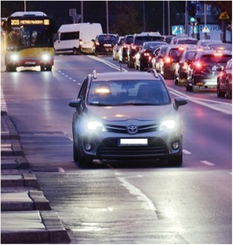
Figure 1: Direct vision of the low beam or an approaching car. (Free image from https://pixabay.com/)
• “Signaling systems” or “signaling functions” are those devices installed in motor vehicles that allow other road users (pedestrians, cyclists, and other drivers) to detect the vehicle. They include turn indicators, rear position lamps, daytime running lamps, stop lamps, back up lamps, etc.
• Although these systems include elements that permit communication between different vehicle devices, and even other functions not strictly related to lighting and signaling, this study focuses on light emission and perception. Engines, wiring, ballasts, microprocessors, communication protocols etc. incorporated into the light-emitting devices are thus outside the scope of this research.
• Lighting and signaling functions are hardly isolated from each other. Rather, they have frequent visual interactions that have an impact on other road users when they detect vehicles and vehicle movement. For example visual interactions between daytime running lamps and turn indicators [5,6], other lighting functions [7] and even the perception of vehicle speed [8], have been reported in the literature. In addition, even though the interaction of vehicle lighting and signaling with public lighting in streets and roads has still not been studied in any depth, research has shown its impact on the visual tasks of drivers [9].
1.2 Principles of Automotive Lighting and Signaling
This section describes how lighting and signaling functions work. The principles of these functions during night driving are shown in Fig. 2:
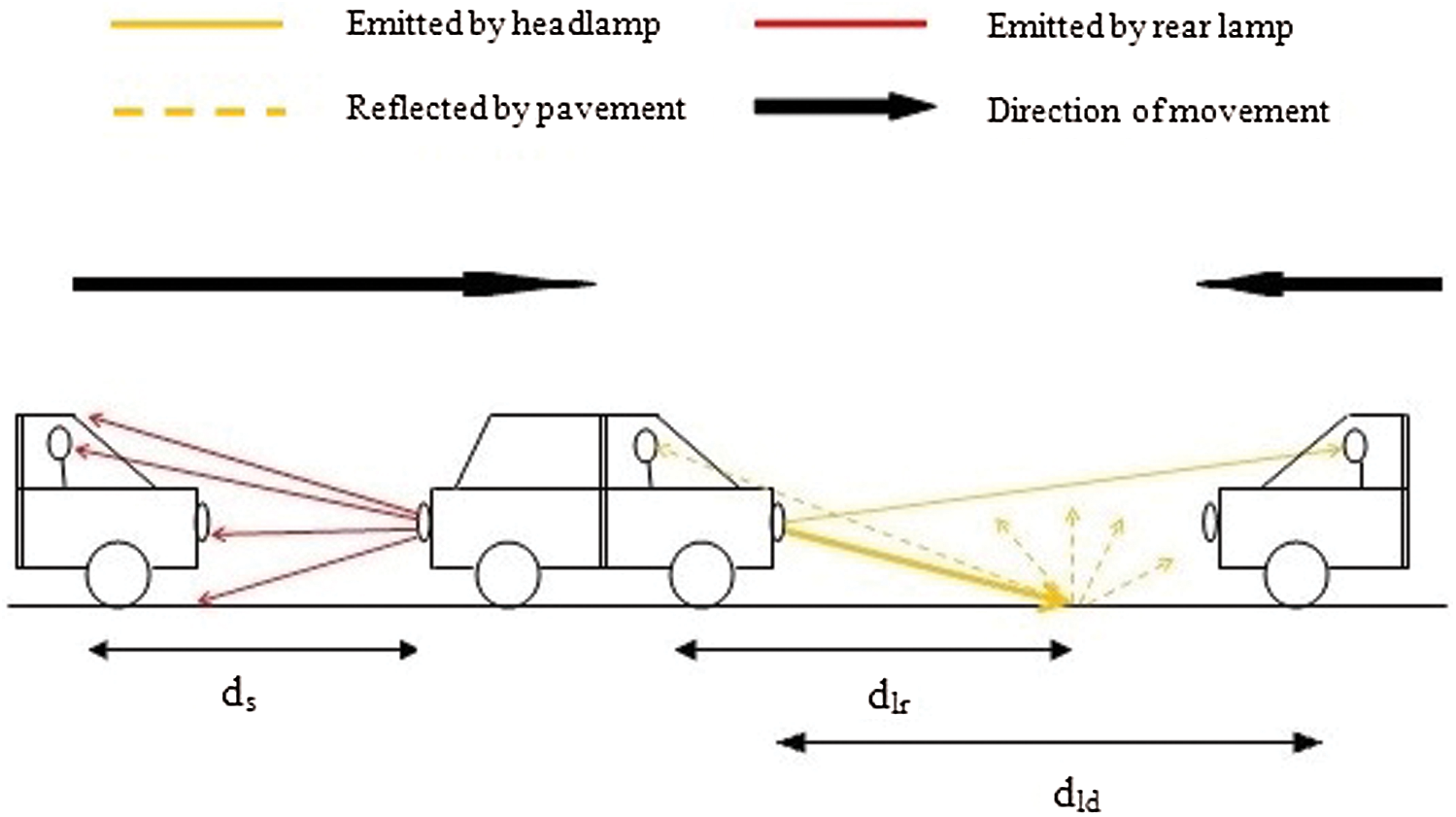
Figure 2: Basic scheme of the main visual tasks in driving. Dotted lines correspond to reflected light, whereas continuous lines represent light directly emitted by lighting (yellow) and signaling (red) functions. The distances ds, dlr and dld refer to signaling function-rear driver eye, point of retroreflection-own driver eye and lighting function-incoming driver eye, respectively
As portrayed in Fig. 2, the signaling device emits a luminous flux per unit of solid angle within one spatial distribution described by its luminous intensity matrix  , where
  and
and  are the angles between the horizontal optical axis of the lamp and the observer’s eye. After passing through the ocular media, the luminous flux reaches the retina and is processed by the photoreceptors (cones, rods, and intrinsically photosensitive retinal ganglion cells [ipRGC]). This results in visual and non-visual effects.
However, the lighting functions in vehicles work in different ways. First, the low and high beams, and the front fog lamps emit a luminous flux distribution towards the road ahead, illuminating the pavement and other elements such as the trees bordering the road, other vehicles, pedestrians, obstacles, information panels etc. Since the intensity distribution of the low beam is especially complex, with strong cut-off constraints to avoid glare, this study refers to this function without loss of generality.
Consequently, the road pavement reflects the received flux per unit of surface (illuminance) in all the directions. On most of the pavements used in roads and streets, this reflection is diffuse, with a strong backward component (retroreflection). The reflected flux per unit of surface and solid angle in the direction of the driver’s eye, namely, the luminance of the road and its obstacles, is directly related to the perceived brightness and determines the performance during the visual task, including the visual reaction time as established by Pieron’s Law [10–13].
In addition to reflection and retroreflection, the spatial distribution of the lighting functions also has components above the road, which are directly emitted in the direction of incoming drivers and other users as shown in Fig. 2. These rays allow users to detect vehicles without intermediate reflections, but they can also produce glare. In summary, the purposes of lighting functions are for drivers to see and for people and objects to be seen, whereas signaling functions are only designed to be seen.
Therefore, characterizing the dual working of lighting functions from a visual perspective is a technological challenge that involves more complex sensors and measurements. However, the need for good perception in real time clearly demands a new philosophy based on a complex feedback system. This means adapting headlamp output to their retroreflected light on the road. The first step is thus to propose a dual photometric grid that has not as yet been contemplated.
1.3 Photometric Requirements for Lighting Functions
Since the enactment of the first regulations almost one century ago, photometric requirements for lighting functions have never been homogeneous. Depending on the regulatory framework, they have been expressed in terms of illuminance or luminous intensity, and even changed from one to the other. Thus, the photometric requirements in the USA [14], and Canada [15] have always been expressed in terms of photometric intensity, whereas lighting functions in the UNECE framework (mainly European countries), China, and Japan, were first expressed in terms of illuminance on a vertical screen.
In the case of the UNECE, the regulations dealing with lighting functions were finally amended, and photometric requirements are now expressed in terms of luminous intensity [16]. Both criteria can be equivalent under certain conditions and present serious limitations. However, these limitations can now be overcome, thanks to expert systems that combine real-time inputs from luminance sensors, management of large amounts of data, and feedback communication with LED headlamps.
The proposal presented in this paper departs from the ECE regulations on lighting functions (low and high beams, and front fog lamps), whose photometric standards changed from illuminance to luminous intensity. Although the framework in USA and Canada did not change, the conclusions that question the accuracy of expressing lighting requirements in terms of luminous intensity are fully applicable to these countries.
Given the remarkably higher complexity of low beams in terms of light pattern, glare control, etc., they were used as the model in this study. In particular, the ECE regulations regarding this function have been analyzed before and after the change of photometric criteria from illuminance to intensity. They are the following:
– Regulation ECE 98: Versions from 23 February 2012 [17] including intensity requirements, and 16 October 2009 [18], still expressing photometric requirements in terms of illuminance for discharge lamps.
– Regulation ECE 112: Versions from 9 January 2013 [19] including intensity requirements, and 5 October 2006 [20], still expressing photometric requirements in terms of illuminance for filament lamps.
Figs. 3a and 3b show the respective grids presented in Annex 3 to these Regulations at that time.
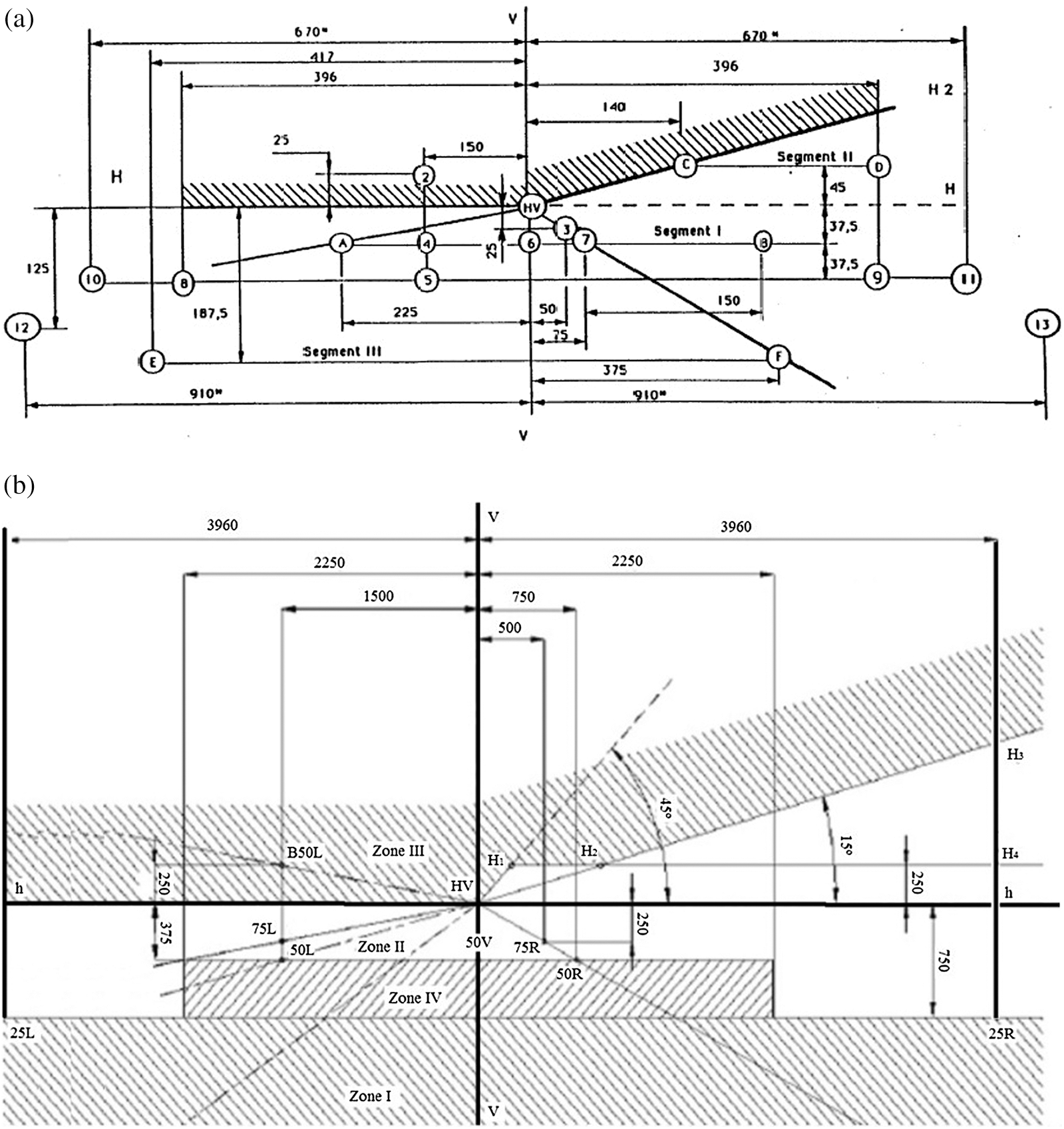
Figure 3: Photometric grids for discharge (a) and filament (b) right-handed low beams in the ECE regulatory framework. Dimensions in mm on one vertical screen at 25 m. Adapted from regulations ECE 98 (version from 2009, [18]) and ECE 112 (version from 2006, [20])
After the analysis of these requirements in Section 3, Section 4 presents a new proposal based on an expert system that permits real-time communication with luminance sensors and headlamps.
3 Limitations of the Current Regulatory Requirements for Automotive Lighting
Before the previously mentioned regulatory change in the ECE framework, mapping the illuminance at various points and in different zones with specific angular positions spread on vertical screens, was assumed to be an effective approach to establishing equivalences with the illuminance needed on the road surface, information panels, and the eyes of other drivers. Those values were thought to ensure safe and comfortable driving. After the switch to luminous intensity requirements, the photometric grids of Regulations ECE 98 and 112 did not change remarkably in terms of measurement points, but they did change in the quantity to be measured at these points.
An analysis of this regulatory evolution based on Lighting principles shows that there is still uncertainty in the prediction of luminance from the road and, thus of the visual and non-visual performance of drivers. More specifically, it is necessary to highlight the following:
1. The illuminance on one point of the road, its borders, and pedestrian faces, does not guarantee the necessary reflected luminance (emitted luminous flux per unit of surface and solid angle in the direction of the driver’s eye) to ensure accurate visual perception and the speedy reaction of drivers, when needed. The reflected luminance depends on surface properties such as reflectance [21]. This is a key point since it can vary dramatically with weather conditions (drought, rain, fog, etc.), presence of dirt or car oil, as well as many other factors.
2. Knowing the luminous intensity distribution emitted by a headlamp is useful to predict the glare perceived by other road users [22], but it is also insufficient to predict retroreflected luminance, and consequently, the retinal input that initiates both visual and non-visual paths.
3. A philosophy based on external measurements of lighting quantities from the headlamp (illuminance on road or screens, intensity somewhere in the space, etc.) does not allow vehicle systems to control their performance in real driving unless the road surfaces have an extensive array of sensors and communicate with all the vehicles, a scenario that is not as yet feasible. The use of illuminance or luminous intensity makes it impossible to know whether the changing reflectance of the pavement or current atmospheric conditions ensure correct visibility, even if the luminous intensity emitted is right for standard conditions.
All these arguments could lead someone unfamiliar with automotive lighting to think that conventional photometric grids ignored basic principles of Lighting. However, this conclusion would be erroneous.
Until recently, illuminance or intensity-based photometric grids were logical because it was feasible and inexpensive to install several cells on one screen or install only one cell and move the headlamp by means of a goniometer. Furthermore, the desirable direct measurement of luminance from the driver’s position (the amount of light that the driver actually perceives from one given direction) with a classical luminance-meter, does not separate the contribution of each point of the road and the information panels. In other words, the average luminance in the visual field of the driver does not reveal whether there are road areas or borders that are either excessively or insufficiently illuminated. Even if this were viable, the effort would have been useless because the luminous intensity emitted by traditional headlamps (halogen or xenon) in each direction could not be easily increased or decreased to adapt to the changing conditions of the pavement and surroundings.
However, recent technological advances in optical sensing and LED headlamps have made it possible to overcome these problems and work with photometric grids that ensure the perception of the necessary luminance from the road and obstacles while maintaining the constraints of corneal illuminance in the eyes of the incoming drivers.
In summary, the photometric requirements for automotive lighting are not based on accurate parameters that ensure the correct performance of the visual tasks of drivers and, hence, the safety of all the road users. This paper presents a proposal that consists of a mixed luminance/intensity criterion. In spite of its apparent complexity, it is more logical from the perspective of visual performance and is fully compatible with the current technology to manage feedback systems.
4 Proposal of Dual Luminance-Intensity Grids Based on Sensor-Headlamp Feedback
As discussed in Section 3, the parameters ensuring driver perception of the road are luminance from the pavement and the luminous intensity from other vehicles. Although the objective of this study is not to propose specific vehicle configurations or measurement techniques, it is possible to establish the masterlines that define the functioning of expert systems that allow a more realistic perception of road.
The main advances that have opened the door to such systems include the following: (i) The introduction of LED in lighting functions; (ii) The rapid evolution of the devices capable of measuring luminance with good spatial resolution; and (iii) The possibility of managing large amounts of data in real time.
The advantage of LED in comparison to halogen or xenon light sources is that they make it possible to dim or augment their flux without damaging or shortening their lifetime. Some of them can also be switched off when required. In regard to luminance measurements, even calibrated digital cameras can now be used to obtain accurate ones [23–25]. These cameras can measure the luminance on each pixel, which affords the possibility of determining the average luminance in a wide field as well as individual luminance from different points of the road. Finally, advances in the management of large amounts of data and decision-making [26–29] make it possible to decide how much luminous flux should be emitted by each LED to ensure the required amount of retroreflected luminance towards the eyes of the driver at each moment and point of the road surface.
For the first time, the synergy between these three factors permits lighting systems to adapt to the real perceptual needs of drivers, whose visual tasks are continuously undergoing changes and require an immediate response. The masterlines of measurements for design, in-house testing, and work during real driving can be given now that photometric grids based on luminance and intensity requirements are feasible. They are the following:
1. Calibration of the control system during the development phase to determine which input must be given to each array of LED based on the input received from the optical sensors.
2. Calibration of LED headlamps during the development phase to determine the relationship between the inputs received from the control system and their outputs in luminous flux.
3. Testing for official homologation or control of production in photometric tunnels.
4. Set of flux per LED array during real driving so that the road reflects the necessary luminance in spite of the meteorological conditions, pavement reflectance, driver age, etc.
In this new scenario, if minimum and maximum luminance values are assigned to points on the road such as those conventionally used in the regulations (75 R, 50 R, 50 V, 25 L, 25 R and other displayed in Fig. 3), they can be controlled with different pixels of luminance cameras. Moreover, the testing points for controlling glare for other drivers (HV, B50 L, 75 L, 50 L and others) must still be expressed in terms of luminous intensity because they are used to calculate the corneal illuminance on the eyes of incoming drivers.
The greater complexity of a dual testing method is clearly compensated by the certainty regarding the retinal flux received by drivers and the added safety value. The schematic configuration of the testing facilities is shown in Fig. 4.

Figure 4: Retroreflected light is measured by a device (digital camera or other) on a luminance-based grid for visual task points on the road. Glare points (above the road) are measured on a vertical screen according to current luminous intensity criteria. The LED of the lighting function are regulated based on the output of the control system to ensure the necessary luminance on the driver’s eye
This is especially important in urban environments and road tunnels, where the joint action of public and vehicle lighting is an issue of the highest priority for visual performance and safety. One characteristic of public and especially of tunnel lighting is its relatively low uniformity on the road (around 0.4), which sometimes even causes a flicker effect [30]. This means that the luminance perceived by drivers can continuously change despite the fact that the low beam provides stable flux. A real-time control on the low beam could compensate the road luminance fluctuations generated by infrastructure lighting. If there is no vehicle-mounted device to measure luminance, this control is not possible.
In summary, technological advances now make it possible to adapt the beams emitted by headlamps to the real needs of drivers at each moment and point of the road. This is feasible as long as the regulatory requirements for headlamps change to a dual photometric grid for lighting functions. There would be luminance requirements on the road and at surrounding points where the visual task is carried out by retroreflection, and there would also be intensity requirements for glare points. The goal is to control the headlamp outputs to ensure good visual performance.
One important aspect of automotive lighting is the way the beam patterns emitted by different lighting functions are measured. Another crucial issue is the difference between design or in-house testing and the real working conditions of this lighting during its lifetime mounted on vehicles. Over the years, there has been a duality between regulatory bodies in different countries. Some use luminous intensity emitted in some directions, whereas others work with illuminance on a vertical screen. Although both criteria can sometimes be equivalent in certain context, these differences have always been an obstacle to the real-time control of the visual needs of drivers.
The problem is that the main parameter determining the visual and non-visual performance of the drivers (luminance retroreflected on pavement and obstacles) continuously changes despite the fact that the low beam provides a stable flux. The reasons lie in the changing reflectance of pavements, shadows, presence of other vehicles, trees and urban lighting, weather conditions, and even personal circumstances such as driver age, visual health, etc. A real-time control on the low beam could compensate the fluctuations of road luminance. However, without a vehicle-mounted device to measure luminance and provide feedback from the headlamps, this control is not possible.
Major advances in optical sensors and big data management, together with the introduction of LED in lighting functions, has completely changed the panorama, especially for low beams, which are the most critical visual task for drivers.
This paper has proposed an architecture based on systems capable of dimming and increasing the voltage of LED, based on the visual needs of drivers at each moment and point of the road. The output of this system is determined by the continuous scanning of road and environmental luminance by an onboard sensor. The first step toward making this feasible was the regulatory change from illuminance or intensity requirements, to a dual grid based on luminance and luminous intensity for retroreflecting and direct vision points, respectively.
Beyond implementing this dual grid in the laboratories for testing, it is also possible to implement luminance sensors (electronic cameras or other devices) and communication protocols in real vehicles with a view to adapting LED headlamp output to the conditions of the road in real time. As result, the necessary luminance from the pavement can be ensured.
The potential adoption of these proposals would doubtlessly lead to more reliable testing and adaptive lighting to the changing conditions of the roads, which would enable safer driving.
Funding Statement: The author(s) received no specific funding for this study.
Conflicts of Interest: The authors declare that they have no conflicts of interest to report regarding the present study.
1. M. Sivak, B. Schoettle, M. J. Flannagan and T. Minoda. (2005). “Optimal strategies for adaptive curve lighting,” Journal of Safety Research, vol. 36, no. 3, pp. 281–288. [Google Scholar]
2. J. M. Sullivan and M. J. Flannagan. (2006). “Implications of fatal and nonfatal crashes for Adaptive Headlighting (Technical Report UMTRI-2006-1),” University of Michigan Transportation Research Institute. Ann Arbor, MI, USA. [Google Scholar]
3. A. Peña-García, P. Peña, A. Espín and F. Aznar. (2012). “Impact of adaptive front-lighting systems (AFS) on road safety: Evidences and open points,” Safety Science, vol. 50, no. 4, pp. 945–949. [Google Scholar]
4. United Nations Economic Commission for Europe (UNECE). (2008). “Regulation ECE No. 123—Uniform provisions concerning the approval of Adaptive Front-lighting Systems (AFS) for motor vehicles,” Geneva, Switzerland. [Google Scholar]
5. A. Peña-García, R. de Oña, A. Espín, F. Aznar, F. J. Calvo et al. (2010). , “Influence of daytime running lamps on visual reaction time of pedestrians when detecting turn indicators,” Journal of Safety Research, vol. 41, no. 5, pp. 385–389. [Google Scholar]
6. A. Peña-García, R. de Oña, P. A. García and J. de Oña. (2016). “Personal factors influencing the visual reaction time of pedestrians to detect turn indicators in the presence of daytime running lamps,” Ergonomics, vol. 59, no. 12, pp. 1596–1160. [Google Scholar]
7. M. Sivak, M. J. Flannagan, B. Schoettle and Y. Nakata. (2001). “Masking of front turn signals by headlamps in combination with other front lamps,” Lighting Research & Technology, vol. 33, no. 4, pp. 233–241. [Google Scholar]
8. D. Pešić, A. Trifunović, I. Ivković, S. Čičević and A. Žunjić. (2019). “Evaluation of the effects of daytime running lights for passenger cars,” Transportation Research Part F: Traffic Psychology and Behaviour, vol. 66, pp. 252–261. [Google Scholar]
9. A. Bacelar. (2004). “The contribution of vehicle lights in urban and peripheral urban environments,” Lighting Research & Technology, vol. 36, no. 1, pp. 69–78. [Google Scholar]
10. R. D. Luce. (1986). Response Times. New York: Oxford University Press. [Google Scholar]
11. D. Pins and C. Bonnet. (1996). “On the relation between stimulus intensity and processing time: Pieron’s law and choice reaction time,” Perception & Psychophysics, vol. 58, no. 3, pp. 390–400. [Google Scholar]
12. D. Pins and C. Bonnet. (1997). “Reaction times reveal the contribution of the different receptor components in luminance perception,” Psychonomic Bulletin & Review, vol. 4, no. 3, pp. 359–366. [Google Scholar]
13. D. C. Burr and B. Corsale. (2001). “Dependence of reaction times to motion onset on luminance and chromatic contrast,” Vision Research, vol. 41, no. 8, pp. 1039–1048. [Google Scholar]
14. National Highway Traffic Safety Administration (NHTSA). (2007). “Federal Vehicle Motor Safety Standard 108,” Washington D.C., USA. [Google Scholar]
15. Transport Canada-Road Safety and Motor Vehicle Regulation Directorate. (2005). “Canadian Vehicle Motor Safety Standard 108,” Ottawa, Canada. [Google Scholar]
16. United Nations Economic Commission for Europe. 2009(a). “Collective amendments to Regulations Nos. 19, 48, 98, 112 and 123; Proposal for draft 01 series of amendments to Regulation No. 98 (Headlamps with gas-discharge light sources). ECE/TRANS/WP.29/GRE/2009/21,” Geneva, Switzerland. [Google Scholar]
17. United Nations Economic Commission for Europe (UNECE). (2012). “Regulation ECE No. 98—Uniform provisions concerning the approval of motor vehicle headlamps equipped with gas-discharge light sources,” Geneva, Switzerland. [Google Scholar]
18. United Nations Economic Commission for Europe (UNECE). 2009(b). “Regulation ECE No. 98—Uniform provisions concerning the approval of motor vehicle headlamps equipped with gas-discharge light sources,” Geneva, Switzerland. [Google Scholar]
19. United Nations Economic Commission for Europe (UNECE). (2013). “Regulation ECE No. 112—Uniform provisions concerning the approval of motor vehicle headlamps emitting an asymmetrical passing-beam or a driving-beam or both and equipped with filament lamps and/or light-emitting diode (LED) modules,” Geneva, Switzerland. [Google Scholar]
20. United Nations Economic Commission for Europe (UNECE). (2006). “112—Uniform provisions concerning the approval of Regulation ECE No. 112—Uniform provisions concerning the approval of motor vehicle headlamps emitting an asymmetrical passing-beam or a driving-beam or both and equipped with filament lamps,” Geneva, Switzerland. [Google Scholar]
21. W. van Bommel. (2015). Road Lighting. Fundamentals, Technology and Application. Springer, Switzerland. [Google Scholar]
22. J. J. Vos. (2003). “Reflections on glare,” Lighting Research & Technology, vol. 35, no. 2, pp. 163–176. [Google Scholar]
23. D. Wüller and H. Gabele. (2007). “The usage of digital cameras as luminance meters,” in Proc. SPIE, vol. 6502, 65020U. [Google Scholar]
24. M. T. Vaaja, M. Kurkela, J. P. Virtanen, M. Maksimainen, H. Hyyppä et al. (2015). , “Luminance-corrected 3D point clouds for road and street environments,” Remote Sensing, vol. 7, no. 9, pp. 11389–11402. [Google Scholar]
25. O. Rabaza, E. Molero-Mesa, F. Aznar-Dols and D. Gómez-Lorente. (2018). “Experimental study of the levels of street lighting using aerial imagery and energy efficiency calculation,” Sustainability, vol. 10, no. 12, pp. 4365. [Google Scholar]
26. J. Wątróbski, J. Jankowski, P. Ziemba, A. Karczmarczyk and M. Zioło. (2019). “Generalised framework for multi-criteria method selection,” Omega, vol. 86, pp. 107–124. [Google Scholar]
27. M. Tang and H. Liao. (2019). “From conventional group decision making to large-scale group decision making: What are the challenges and how to meet them in big data era? A state-of-the-art survey,” Omega, vol. 102141, (In press). [Google Scholar]
28. F. J. Cabrerizo, J. A. Morente-Molinera, W. Pedrycz, A. Taghavi and E. Herrera-Viedma. (2018). “Granulating linguistic information in decision making under consensus and consistency,” Expert Systems with Applications, vol. 99, pp. 83–92. [Google Scholar]
29. F. J. Cabrerizo, M. R. Ureña, W. Pedrycz and E. Herrera-Viedma. (2014). “Building consensus in group decision making with an allocation of information granularity,” Fuzzy Set Systems, vol. 255, pp. 115–127. [Google Scholar]
30. A. Peña-García. (2018). “The impact of lighting on drivers well-being and safety in very long underground roads: New challenges for new infrastructures,” Tunnelling and Underground Space Technology, vol. 80, pp. 38–43. [Google Scholar]
 | This work is licensed under a Creative Commons Attribution 4.0 International License, which permits unrestricted use, distribution, and reproduction in any medium, provided the original work is properly cited. |