DOI:10.32604/cmc.2021.012402
| Computers, Materials & Continua DOI:10.32604/cmc.2021.012402 | |
| Article |
Natural Convection in an H-Shaped Porous Enclosure Filled with a Nanofluid
1Department of Mathematics, College of Science, King Khalid University, Abha, 62529, Saudi Arabia
2Department of Mathematics, South Valley University, Qena, 83523, Egypt
*Corresponding Author: Abdelraheem M. Aly. Email: abdelreheam.abdallah@sci.svu.edu.eg
Received: 29 June 2020; Accepted: 25 October 2020
Abstract: This study simulates natural convection flow resulting from heat partitions in an H-shaped enclosure filled with a nanofluid using an incompressible smoothed particle hydrodynamics (ISPH) method. The right area of the H-shaped enclosure is saturated with non-Darcy porous media. The center variable partitions of the H-shaped enclosure walls are kept at a high-temperature Th. The left and right walls of the H-shaped enclosure are positioned at a low temperature Tc and the other walls are adiabatic. In ISPH method, the source term in pressure Poisson equation (PPE) is modified. The influences of the controlling parameters on the temperature distributions, the velocity field and average Nusselt number are discussed. The performed simulations proofed that the length of the heated partitions augments the velocity field and temperature distributions in an H-shaped enclosure. Rayleigh number rises the fluid velocity and heat transfer in an H-shaped enclosure. The porous layer on the right side of the H-shaped enclosure at a lower Darcy parameter causes a high resistance force for the fluid flow and heat transfer characteristic inside an H-shaped enclosure. Added nanoparticles reduces the velocity field and enhances the heat transfer inside an H-shaped enclosure.
Keywords: H-shaped enclosure; ISPH; natural convection; nanofluid; porous medium
Fundamental numerical studies on heat transfer in porous media by using finite element method have been introduced by Lewis et al. [1,2]. In addition, due to the wide applications of using various shapes of cavities and their effects in the flow formations and performance of the heat transfer. Then, there are many studies in the convection flow and heat transfer inside different geometries of the cavities. Esfe et al. [3] introduced numerical studies for natural convection inside a T-shaped cavity. By using the Boussinesq approximation, Li et al. [4] studied two-phase mixed convection over four rotating cylinders in a porous H-shaped cavity filled with a non-Newtonian nanofluid. Bhowmick et al. [5] investigated the transient natural convection flow in a valley-shaped triangular cavity filled by stratified water. Bhowmick et al. [6] studied the natural convection in a V-shaped cavity heated from below. Ma et al. [7] used lattice Boltzmann method (LBM) to analyze the natural convection from a hot obstacle inside a U-shaped cavity filled with Al2O3–water or TiO2–water nanofluid. Simulation of natural convection in H-shaped cavity filled with nanofluid using lattice Boltzmann was introduced by Rahimi et al. [8]. In addition, Izadi et al. [9] used LBM to investigate the natural convection in a  shaped enclosure filled with a hybrid nanofluid. Ahmed et al. [10] simulated the magnetohydrodynamics (MHD) ferroconvective in an inclined double-lid driven L-shaped enclosure. The nanofluid thermo-gravitational convection inside a
  -shaped enclosure was evaluated by Mohebbi et al. [11]. Liu et al. [12] performed a numerical work on the serpentine microchannel including fan-shaped reentrant cavities. Purusothamana et al. [13] studied MHD free convection flow in a tilted V-shaped electronic assembly. Ma et al. [14] adopted LBM method to analyze the natural convection in I-shaped heat exchanger filled with a nanofluid. Aly [15] applied the finite volume method with a SIMPLE algorithm to study the impacts of thermo-diffusion on the buoyancy flow over two circular cylinders inside a porous cavity filled with a nanofluid.
All of the previous studies are depending on the mesh numerical methods to solve the governing equations of the case study. But, there are some cases are requiring an effective method. One of these methods is the SPH method, which has been applied in the computational fluid dynamics. SPH method is a promising numerical method for simulating impact fluid flows, free surface flow and bouyancy forces [16–24]. Shao [22] applied incompressible version of SPH method for simulating wave interactions with a porous medium. Kazemi et al. [23] introduced a novel SPH method for fluid flow in an open channel over natural porous beds. Kazemi et al. [24] developed SPH method to treat the interaction at an interface between free fluid flow with porous media. Ahmed et al. [25] used improved ISPH method to study the buoyancy-driven flow inside a nanofluid-filled enclosure including a cross shape. Aly et al. [26–34] modified the ISPH method to simulate several numerical problems concerning in heat and mass transfer inside different cavity shapes below different boundary conditions.
The nanofluid flow over blockages has several engineering applications including nuclear fuel sub assembly with flow blockage, indoor building, storage and drying. The aim of this study is to perform numerical simulations of the natural convection flow in a nanofluid-filled H-shaped enclosure. A porous medium is filled the right area of the H-shaped enclosure and the heated partitions were positioned at the center of the H-shaped enclosure. The results showed that the length of the heated source can control the buoyancy force inside an H-shaped enclosure. An extra number of the cooled blockages reduces the fluid flow and heat transfer inside an H-shaped enclosure. Lower Darcy parameter strengths the porous resistance and consequently a decrease in Darcy parameter decreases the fluid intensity and temperature distributions inside the right side of the H-shaped enclosure. Rayleigh number plays an important role in enhancement heat transfer and strengths of fluid velocity inside an H-shaped enclosure. The average Nusselt number is affected by varying the length of the hot source, number of the cooled blockages and Darcy parameter. The average Nusselt number increases as Rayleigh number increases and it decreases as solid volume fraction increases. Adding nanoparticles until 5% reduces the velocity field in an H-shaped enclosure due to a higher viscosity.
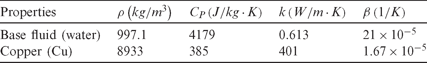
Fig. 1 presents the initial schematic diagram of the current physical models and their particle generation. The heated area with a high temperature Th is positioned at the center of the H-shaped enclosure with an equal variable length B. The other center walls and the horizontal walls are thermally insulated. The sidewalls of the H-shaped enclosure have a low-temperature Tc. H-cavity length is L = 1.4 and its height is W = 1.6. Center length and height of the H-shaped enclosure are LH = 0.4 and WH = 0.4, respectively. Model 2 shows the inner blockages with variable numbers inside an H-shaped enclosure. These blockages are maintained at a low temperature Tc with an initial zero velocity. The blockages are taken as square shapes with a length 0.1 and their positions are settled in the center of the H-shaped enclosure. Tab. 1 introduces the physical properties of the water as a base fluid and a copper as nanoparticles.
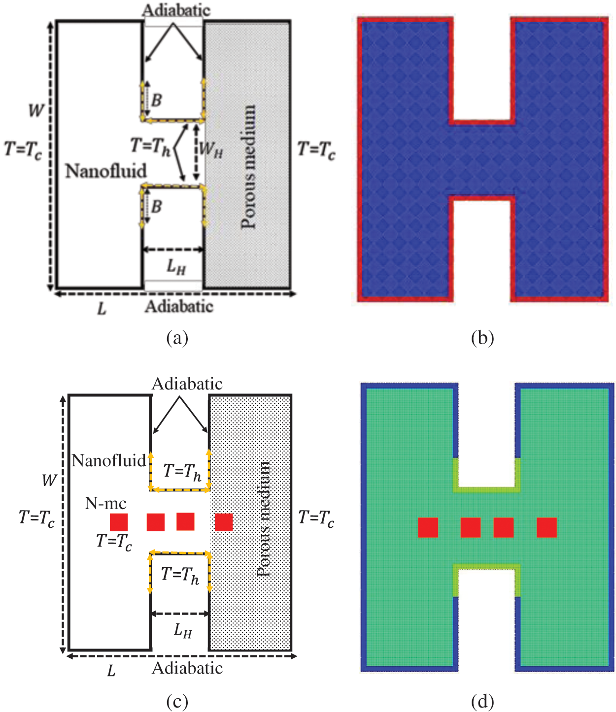
Figure 1: Initial physical models and their particles generations. (a) Initial physical model (1). (b) Particles (mesh) model (1). (c) Initial physical model (2). (d) Particles (mesh) model (2)
Table 1: Physical properties of the water and copper (Cu)
In this study, one phase model and Brinkman’s-extended non-Darcy model are used for a nanofluid and a porous medium, respectively. The Lagrangian form of governing equations are written as [35,36]:


where,

K and F are Forchheimer’s coefficient:

The properties of the nanofluid are defined as [37–40]:


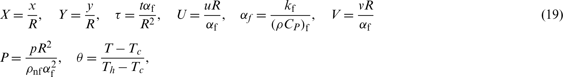
The Lagrangian form of the dimensionless equations are defined as:


The dimensionless quantities are:
In this study, the dimensionless boundary conditions are:
On the outer side-walls of H-cavity: 
On the center walls of H-cavity: 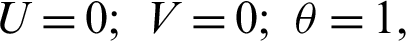
On the horizontal and center walls of H-cavity: 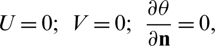
On the embedded square blockages: 
The average Nusselt number is defined as:

where  and Lw is the normal vector and total length of the heated partition in the H-cavity.
Here, the solving steps for the implicit scheme in the ISPH method are mainly depend in the projection method [41]. Prediction step:


where, 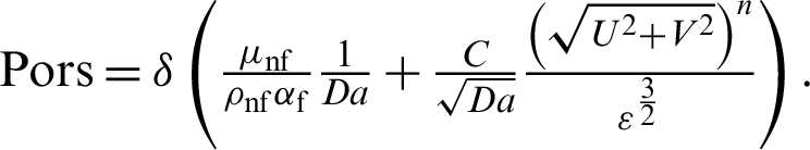
Pressure Poisson equations (PPE):

where,  is a relaxation parameter. Hyder et al. [42] used a new framework for solving
  -stochastic Poisson equation.
The corrector step:


Thermal equation:

Update the particles positions:


In this study, the shifting technique according to [43] is applied to avoid particles disorders:


where  is any hydrodynamic function and
  is a gradient of particle concentration.
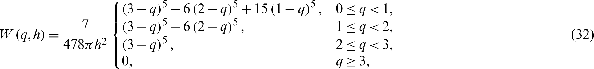
The concept of SPH method for calculating any fluid hydrodynamics properties is:

W is a kernel function:
The divergence and gradient in SPH method can be approximated as:


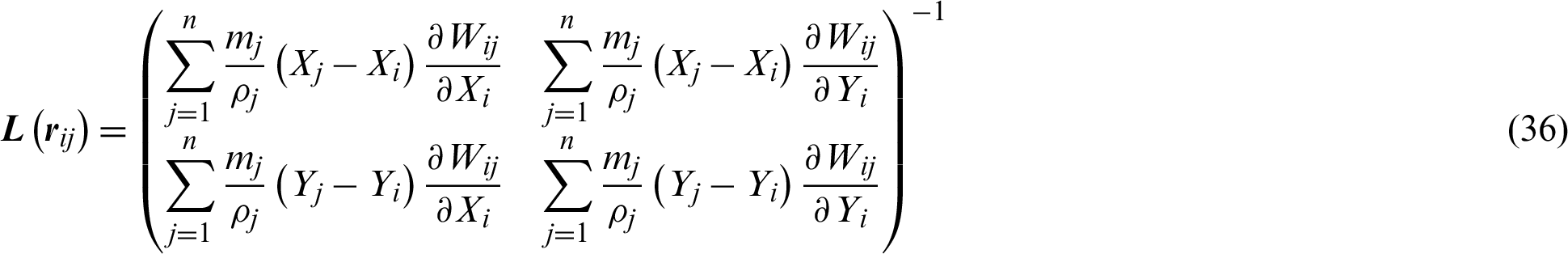
According to [44], the divergence of the velocity is corrected by a kernel gradient normalization as:

The gradient of the pressure and the divergence of the velocity vector are:


For the second derivative, Laplacian operator can be approximated as:

Laplacian of velocity, pressure and temperature are approximated as:


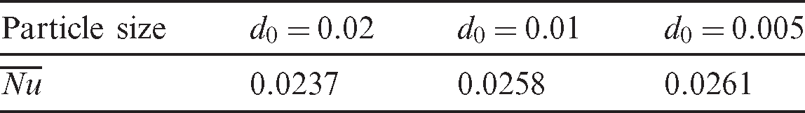
In order to prove the efficiency of the present ISPH method for simulating the natural convection flow in a partial layer porous cavity, a comparison of the temperature profiles along different horizontal lines with numerical and experimental data from Beckermann et al. [45] is performed. In Fig. 2, ISPH results for the temperature profiles at three different positions in a partial layer porous cavity are agreeing well with the available numerical and experimental data from Beckermann et al. [45]. For the mesh independence test, three different particle sizes d0 = 0.02, 0.01 and 0.005 were investigated. Tab. 2 presents the average Nusselt number for three different particle sizes d0 = 0.02, 0.01 and 0.005. There are small variations in the value of average Nusselt number at three different particle sizes. Hence, the particle size d0 = 0.01 has been chosen for all the performed simulations in the current study.
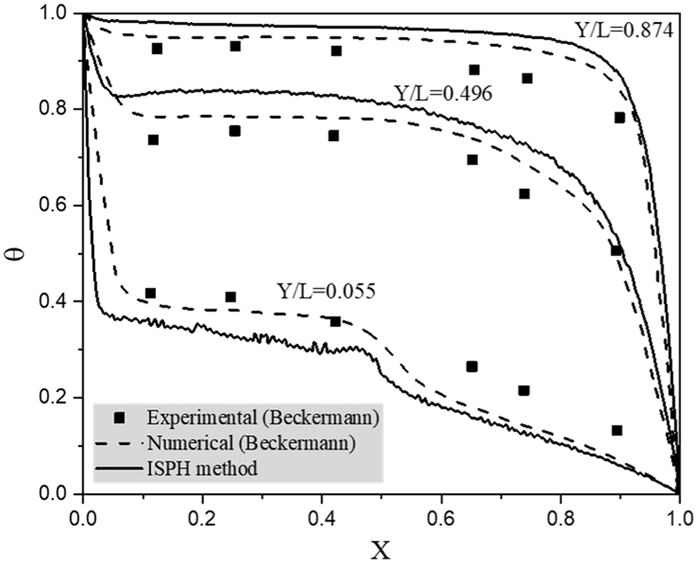
Figure 2: Comparison of the natural convection in a partitioned porous cavity between numerical and experimental data from Beckermann et al. [45] and present ISPH results
Table 2: Mesh independence test for average Nusselt number  when the hot source length B = 0.2, solid volume fraction
  .01, Rayleigh number Ra = 104, Darcy parameter Da = 10−3, and porosity
  .6
.6
In this work, the numerical simulations of the natural convection in an H-shaped enclosure under the impacts of the key physical parameters were presented in the temperature and velocity field distributions as well as average Nusselt number profiles. The partitions of the hot source in the center boundary of the H-shaped enclosure were varied from 0 to 0.6. Rayleigh number varies from 103 to 105 and the Darcy parameter varies from 10−2 to 10−5. Different numbers of the cooled square blockages inside an H-shaped enclosure were considered. In addition, adding more concentration of nanoparticles inside an H-shaped enclosure was limited on 5% to avoid the solidification between the nanoparticles and a porous medium. This section is divided into four parts depending on the impacts of the physical parameters and thermal conditions. The first part will discuss the presence of the cooled square blockages inside an H-shaped enclosure with variations on the number of cooled blockages. The second part will check the impacts of the variable length of the hot source. Third part will investigate the effects of the augmented buoyancy force (greater values of the Rayleigh number) with increasing the porous resistance (lower values of the Darcy parameter) on the right side of the H-shaped enclosure. Finally, an enhancement of heat transfer by adding more nanoparticles concentration will be discussed.
5.1 Presence of Cooled Blockages
Fig. 3 presents the temperature distributions under the variations on the number of the cooled square blockages at Rayleigh number Ra = 104, Darcy parameter Da = 10−3,  .01, porosity
  .6 and hot source length B = 0.2. It is found that the number of the cooled square blockages plays an important role in decreasing the temperature distributions inside an H-shaped enclosure. It is seen that the cooled square blockages are reducing the temperature distributions in the center of the H-shaped enclosure. An extra number of the cooled square blockages (around eight blockages) reduces the temperature distributions beside the hot source inside an H-shaped enclosure. Fig. 4 shows the velocity field distributions under the variations on the number of the cooled square blockages. In general, due to the porous resistance on the right side of the H-shaped enclosure, the velocity of the fluid flows on the right porous layer is lower than the velocity of the fluid flows on the left side (nanofluid layer) of the H-shaped enclosure. It seems that the velocity of the fluid flows is decreasing according to an increase in the number of the cooled square blockages. The time transitions from the unsteady state to steady-state for the temperature distributions under the variations on the number of the cooled square blockages have been shown in Fig. 5. An extra number of the cooled blockages reduces the temperature distributions.
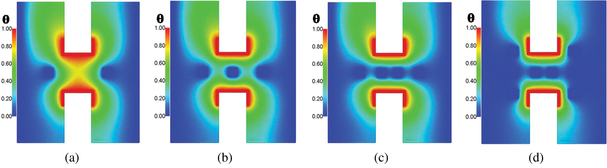
Figure 3: Temperature distributions under different numbers of the cooled square blockages at Rayleigh number Ra = 104, Darcy parameter Da = 10−3, 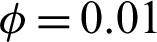 , porosity
  and hot source length B = 0.2. (a) Two blockages. (b) Three blockages. (c) Four blockages. (d) Eight blockages
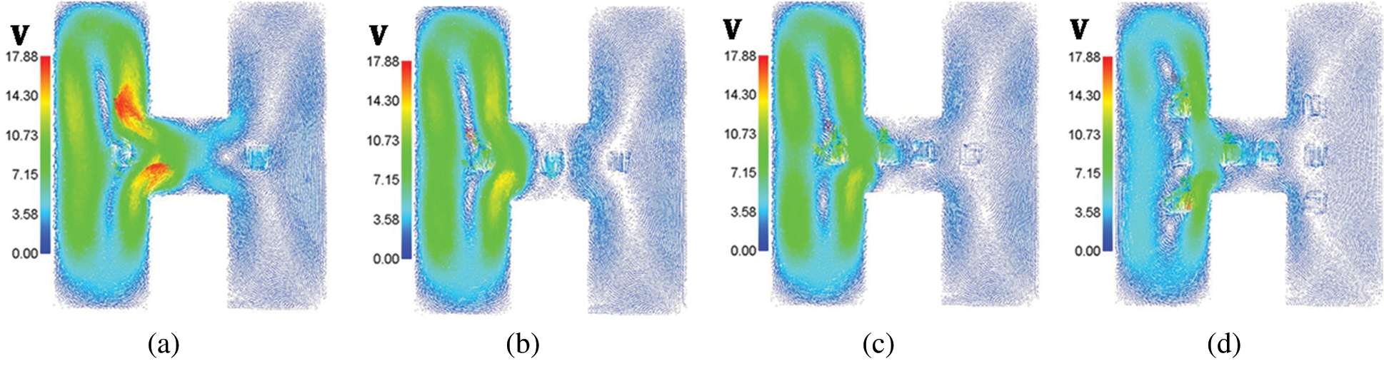
Figure 4: Velocity field distributions under different numbers of the cooled square blockages at Rayleigh number Ra = 104, Darcy parameter Da = 10−3,  , porosity
  and hot source length B = 0.2. (a) Two blockages. (b) Three blockages. (c) Four blockages. (d) Eight blockages
Figure 5: Time histories for the temperature distributions under different numbers of the cooled square blockages at Rayleigh number Ra = 104, Darcy parameter Da = 10−3,  .01, porosity
  and hot source length B = 0.2. (a) Two blockages. (b) Eight blockages
–-Effects of the Hot Source Length
Figs. 6 and 7 show the temperature distributions under the impacts of the hot length B at Rayleigh number Ra = 104, Darcy parameter Da = 10−3,  .01 and porosity
  .6. An increase on the length of the hot source augments the buoyancy force and consequently it rises the temperature distributions inside an H-shaped enclosure. When the length of the hot source is equal to 0.6, then the temperature distributions are fully filled out the both sides of the H-shaped enclosure. In addition, an increase in the length of the hot source augments the buoyancy force and consequently the velocities of the fluid flows inside an H-shaped enclosure are increasing. This behavior appears in Fig. 7, in which the velocity fields in both sides of the H-shaped enclosure are increasing according to an increase in the length of the hot source.
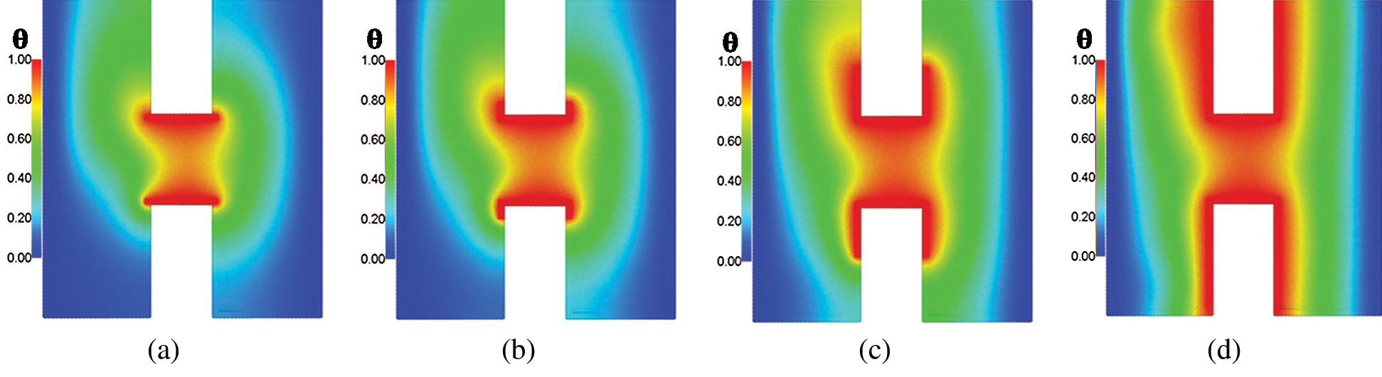
Figure 6: Temperature distributions under the impacts of hot source length B at Rayleigh number Ra = 104, Darcy parameter Da = 10−3,  and porosity
  . (a)
. (a)  . (b)
. (b) 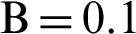 . (c)
. (c)  . (d)
. (d) 
Figure 7: Velocity field distributions under the impacts of hot source length B at Rayleigh number Ra = 104, Darcy parameter Da = 10−3,  and a porosity
  . (a)
. (a)  . (b)
. (b)  . (c)
. (c)  . (d)
. (d) 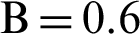
–-Effects of Rayleigh and Darcy Parameter
Figs. 8 and 9 introduce the influences of Rayleigh and Darcy parameter on the temperature and velocity field distributions at  .01, porosity
  and hot length B = 0.2. Generally, an increase in the Rayleigh number augments the buoyancy force and consequently both of the temperature distributions and strength of the velocity fields are increase. From Fig. 8, as the Darcy parameter decreases from Da = 10−2 to 10−5, the temperature distributions on the right side (porous layer) of the H-shaped enclosure are decreasing due to high porous resistance in this side for any value of Rayleigh number. Moreover, an increase on the Rayleigh number augments the temperature distributions and the physical reason returns to the high buoyancy force. From Fig. 9, there are clear differences in the velocity fields between the left and right area of the H-shaped enclosure due to the presence of the porous layer on the right side. Hence, as the Darcy parameter decreases (higher porous resistance) leads to a strong decrease on the velocity fields on the right side (porous layer) of the H-shaped enclosure.
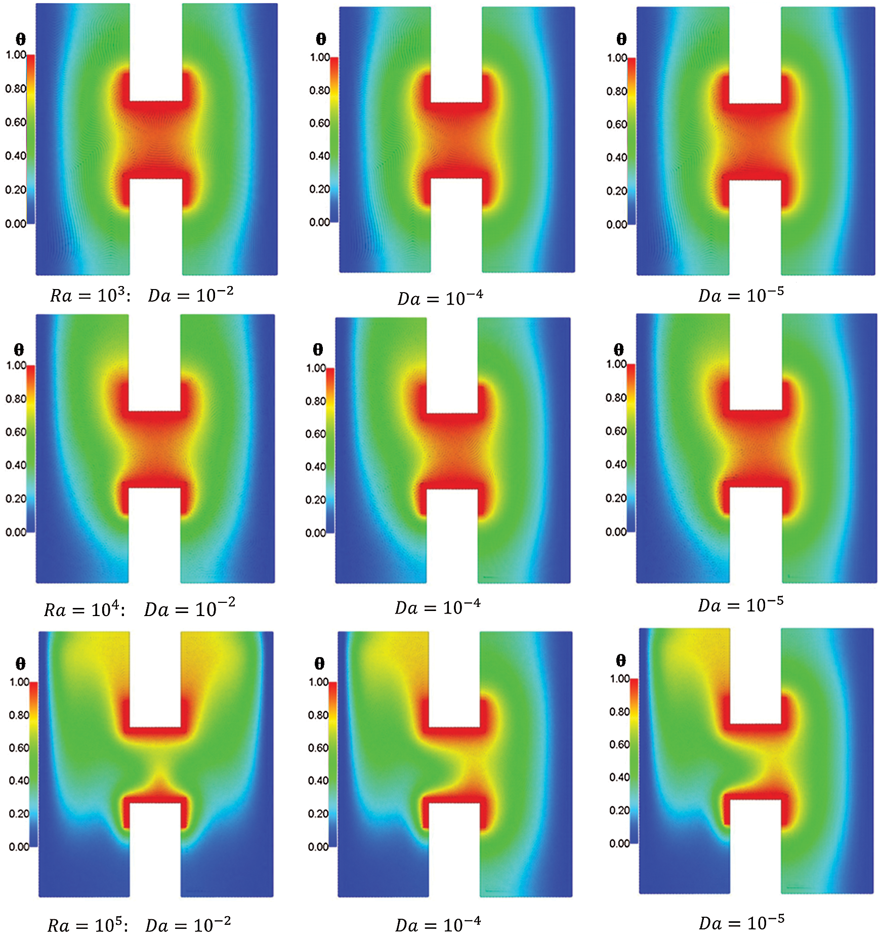
Figure 8: Effects of Rayleigh and Darcy parameter on the temperature distributions at  , porosity
  and hot length B = 0.2
Figure 9: Effects of Rayleigh and Darcy parameter on the velocity field distributions at  , porosity
  and hot length B = 0.2
Higher buoyancy force at higher Rayleigh number augments the strength of the velocity fields and the distributions of the velocity fields inside an H-shaped enclosure. It is seen that the maximum values of the velocity fields are 1.82, 15.79 and 84.31 when the Rayleigh number equals Ra = 103, 104 and 105, respectively. From these results, the Rayleigh number is considering the main factor in the enhancement of heat transfer and fluid flows inside an H-shaped enclosure. Fig. 10 presents the average Nusselt number under the impacts of Rayleigh and Darcy parameter at  .01, porosity
  .6 and hot length B = 0.2. It seems that the highest value of the average Nusselt number appears at Rayleigh number Ra = 105. As Darcy parameter rises from 10−5 to 10−2, the average Nusselt number decreases when Rayleigh number equals to Ra = 105. At lower values of the Rayleigh number
  , the average Nusselt number has slight changes under the impact of a Darcy parameter.
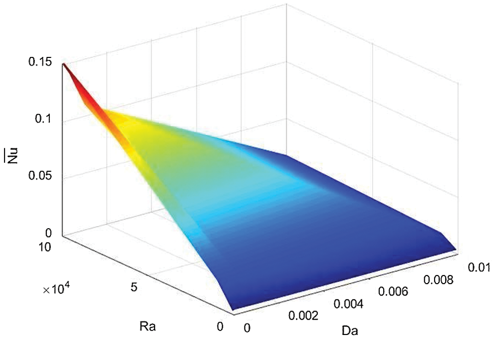
Figure 10: Effects of Rayleigh and Darcy parameter on the average Nusselt number at  , porosity
  and hot length
5.2 Effects of Solid Volume Fraction
Figs. 11 and 12 introduce the distributions of the temperature inside H-enclusre under the effects of solid volume fraction  at Rayleigh number Ra = 104, Darcy parameter Da = 10−3, porosity
  .6 and hot source length B = 0.2. In Fig. 11, an increase in the solid volume fraction
  enhances the temperature distributions. In Fig. 12, adding nanoparticles augments the viscosity of the fluid and consequently the velocity fields were declined. In the current simulations, adding nanoparticles is limited to 5% to avoid the solidification within the porous medium.
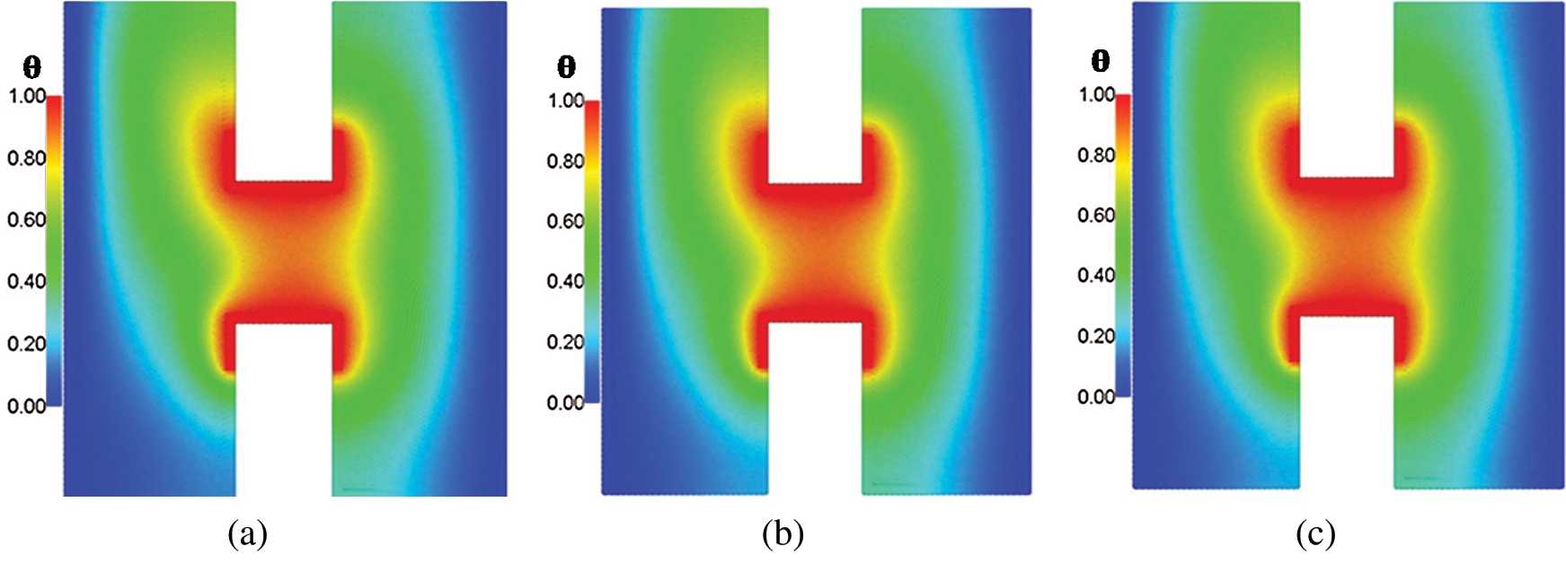
Figure 11: Temperature distributions under the effects of solid volume fraction  at Rayleigh number Ra = 104, Darcy parameter Da = 10−3, porosity
  and hot source length B = 0.2. (a)
  . (b)
. (b) 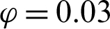 . (c)
. (c) 
Figure 12: Velocity fields distributions under the effects of solid volume fraction  at Rayleigh number Ra = 104, Darcy parameter Da = 10−3, porosity
  and hot source length B = 0.2. (a)
  , (b)
, (b)  , (c)
, (c) 
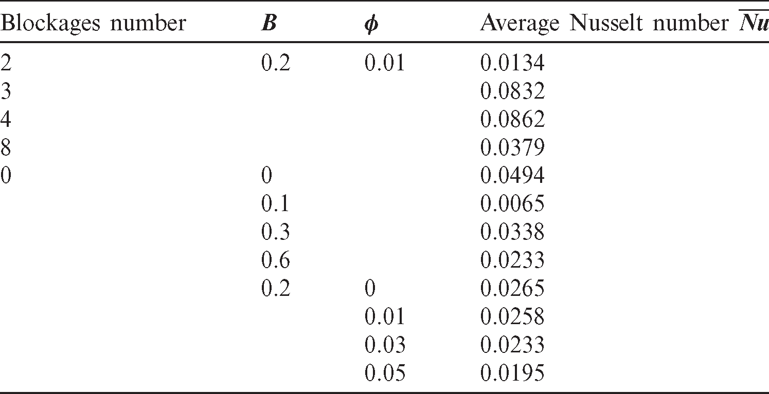
Tab. 3 presents the average Nusselt number  for different values of blockages numbers, hot source length B and solid volume fraction
  at Rayleigh number Ra = 104, Darcy parameter Da = 10−3 and porosity
  .6. Here, the average Nusselt number is varying as the number of the square blockages is increasing from 2 to 8. There is one peak in the average Nusselt number when the number of the square blockages is equal to four. The description of the peak is appeared when the number of blockages is increasing from two to four and from four to eight blockages. Average Nusselt number is decreasing as the length of the hot source B is increasing from 0 to 0.1. While, as B is increasing from 0.1 to 0.3, the average Nusselt number rises. There is a slight decrease on the average Nusselt number as the hot length B increases from 0.3 to 0.6. In addition, adding more concentration of the nanoparticles from 0 to 5% moderates the average Nusselt number.
Table 3: Average Nusselt number  for different values of blockages numbers, hot source length B and solid volume fraction
  at Rayleigh number Ra = 104, Darcy parameter Da = 10−3, and porosity
  .6
.6
The improved ISPH method presented in this paper is a simple approach to simulate the natural convection from the heated partitions in a nanofluid-filled H-shaped enclosure saturated with a partial layer porous medium. ISPH method is modified in terms of the solving pressure Poisson equation and corrected the first derivative of the velocity. The simulations showed that the length of the hot source augments the buoyancy force and consequently the distributions of the velocity field and temperature are increased. An extra number of the cooled square blockages reduces the distributions of the temperature and velocity field inside an H-shaped enclosure. The Rayleigh number plays an important factor in the augmentation of the velocity field and temperature distributions inside an H-shaped enclosure. Due to the porous resistance on the right side of the H-shaped enclosure, there is clear difference in the velocity field between the left and right sides of the H-shaped enclosure. As the Darcy parameter decreases, then there is almost no fluid flow inside the right side (porous layer) of the H-shaped enclosure. The average Nusselt number is increasing as the Rayleigh number increases and it declines according to an increase in Darcy parameter. Adding nanoparticles until 5% reduces the velocity field and enhances the heat transfer inside an H-shaped enclosure.
Acknowledgement: The authors would like to extend their appreciations to the Deanship of Scientific Research at King Khalid University, Abha, Saudi Arabia, for funding this work through the Research Group Project under Grant Number (R.G.P 2/70/41).
Funding Statement: Deanship of Scientific Research at King Khalid University, Abha, Saudi Arabia funded this work through project number (R.G.P 2/70/41).
Conflicts of Interest: The authors declare that they have no conflicts of interest to report regarding the present study.
1 R. W. Lewis and H. R. Ghafouri. (1997). “A novel finite element double porosity model for multiphase flow through deformable fractured porous media,” International Journal for Numerical and Analytical Methods in Geomechanics, vol. 21, pp. 789–816. [Google Scholar]
2 R. W. Lewis and B. A. Shrefler. (1998). The Finite Element Method in the Static and Dynamic Deformation and Consolidation of Porous Media, 2 ed., Chichester, England: Wiley, pp. 1–508. [Google Scholar]
3 M. H. Esfe, A. A. A. Arani, W. M. Yan and A. Aghaei. (2017). “Natural convection in T-shaped cavities filled with water-based suspensions of COOH-functionalized multi walled carbon nanotubes,” International Journal of Mechanical Sciences, vol. 121, pp. 21–32. [Google Scholar]
4 Z. Li, P. Barnoon, D. Toghraie, R. Balali Dehkordi and M. Afrand. (2019). “Mixed convection of non-Newtonian nanofluid in an H-shaped cavity with cooler and heater cylinders filled by a porous material: Two phase approach,” Advanced Powder Technology, vol. 30, no. 11, pp. 2666–2685. [Google Scholar]
5 S. Bhowmick, F. Xu, X. Zhang and S. C. Saha. (2018). “Natural convection and heat transfer in a valley shaped cavity filled with initially stratified water,” International Journal of Thermal Sciences, vol. 128, pp. 59–69. [Google Scholar]
6 S. Bhowmick, S. C. Saha, M. Qiao and F. Xu. (2019). “Transition to a chaotic flow in a V-shaped triangular cavity heated from below,” International Journal of Heat and Mass Transfer, vol. 128, pp. 76–86. [Google Scholar]
7 Y. Ma, R. Mohebbi, M. M. Rashidi and Z. Yang. (2018). “Simulation of nanofluid natural convection in a U-shaped cavity equipped by a heating obstacle: Effect of cavity’s aspect ratio,” Journal of the Taiwan Institute of Chemical Engineers, vol. 93, pp. 263–276. [Google Scholar]
8 A. Rahimi, M. Sepehr, M. J. Lariche, M. Mesbah, A. Kasaeipoor et al. (2018). “Analysis of natural convection in nanofluid-filled H-shaped cavity by entropy generation and heatline visualization using Lattice Boltzmann Method,” Physica E: Low-Dimensional Systems and Nanostructures, vol. 97, pp. 347–362. [Google Scholar]
9 M. Izadi, R. Mohebbi, D. Karimi and M. A. Sheremet. (2018). “Numerical simulation of natural convection heat transfer inside a shaped cavity filled by a mwcnt-Fe3O4/water hybrid nanofluids using LBM,” Chemical Engineering and Processing–-Process Intensification, vol. 125, pp. 56–66. [Google Scholar]
10 S. E. Ahmed, M. A. Mansour, A. M. Alwatban and A. M. Aly. (2020). “Finite element simulation for MHD ferro-convective flow in an inclined double-lid driven L-shaped enclosure with heated corners,” Alexandria Engineering Journal, vol. 59, no. 1, pp. 217–226. [Google Scholar]
11 R. Mohebbi, M. Izadi, H. Sajjadi, A. A. Delouei and M. A. Sheremet. (2019). “Examining of nanofluid natural convection heat transfer in a -shaped enclosure including a rectangular hot obstacle using the Lattice Boltzmann Method,” Physica A: Statistical Mechanics and Its Applications, vol. 526, 120831. [Google Scholar]
12 X. Liu, H. Zhang, C. Zhu, F. Wang and Z. Li. (2019). “Effects of structural parameters on fluid flow and heat transfer in a serpentine microchannel with fan-shaped reentrant cavities,” Applied Thermal Engineering, vol. 151, pp. 406–416. [Google Scholar]
13 A. Purusothaman and E. H. Malekshah. (2019). “Lattice Boltzmann modeling of MHD free convection of nanofluid in a V-shaped microelectronic module,” Thermal Science and Engineering Progress, vol. 10, pp. 186–197. [Google Scholar]
14 Y. Ma, R. Mohebbi, M. M. Rashidi, Z. Yang and M. Sheremet. (2020). “Nanoliquid thermal convection in I-shaped multiple-pipe heat exchanger under magnetic field influence,” Physica A: Statistical Mechanics and its Applications, vol. 550, pp. 124028. [Google Scholar]
15 A. M. Aly. (2017). “Natural convection over circular cylinders in a porous enclosure filled with a nanofluid under thermo-diffusion effects,” Journal of the Taiwan Institute of Chemical Engineers, vol. 70, pp. 88–103. [Google Scholar]
16 M. Asai, A. M. Aly, Y. Sonoda and Y. Sakai. (2012). “A stabilized incompressible SPH method by relaxing the density invariance condition,” Journal of Applied Mathematics, vol. 2012, no. 3, pp. 1–24. [Google Scholar]
17 A. M. Aly and M. Asai. (2015). “Modelling of non-Darcy flows through porous media using extended incompressible smoothed particle hydrodynamics,” Numerical Heat Transfer, Part B: Fundamentals, vol. 67, no. 3, pp. 255–279.
18 A. M. Aly and M. Asai. (2015). “Three-dimensional incompressible smoothed particle hydrodynamics for simulating fluid flows through porous structures,” Transport in Porous Media, vol. 110, no. 3, pp. 483–502.
19 A. M. Aly, M. Asai and A. J. Chamkha. (2015). “Analysis of unsteady mixed convection in lid-driven cavity included circular cylinders motion using an incompressible smoothed particle hydrodynamics method,” International Journal of Numerical Methods for Heat & Fluid Flow, vol. 25, no. 8, pp. 2000–2021.
20 M. T. Nguyen, A. M. Aly and S. W. Lee. (2017). “Effect of a wavy interface on the natural convection of a nanofluid in a cavity with a partially layered porous medium using the ISPH method,” Numerical Heat Transfer, Part A: Applications, vol. 72, no. 1, pp. 68–88.
21 A. Khayyer, H. Gotoh, H. Falahaty and Y. Shimizu. (2018). “An enhanced ISPH–SPH coupled method for simulation of incompressible fluid-elastic structure interactions,” Computer Physics Communications, vol. 232, pp. 139–164.
22 S. Shao. (2010). “Incompressible SPH flow model for wave interactions with porous media,” Coastal Engineering, vol. 57, no. 3, pp. 304–316. [Google Scholar]
23 E. Kazemi, K. Koll, S. Tait and S. Shao. (2020). “SPH modelling of turbulent open channel flow over and within natural gravel beds with rough interfacial boundaries,” Advances in Water Resources, vol. 140, 10355. [Google Scholar]
24 E. Kazemi, S. Tait and S. Shao. (2020). “SPH-based numerical treatment of the interfacial interaction of flow with porous media,” International Journal for Numerical Methods in Fluids, vol. 92, no. 4, pp. 219–245. [Google Scholar]
25 S. E. Ahmed and A. M. Aly. (2019). “Natural convection in a nanofluid-filled cavity with solid particles in an inner cross shape using ISPH method,” International Journal of Heat and Mass Transfer, vol. 141, pp. 390–406. [Google Scholar]
26 A. M. Aly, Z. Raizah and M. Asai. (2019). “Natural convection from heated fin shapes in a nanofluid-filled porous cavity using incompressible smoothed particle hydrodynamics,” International Journal of Numerical Methods for Heat & Fluid Flow, vol. 29, no. 12, pp. 4569–4597. [Google Scholar]
27 Z. Raizah and A. M. Aly. (2019). “Natural convection from heated shape in nanofluid-filled cavity using incompressible smoothed particle hydrodynamics,” Journal of Thermophysics and Heat Transfer, vol. 33, no. 4, pp. 917–931.
28 A. M. Aly, Z. A. S. Raizah and M. Sheikholeslami. (2020). “Analysis of mixed convection in a sloshing porous cavity filled with a nanofluid using ISPH method,” Journal of Thermal Analysis and Calorimetry, vol. 139, no. 3, pp. 1977–1991.
29 A. M. Aly and Z. Raizah. (2019). “Mixed convection in an inclined nanofluid filled-cavity saturated with a partially layered porous medium,” Journal of Thermal Science and Engineering Applications, vol. 11, 41002.
30 Z. A. Raizah and A. M. Aly. (2019). “ISPH method for MHD double-diffusive natural convection of a nanofluid within cavity containing open pipes,” International Journal of Numerical Methods for Heat & Fluid Flow, vol. 30, no. 7, pp. 3607–3634.
31 A. M. Aly and Z. A. S. Raizah. (2019). “Incompressible smoothed particle hydrodynamics method for natural convection of a ferrofluid in a partially layered porous cavity containing a sinusoidal wave rod under the effect of a variable magnetic field,” AIP Advances, vol. 9, pp. 105210.
32 A. M. Aly and Z. A. S. Raizah. (2019). “Coupled fluid-structure interactions of natural convection in a ferrofluid using ISPH method,” Alexandria Engineering Journal, vol. 58, no. 4, pp. 1499–1516.
33 A. M. Aly and Z. A. S. Raizah. (2020). “Incompressible smoothed particle hydrodynamics simulation of natural convection in a nanofluid-filled complex wavy porous cavity with inner solid particles,” Physica A: Statistical Mechanics and Its Applications, vol. 537, pp. 122623.
34 A. M. Aly and S. E. Ahmed. (2020). “ISPH simulations for a variable magneto-convective flow of a ferrofluid in a closed space includes open circular pipes,” International Communications in Heat and Mass Transfer, vol. 110, 104412. [Google Scholar]
35 M. T. Nguyen, A. M. Aly and S. W. Lee. (2017). “Effect of a wavy interface on the natural convection of a nanofluid in a cavity with a partially layered porous medium using the ISPH method,” Numerical Heat Transfer, Part A: Applications, vol. 72, no. 1, pp. 68–88. [Google Scholar]
36 M. T. Nguyen, A. M. Aly and S. W. Lee. (2018). “ISPH modeling of natural convection heat transfer with an analytical kernel renormalization factor,” Meccanica, vol. 53, no. 9, pp. 2299–2318. [Google Scholar]
37 A. M. Rashad, M. M. Rashidi, G. Lorenzini, S. E. Ahmed and A. M. Aly. (2017). “Magnetic field and internal heat generation effects on the free convection in a rectangular cavity filled with a porous medium saturated with cu-water nanofluid,” International Journal of Heat and Mass Transfer, vol. 104, pp. 878–889. [Google Scholar]
38 S. E. Ahmed and H. M. Elshehabey. (2018). “Buoyancy-driven flow of nanofluids in an inclined enclosure containing an adiabatic obstacle with heat generation/absorption: Effects of periodic thermal conditions,” International Journal of Heat and Mass Transfer, vol. 124, pp. 58–73.
39 A. M. Aly, Z. A. S. Raizah and S. E. Ahmed. (2018). “Natural convection in an enclosure saturatedwith multilayer porous medium and nanofluid over circular cylinders: entropy generation,” Journal of Porous Media, vol. 21, no. 1, pp. 1–10.
40 A. M. Aly and Z. A. S. Raizah. (2019). “Mixed convection in an inclined nanofluid filled-cavity saturated with a partially layered porous medium,” Journal of Thermal Science and Engineering Applications, vol. 11, no. 4, 041002. [Google Scholar]
41 S. J. Cummins and M. Rudman. (1999). “An SPH projection method,” Journal of Computational Physics, vol. 152, no. 2, pp. 584–607. [Google Scholar]
42 A. A. Hyder and M. Zakarya. (2016). “Non-gaussian wick calculus based on hypercomplex systems,” International Journal of Pure and Applied Mathematics, vol. 109, pp. 539–556. [Google Scholar]
43 R. Xu, P. Stansby and D. Laurence. (2009). “Accuracy and stability in incompressible SPH (ISPH) based on the projection method and a new approach,” Journal of Computational Physics, vol. 228, no. 18, pp. 6703–6725. [Google Scholar]
44 J. Bonet and S. Kulasegaram. (2000). “Correction and stabilization of smooth particle hydrodynamics methods with applications in metal forming simulations,” International Journal for Numerical Methods in Engineering, vol. 47, pp. 1189–1214. [Google Scholar]
45 C. Beckermann, S. Ramadhyani and R. Viskanta. (1987). “Natural convection flow and heat transfer between a fluid layer and a porous layer inside a rectangular enclosure,” Journal of Heat Transfer, vol. 109, no. 2, pp. 363–370. [Google Scholar]
 | This work is licensed under a Creative Commons Attribution 4.0 International License, which permits unrestricted use, distribution, and reproduction in any medium, provided the original work is properly cited. |