DOI:10.32604/cmc.2020.012580
| Computers, Materials & Continua DOI:10.32604/cmc.2020.012580 | |
| Article |
Design and Implementation of Wheel Chair Control System Using Particle Swarm Algorithm
1Mechanical Engineering Department, College of Engineering, King Abdulaziz University, Jeddah, 21589, Saudi Arabia
2Electrical and Computer Engineering, College of Engineering, King Abdulaziz University, Jeddah, 21589, Saudi Arabia
3Mechanical Engineering Department, College of Engineering, Taif University, Taif, 21944, Saudi Arabia
*Corresponding Author: Ayman A. Aly. Email: draymanelnaggar@gmail.com
Received: 05 July 2020; Accepted: 12 August 2020
Abstract: About 10–20% of every country’s population is disable. There are at least 650 million people with a kind of disability worldwide. Assistance and support are perquisites for many handicap people for participating in society. Electric powered wheelchairs provide efficient mobility to motor impaired persons. In this paper a smart controller of a wheel chair mobile robot using Particle Swarm Optimization Proportional controller (PSO-P) was proposed where (PSO) algorithm was utilized to tune the proportional controller’s gains for each axis. Aiming to improve wheelchair tracking trajectory, a kinematic model of a robot with linear and angular velocities parameters was developed. The controller performance was examined using the system parameters with respect to trajectory references. A simulation of the proposed controller showed good correlation of the trajectory track under different loading conditions.
Keywords: PSO; mobile robot; trajectory tracking; tracking control
Nomenclature
| cij | center parameters of the MFs |
| E(i) | cost functions for ith particle |
| e1(i) | 1st joint error |
| e2(i) | 2nd joint error |
| F | generalized force. |
| gbest | global best position of particle |
| Ic | chair moment of inertia. |
| ith | particle sample |
| Im | wheel and motor moment of inertia around the wheel diameter. |
| Iw | wheel and motor moment of inertia around the wheel axis. |
| j | iteration number. |
| Kp1 | control gain of axis1 |
| Kp2 | control gain of axis2 |
| l | vector position of wheel chair frame and reference frame |
| L | Lagrange function |
| MAE | magnitude of the error |
| mc | mass the chair only. |
| mw | wheel and motor mass. |
| N | sample number |
| pbest | best position of particle |
| pi | ith particle position |
| q | generalized coordinates |
 | kinematic energy of wheel chair |
| tf | final time |
| TwL | left axis kinematic. |
| TwR | right axis kinematic. |
| V | potential energy of wheel chair |
| vi | ith particle velocity |
| vL | left wheel velocity |
| vR | right wheel velocity |
| (XI ; YI) | motion reference frame |
| (XR; YR) | wheel chair frame |
| θ | angular position of wheel chair frame and reference frame |
 1 1 | speed of axis1 |
 2 2 | speed of axis2 |
| ω | system angular velocity |
| σij | deviation parameters of the MFs |
 | kinematic model for the wheel chair |
In Saudi Arabia, about 800,000 of the population suffer from moving disability. 100,000 of those are with extreme disability conditions [1]. According to the World Bank Organization 1 billon of the world population has some sort of disability. About 15% of those suffer significant disability conditions. This shows the importance of equipment and devices that are designed to deal with disabled people. In lack of such devices, social, economic conditions and important life matters interrupt severally. Electric wheelchair can ease such interruption where patents and alders can use it independently in their mobility. Electric carts are also becoming popular in tasks that are dangerous or troublesome for humans. It can replace workers in wide range of environments starting from factories to military and space exploration missions. Controllers differ with the verities of applications of carts. For instance, specifications of a warehouse trajectory are different than the trajectory of a warzone where maneuvering is needed to be precise. Such differences can be accumulated in the design of the controller.
The effort of improving electric wheelchairs and carts control is continually developed by researchers. In Emam et al. [2–4] developed controllable dynamic models. In [5] a model that considers the incline surface was proposed. Kirby et al. [6,7] considered stability in their model and its effect in performance and handling. Brown et al. [8] produced a PID control that is currently an industry standard for joy-stick controls of electric powered mobile chairs where it provides better management, handling and control overall.
Although the classical controllers have gained widespread usage across technological industries, it must also be pointed out that the unnecessary mathematical rigorosity, preciseness and accuracy involved with the design of controllers have been a major drawback. Designing and tuning a conventional controller appears to be conceptually intuitive, but can be hard in practice, if multiple objectives are to be achieved [9]. However, it is quite difficult to determine its optimum gains where systems are usually non-linear. Non-conventional control methods have been used to select the optimum desired motion of a controlled system where the minimal settling time with no overshoot is needed [10].
In this paper, proportional (P) controller tuning is attempted using the PSO algorithm which was introduced by Kennedy et al. [11]. The main advantage of this algorithm; it does not require detailed mathematical description of the process and finds the best possible control parameters based on the fitness function provided to guide the algorithm. A detailed study is presented with a PSO-P algorithm using various inertia weights.
The purpose of the research is to achieve a good control trajectory performance in terms of the system error and robustness for the system uncertainties. In this article, the dynamic model of the wheelchair will be introduced in Section 2. Then A PSO-P control strategy is suggested in Section 3. After that the PSO-adjusting policy for the P-control is illustrated in Section 4. Finally the results and conclusion are described in last Sections of 5 and 6.
The wheel chair as shown in Fig. 1 has 2 axes wheels. The center between the 2 axes is point P, the distance from point P to each wheel is l, θ is the angular position between wheel chair frame (XR; YR) and reference frame (XI; YI). Also r, l, θ, and  and
and  are the speeds of the 2 axes.
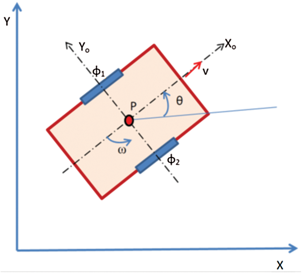
Figure 1: Wheel chair model
To perform the controlled movement of the wheel chair, the dynamic model of the system should be known. The Lagrange dynamic approach is showed systematically derives the equations of system motion [12,13].
Lagrange is a popular formulating approach for the governing equations of wheel chair motion. The general Lagrange equation is introduced by (1):
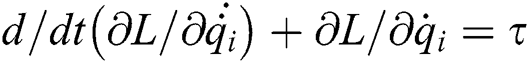
where: 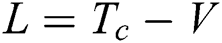 ; T is the kinematic energy of wheel chair; V is the potential energy; F is the generalized force.
The generalized coordinates q is chosen as:

The kinetic energy is formulated as:
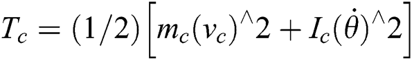
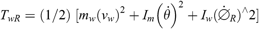

where
TwR: The right axis kinematic.
TwL: The left axis kinematic.
mc: The mass of the chair only.
mw: The wheel and motor mass.
Ic: The chair moment of inertia.
Iw: The wheel and motor moment of inertia around the wheel axis.
Im: The wheel and motor moment of inertia around the wheel diameter.
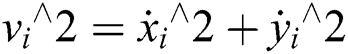
The axes velocities are formulated as:
The coordinates of wheels can be presented as:


From (3) to (8) overall kinematic energy of the system can be formulated as:

The wheeled chair moves on a horizontal level which is described by the position of the mobile chair and the angular difference [14].
The rotation matrix of the chair position is formulated as:
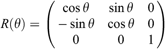
This rotation matrix describes the motion reference frame {XI; YI} to local frame {XR; YR}. The velocity of each driving wheel in the system can be the average of the left and right wheel velocities.

Also the system angular velocities:

Gathering the previous formulas, a kinematic model for the wheel chair can formulated as:
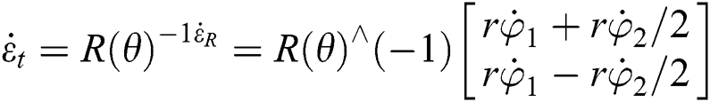
It is supposed  is always zero because there is no sideways motion.
The traditional method for finding the optimum tuning of control system parameters is to optimize the system model for each parameter and decide the characteristics of the system which give local optimum solution. This method may lead to solutions far away from the optimum as the method strongly depends on the peculiarities of the system and the intuition of the modeler. Thus, different approaches to optimize the control system to find global optimum solution are needed.
Aly [15] implemented the Genetic Algorithm (GA) to optimize PID parameters. The controller was verified on the state space model of servovalve attached to a rotary hydraulic actuator which is highly nonlinear dynamic system. The appropriate specifications of the GA for the rotary position control of an actuator system were presented. It is found that the optimal values of the feedback gains can be obtained within 10 generations, which corresponds to about 200 experiments. Also this strategy was verified again to optimize the control parameters of fire tube boiler [16]. The effect and violability of the Genetic-PID (GPID) control system and comparison with conventional control methods such as PID were investigated by nonlinear dynamic model simulation. In another challenge, the tuning of PD controller parameters for handling rigid spatial manipulators using GA was presented in [17]. A new fitness function was implemented to optimize the feedback gains and its efficiency was verified for control such nonlinear coupled system.
Compared with GAs, the information sharing mechanism in PSO is significantly different. In GAs, chromosomes share information with each other. So the whole population moves like a one group towards an optimal area [16]. In PSO, only gbest gives out the information to others. It is a one -way information sharing mechanism. The evolution only looks for the best solution. Compared with GA, all the particles tend to converge to the best solution quickly even in the local version in most cases.
In this study, the control design has two steps. The first step is finding the P controller gains using PSO algorithm which is search algorithms. The second step is applying the designed P to the wheel chair system with different trajectories references to grantee the stability and vanish the error of the system. Fig. 2 illustrates the system structure. The proposed control calculates the desired velocity (vd), angular velocity (ωd) according to the required position of the trajectory. The desired velocities (vd), and (ωd) will be the input to wheel chair dynamics which will use those values to produce the final velocities (v) and (ω) signals. In the next section, the P gains will be determined using PSO algorithm. In this section, PSO strategy is as shown in Fig. 3 to design P control parameters for a two axis robot to follow the reference trajectory.
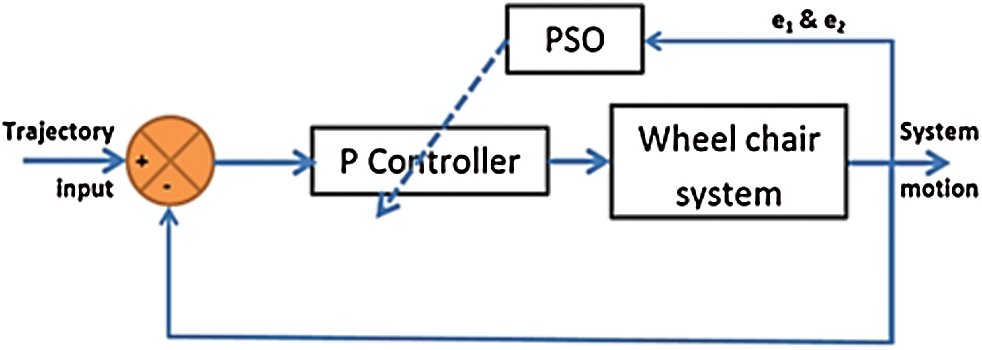
Figure 2: The overall system
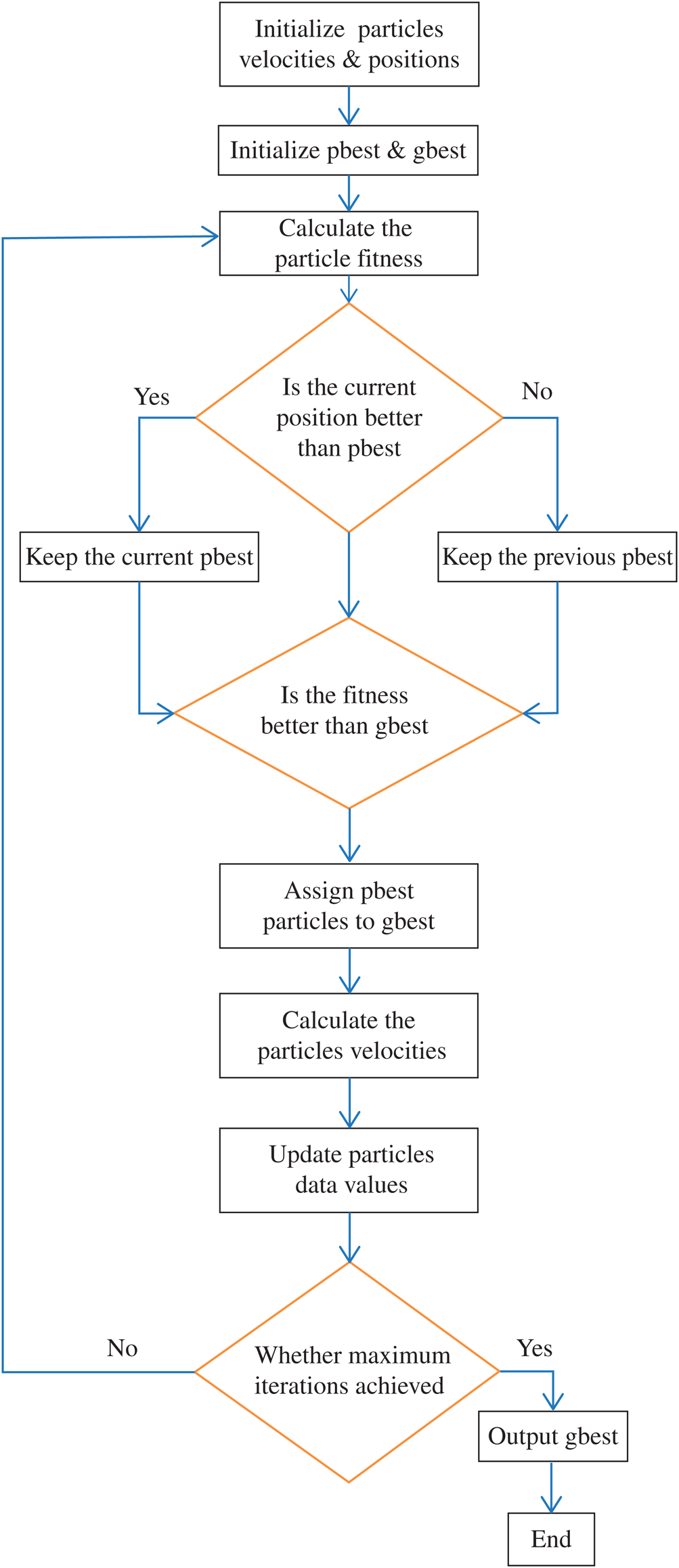
Figure 3: Flow diagram illustrating the PSO algorithm
3.1 Particle Swarm Optimization
Developmental computational strategy is dependent on the development and insight of multitudes searching for the most fertile feeding location. A “swarm” is an obviously disrupted assortment (populace) of moving individual that will in general bunch together while every individual is by all accounts moving an irregular way. It utilizes various specialists (particles) that establish a swarm moving around in the quest space searching for the best arrangement [12]. Each particle is handled as a point in an n-dimensional space which modifies its “flying” as per its own flying experience just as the flying experience of different particles. Every molecule monitors its directions in the issue space which are related with the best arrangement (fitness) that has accomplished up until now. This value is pbest. Another best value that is followed by the PSO is the best value got so far by any particle in the neighbors of the particle. This value is gbest [13,14].
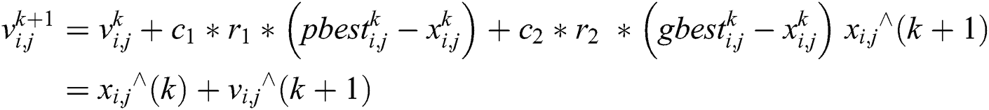
The PSO idea comprises of variation the speed (or its rate) of each particle toward its pbest and the gbest position at each time step. Every particle attempts to adjust its present position and speed as per the distance between its present position and pbest, and the distance between its present position and gbest as demonstrated the following. At every progression n, by utilizing the individual best position, pbest, and global best position, gbest, a new speed for the ith particle is refreshed.
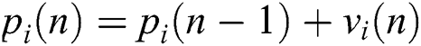
The speed is restricted to the scope of [−vmax, +vmax]. On the off chance that the speed disregards these cutoff points, it is compelled to its appropriate values. Changing speed by along these lines empowers the ith particle to look for its topical best position, pbest, and global best position, gbest. In light of the refreshed speed, every particle updates its situation as:
In Fig. 4a, the particle position trip during the iteration process for Kp1 of the first control axis while in Fig. 4b for the particle of second control axis Kp2.
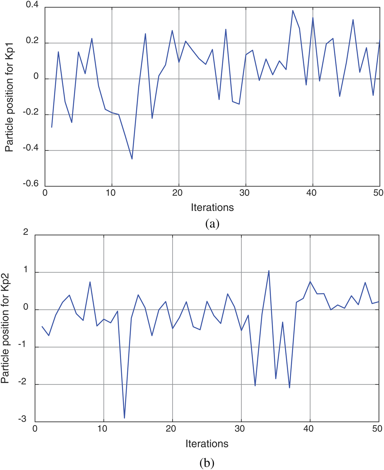
Figure 4: The particle position trip during the iteration process: (a) for Kp1; (b) for Kp2
Fig. 5a shows the particle velocity trip during the iteration process for Kp1 of the first control axis and Fig. 5b shows for the particle of second control axis Kp2. It ought to be noticed that the estimations of an element in the particle may surpass its sensible range. This calculation is continued until most extreme cycle is attainable as illustrated in Fig. 6.
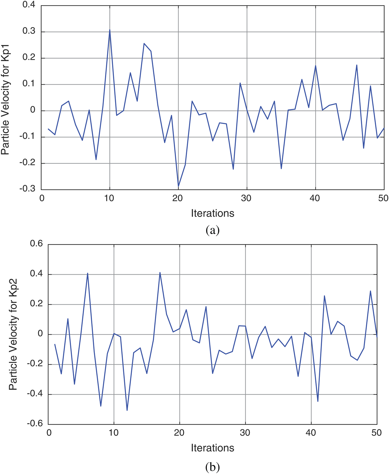
Figure 5: The particle velocity trip during the iteration process: (a) for Kp1; (b) for Kp2
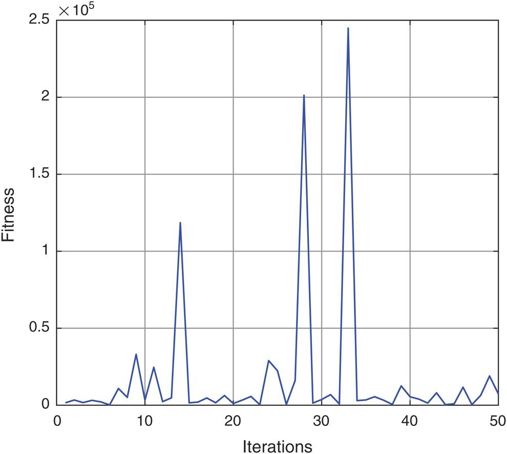
Figure 6: Fitness magnitude of the error (MAE)
PSO look through the entirety of the forerunner and resulting parameters in 50 dimensional spaces. The order of a particle is illustrated as:

where the σij and cij represent the center and deviation parameters of the MFs. The underlying estimations of particles are haphazardly created in the first generation.
The important step in implementing PSO is to find the best fitness function which is utilized to estimate cost of every particle. While adjusting steps is running with PSO, Magnitude of the Error (MAE) is utilized as a cost function, which is illustrated in Fig. 6. The cost functions for ith particle are calculated as:
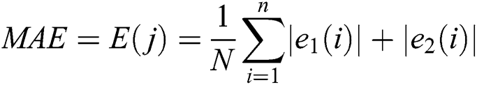
where e1(i) is the 1st joint error, e2(i) is the 2nd joint error of ith sample, N is the sample number, j is the iteration number.
The population size is chosen to be 10 particles for each axis for minimizing calculations effort, the cost function is computed for each particle and pbest and gbest are calculated for each final time (tf). A particle speed is computed for every particle and a particle position as follows:
To illustrate the system behavior under the proposed controller several standard test commands such as fixed point, line, and circle inputs are applied to the system. The responses of PSO-P controller are illustrated below. The performance of the control system through a set of simulations was examined. The values of kp1, and kp2, are found by PSO strategy.
For testing the controller performance, different three dynamic loads are used from references of [18–21] with different loads of 10 kg, 55 kg and 125 kg respectively. The control was designed based on the dynamics of a Pioneer 2-DX wheel chair [13] weighing of 10 kg. Then the system performance was examined two times by change the dynamic load of the system to be 55 kg and 125 kg, which changes its dynamics behavior from that of the Pioneer 2-DX significantly.
In the simulation, the mobile chair reaches fixed point from its original position, while another test is starting from its original position and moving to be closed with reference line and final test that the robot should follow a circular trajectory of reference.
Fig. 7 illustrates the response of the wheel chair system based on PSO-P for a reference fixed point input with test conditions of max linear velocity acceleration in both axis are 0.9 m/s and 0.5 m/s2 while max rotation velocity of 1.9 rad/s. The obtained results for fixed point of (1.0 m, 1.0 m) has settling time about of (54 s for payload of 10 and 55 kg) while for the dynamic load of 125 kg the settling time increased. The steady state error changed from about zero second to be 0.066 m when the dynamics parameters of payload of 125 kg was implemented as presented in Fig. 8. The Cartesian components of polar trajectory were illustrated at Figs. 9a, 9b with steady state error in X axis is approximately 0.05 m and in y axis 0.043 m while the velocities were illustrated in Figs. 10a, 10b for both of linear and rotary under the maximum designed values.
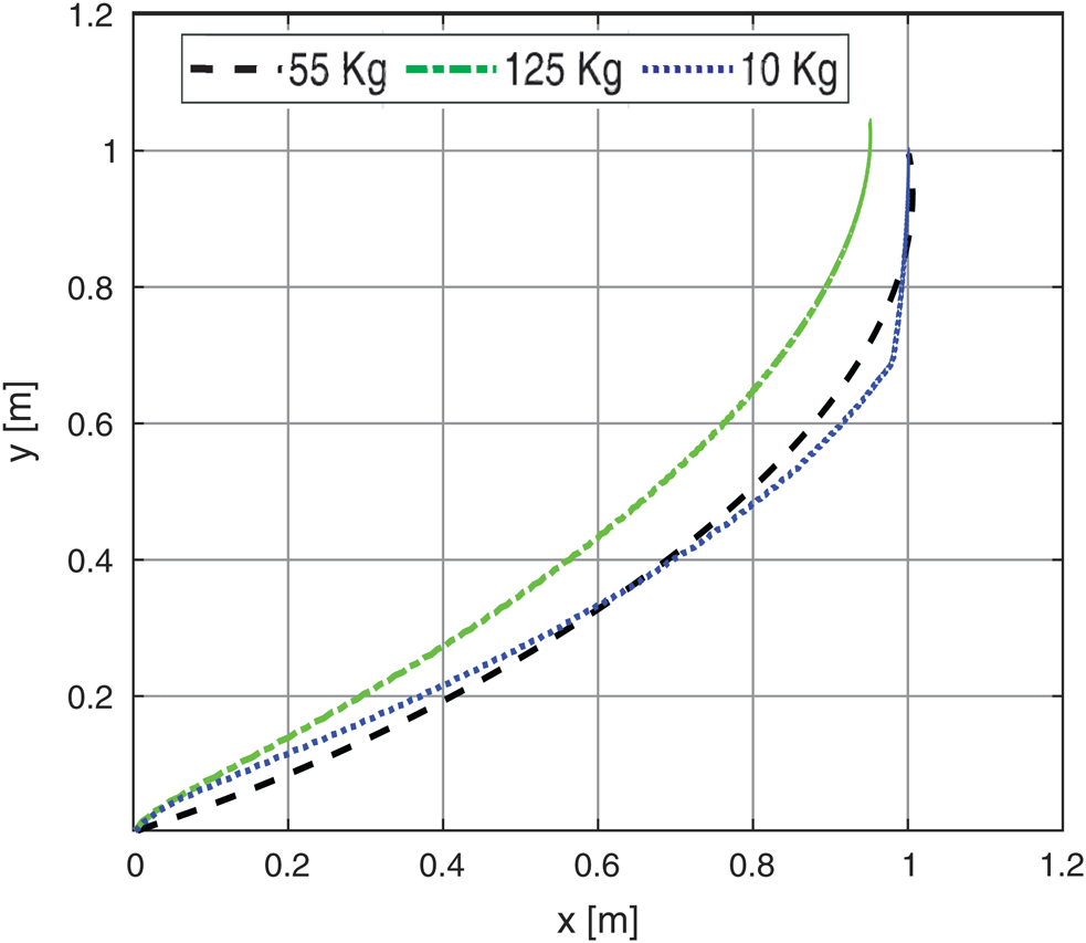
Figure 7: The system response based on fixed point reference with different payloads
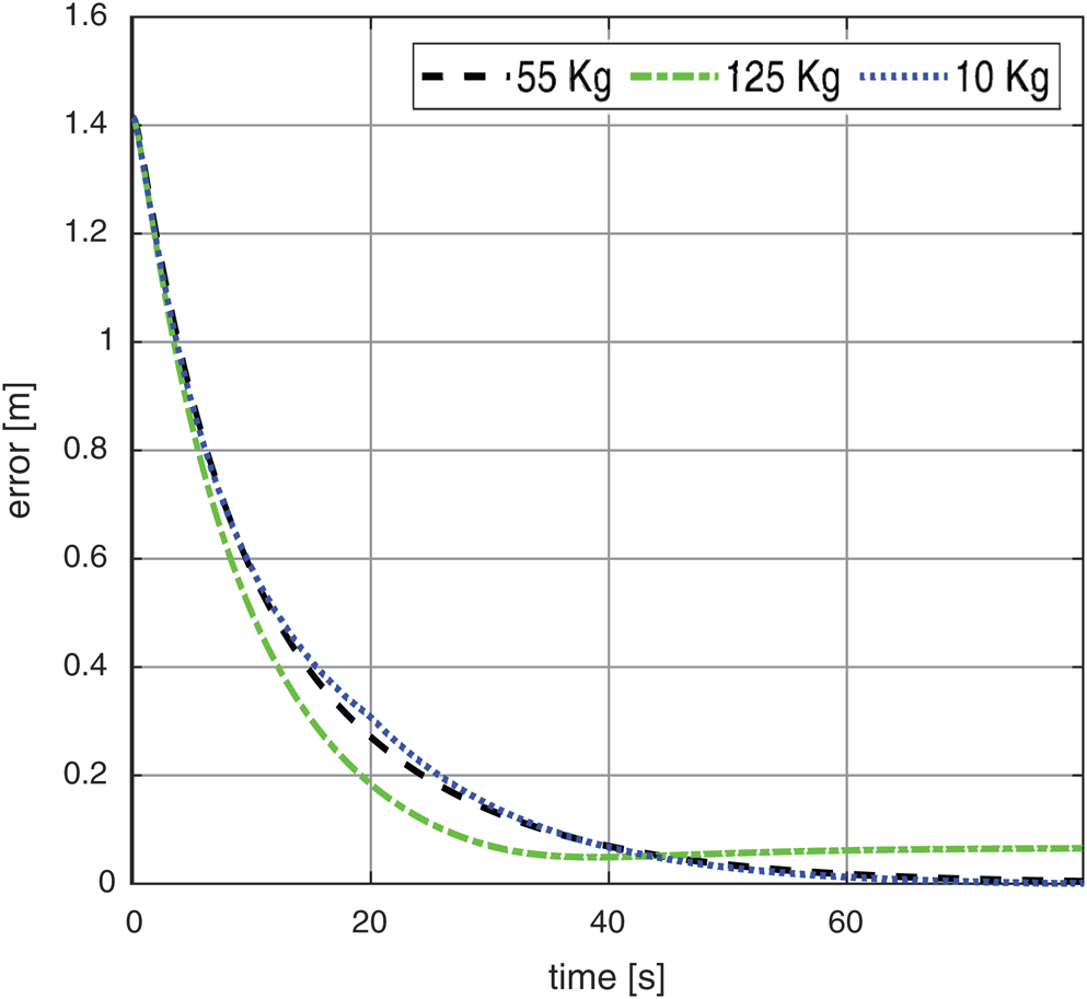
Figure 8: The system response error based on fixed point reference with different payloads
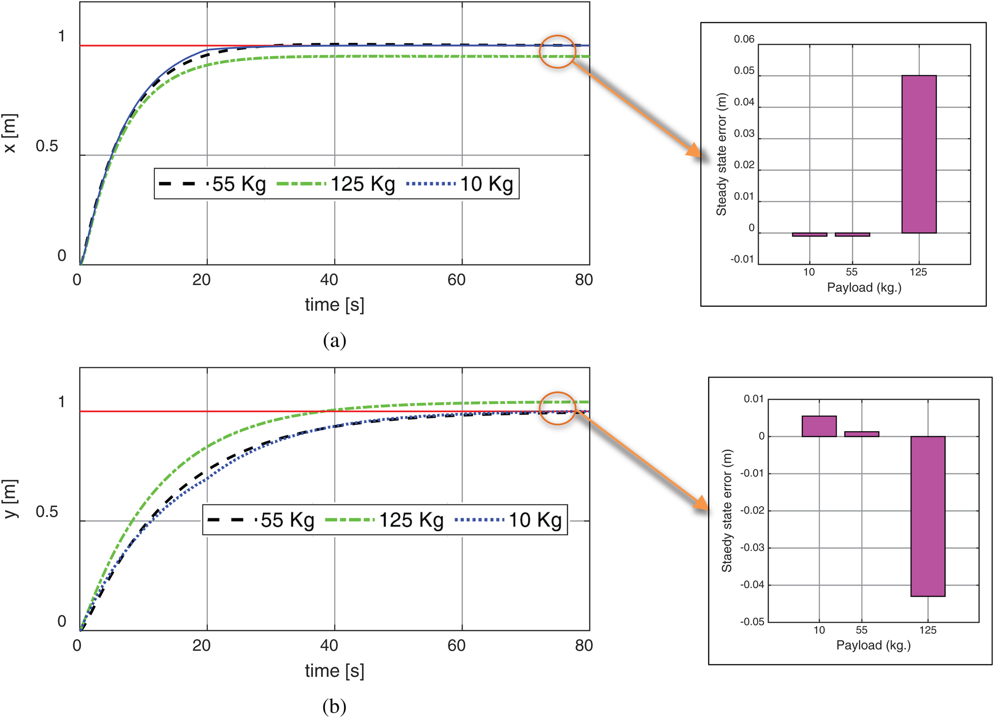
Figure 9: The system Cartesian response based on fixed point reference with different payloads: (a) X-axis; (b) Y axis
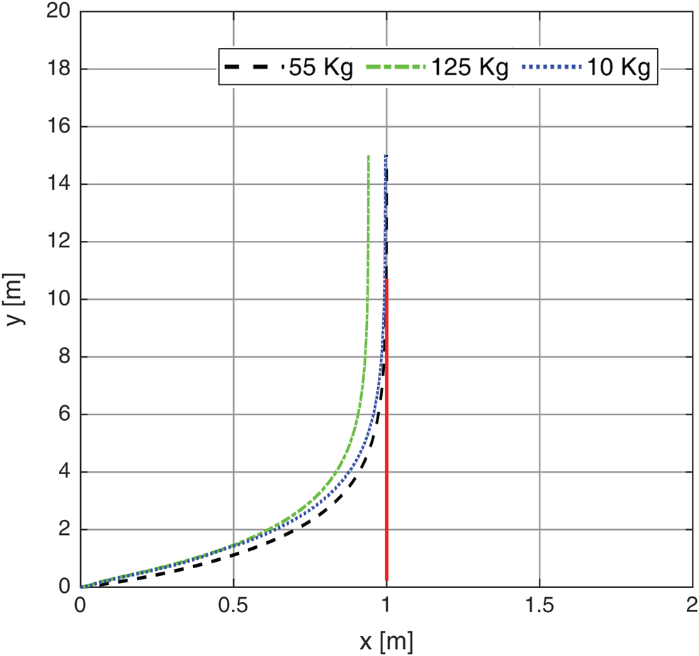
Figure 11: The system response based on fixed line path with different payloads
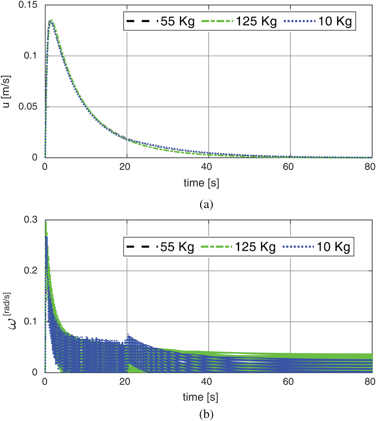
Figure 10: The system velocities based on fixed point reference with different payloads: (a) Linear velocity; (b) Rotary velocity
Figs. 11, 12 shows another test with path reference as line input (x = 1) of the wheel chair system based on PSO-P controller. The path tracking is closer to the input command with about zero for 10 kg, 0.01 m for 55 kg and 0.072 m for 125 kg. The corresponding X and Y axis response are obtained in Fig. 13. The velocities were illustrated in Figs. 14a, 14b for both of linear and rotary.
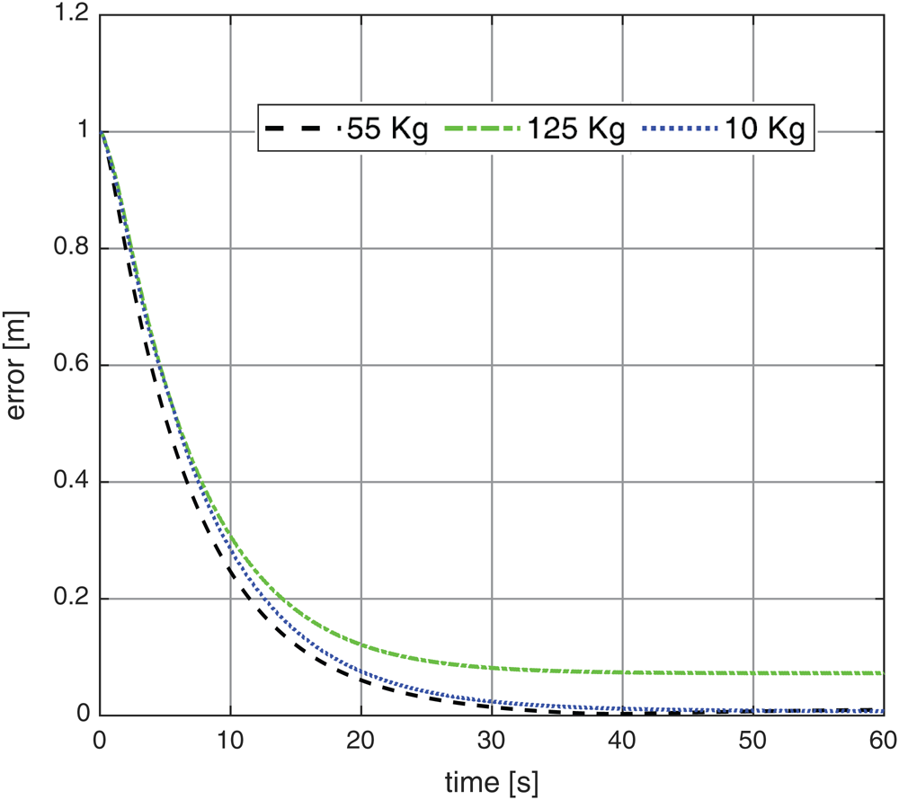
Figure 12: The system response error based on fixed line path with different payloads
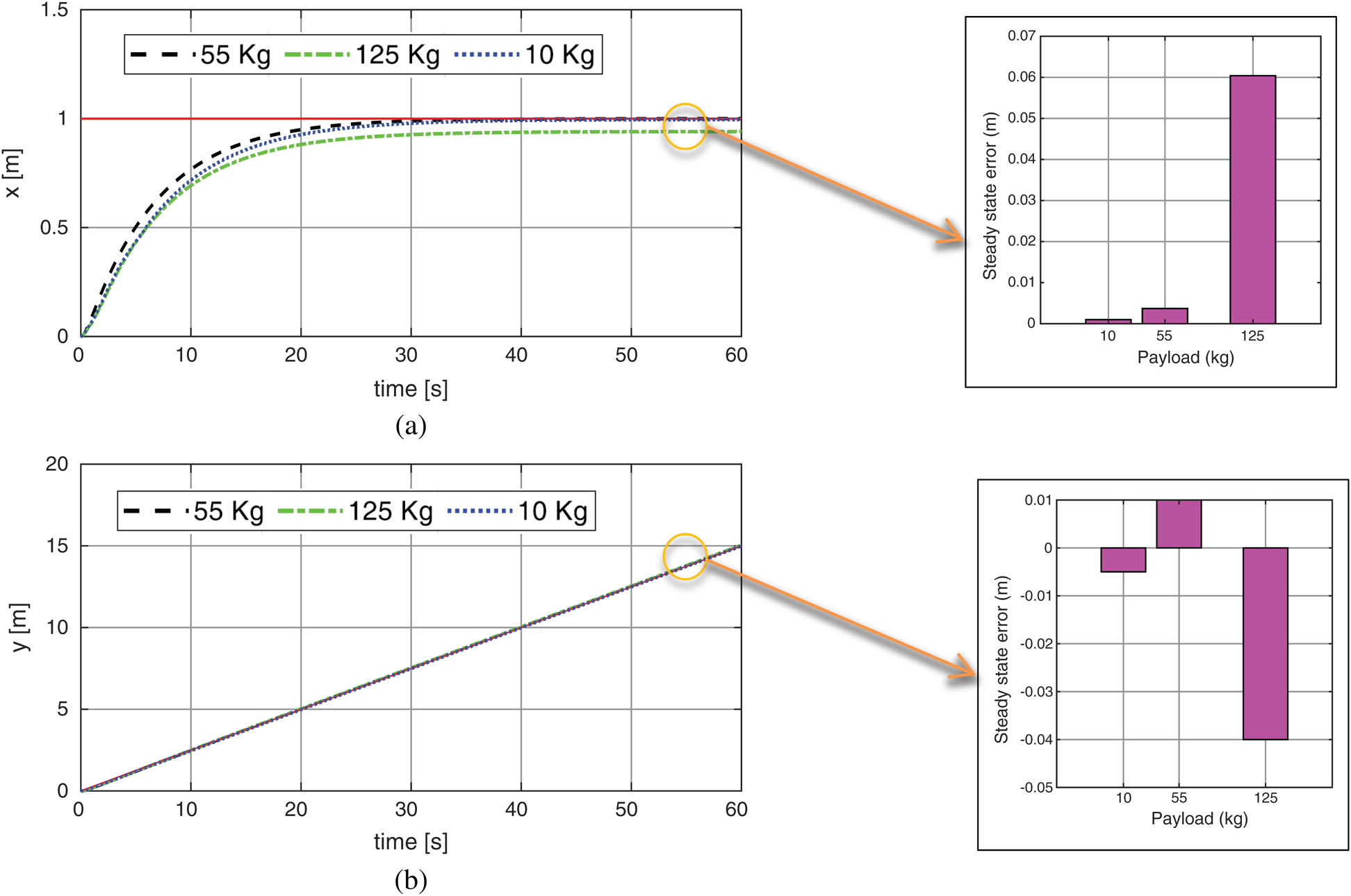
Figure 13: The system Cartesian response based on fixed line path with different payloads: (a) X-axis; (b) Y axis
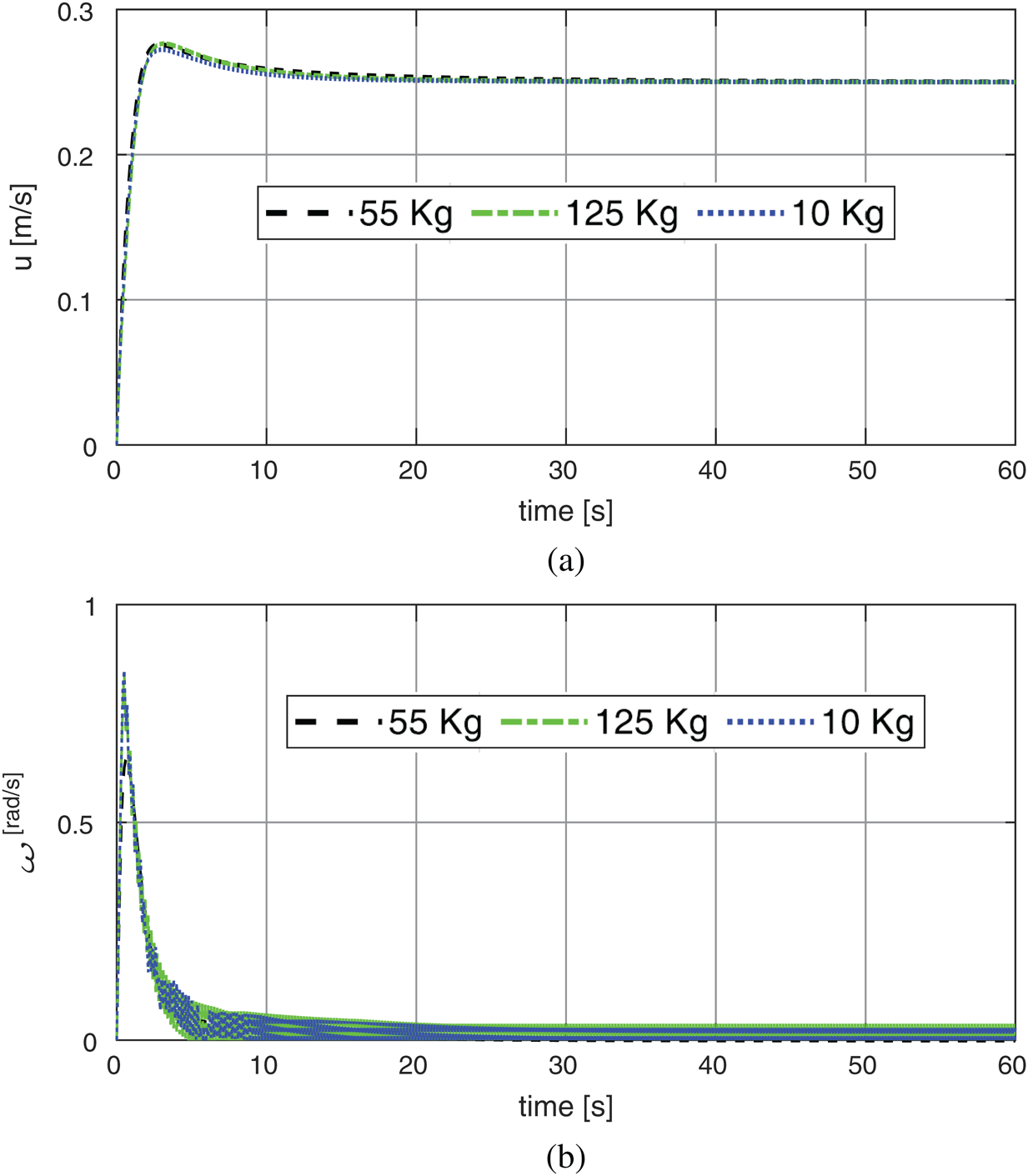
Figure 14: The system velocities based on fixed line reference with different payloads: (a) Linear velocity; (b) Rotary velocity
The circular trajectory with radius =1 m is a popular test in measuring the performance of wheel chair control System. Fig. 15 shows the circle input response applied to the PSO-P controller. The tracking response is closer to the input command. The final obtained errors are increased with increasing the dynamic load from approximately 0 to 0.075 m with 10 kg and 55 kg and finally 0.09 for 125. The results show a better performance compared with Martins et al. [22] with trajectory tracking error exhibits a steady-state value of 0.17 m for payload about 10 kg. Also the results show better circuitry shape than the work of Shojaei et al. [23]. Fig. 16 shows the system response error based on circular trajectory with different payloads. While Figs. 17a, 17b illustrates the system Cartesian response based on circular trajectory. Also by comparing the obtained results with the study of Tiep et al. [24] for 10 kg. payload we found little improvement at x-axis steady state error from 0.01136 to 0.001 and nearly similar value in y-axis (about 0.004). Finally Figs. 18a, 18b represents the system velocities based on circular trajectory with different payloads. The previous results of the simulation cleared that PSO strategy can be implemented to adjust control parameters to minimize the system trajectory error successfully. A restriction of the proposed tuning technique is that it depends on the information on the robot dynamic model. In this way, the quality of the tuning results relies upon the nature of the robot model.
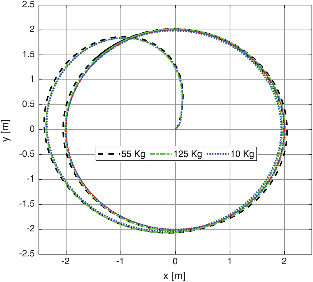
Figure 15: The system response based on circular trajectory with different payloads
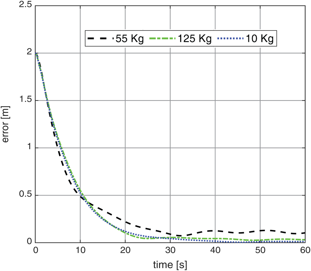
Figure 16: The system response error based on circular trajectory with different payloads
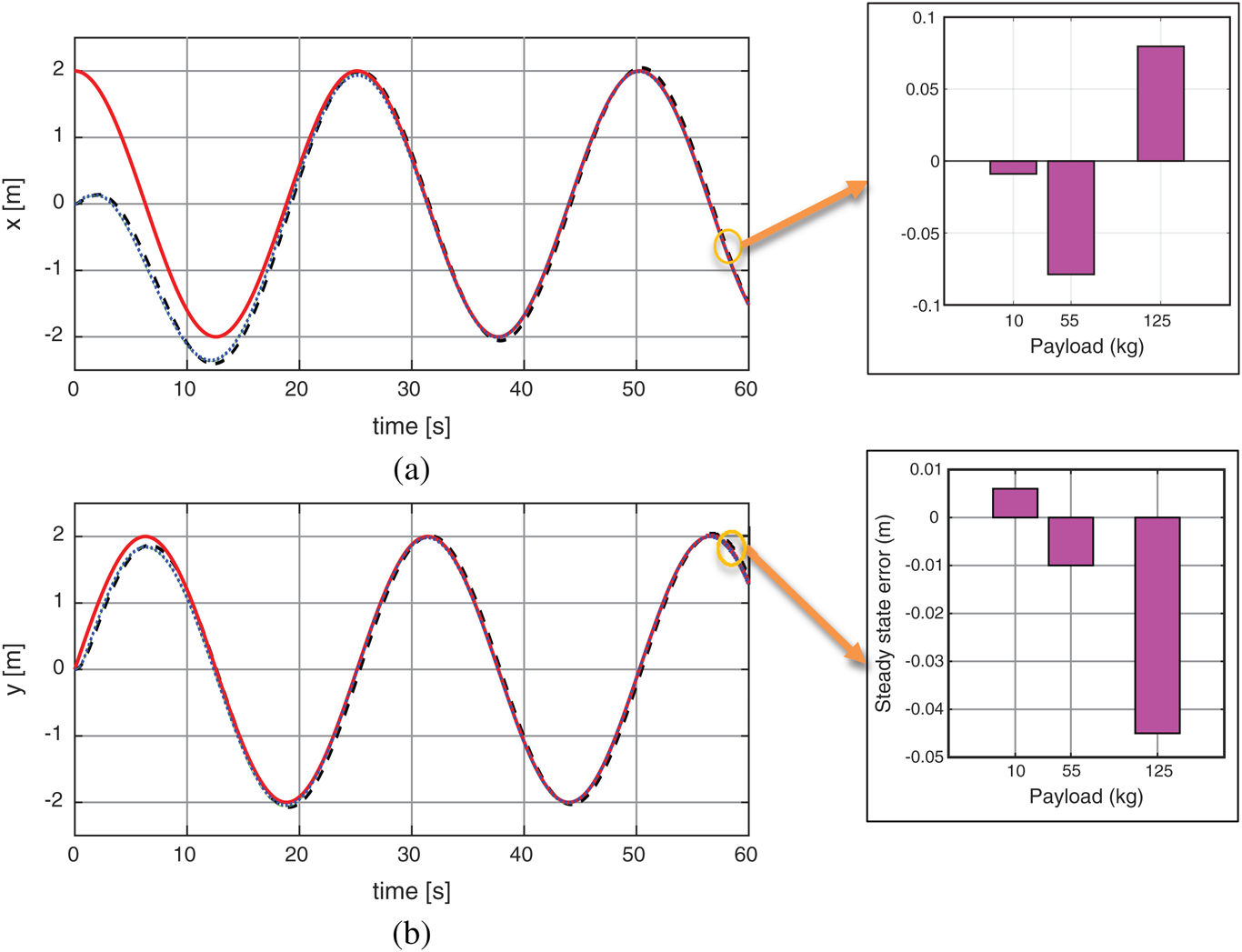
Figure 17: The system Cartesian response based on circular trajectory: (a) X-axis; (b) Y axis
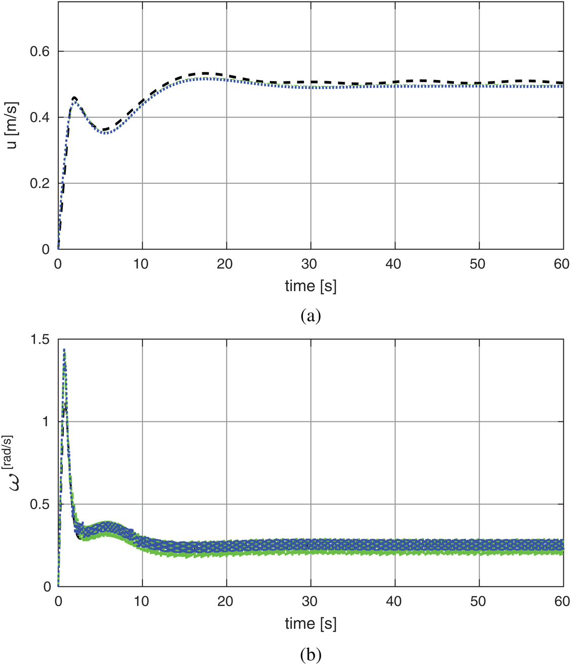
Figure 18: The system velocities based on circular trajectory with different payloads: (a) Linear velocity; (b) Rotary velocity
This article presented a tuning method based on the PSO algorithm for tune classical proportional control to track the given wheel chair reference motion. The gain concerning the proportional control was adjusted utilizing PSO methodology. In order to evaluate effects dynamic load variations, three different payloads were employed with the same PSO-P control gain. The presence of steady state error is found with different trajectories references. Therefore, the PSO-P controller can accomplish good accuracy with 10 kg and 55 kg loads. It is assured that the PSO-P control has effective performance in control of wheel chair system and provides a better performance compared with the previous similar work. Besides, application of the proportional control adjusting with PSO is a lot simpler than the customary strategies in light of the fact that there is need neither derivative calculations nor complex mathematical computations.
It has the advantages of rapid respond, tracking accuracy and good anti-interference, so the PSO-P controller is the appropriate choice for path tracking control of mobile robots with differential drive
The future work for this study is verifying experimentally the proposed control algorithm to assure its performance with non-predicted dynamic parameters.
Funding Statement: The authors would like to thank the Deanship of Scientific Research at King Abdul-Aziz University for the grant received for this research. This research was supported by King Abdul-Aziz University with research grant C: 8-135-1440, G. Mousa, and A. Almaddah, https://dsr.kau.edu.sa/Default-305-EN.
Conflicts of Interest: The authors declare that they have no conflicts of interest.
1. General Authority of Statistics. (2020). Saudi Arabia, https://www.stats.gov.sa/en. [Google Scholar]
2. H. Emam, Y. Hamam, E. Monacelli and I. Mougharbel. (2007). “Dynanic model of an electrical wheelchair with slipping detection,” in Proc. of EUROSIM, Ljubljana, Slovenia, pp. 198–204. [Google Scholar]
3. M. Gerven. (2006). “Modeling and control of an electrically driven wheelchair.” M.S. Report, University of Twente, Netherlands. [Google Scholar]
4. A. Nayyar, V. Puri, N. Nguyen and N. Le. (2018). “Smart surveillance robot for real-time monitoring and control system in environment and industrial applications,” in Proc. of Information Systems Design and Intelligent Applications, Singapore: Springer, pp. 229–243. [Google Scholar]
5. S. O. Onyango, Y. Hamam, M. Dabo, K. Djouani and G. Qi. (2009). “Dynamic control of an electrical wheelchair on an incline,” in Proc. of IEEE AFRICON’09, Nairobi, Kenya, pp. 1–6. [Google Scholar]
6. R. Kirby, S. Atkinson and E. MacKay. (1989). “Static and dynamic forward stability of occupied wheelchairs: Influence of elevated footrests and forward stabilizers,” Archives of Physical Medicine & Rehabilitation, vol. 70, no. 9, pp. 681–686. [Google Scholar]
7. R. Kirby, A. McLean and B. Eastwood. (1992). “Influence of caster diameter on the static and dynamic forward stability of occupied wheelchairs,” Archives of Physical Medicine & Rehabilitation, vol. 73, no. 1, pp. 73–77. [Google Scholar]
8. K. E. Brown, R. M. Inigo and B. W. Johnson. (1990). “Design, implementation, and testing of an adaptable optimal controller for an electric wheelchair,” IEEE Transaction on Industry Applications, vol. 26, no. 6, pp. 1144–1157. [Google Scholar]
9. H. Shu and Y. Pi. (2005). “Decoupled temperature control system based on PID neural network,” in Proc. of 5th Int. Conf. on ACSE, Cairo, Egypt, pp. 124–132. [Google Scholar]
10. D. Le. (2017). “A new ant algorithm for optimal service selection with end-to-end QoS constraints,” Journal of Internet Technology, vol. 18, no. 5, pp. 1017–1030. [Google Scholar]
11. J. Kennedy and R. Eberhart. (1995). “Particle swarm optimization,” in Proc. of the IEEE Int. Conf. on Neural Networks, Perth, WA, Australia, vol. 4, pp. 1942–1948. [Google Scholar]
12. R. Eberhart and J. Kennedy. (1995). “A new optimizer using particle swarm theory,” in Proc. 6th Int. Sym. on Micro Machine and Human Science, Nagoya, Japan, pp. 39–43. [Google Scholar]
13. X. D. Cai and Z. Y. Xu. (2006). “Weighted next reaction method and parameter selection for efficient simulation of rare events in biochemical reaction systems,” Journal of Chemical Physics, vol. 124, no. 5, pp. 44–59. [Google Scholar]
14. V. Mukherjee and S. P. Ghoshal. (2007). “Comparison of intelligent fuzzy based AGC coordinated PID controlled and PSS controlled AVR system,” International Journal of Electrical, Power & Energy Systems, vol. 29, no. 9, pp. 679–689. [Google Scholar]
15. A. A. Aly. (2011). “PID parameters optimization using genetic algorithm technique for electrohydraulic servo control system,” Intelligent Control and Automation, vol. 2, no. 2, pp. 69–76. [Google Scholar]
16. O. Hassanein and A. Aly. (2004). “Genetic-PID control for a fire tube boiler,” in Proc. of the 2nd IEEE Int. Conf. on Computational Cybernetics ICCC, Vienna, pp. 19–24. [Google Scholar]
17. A. Aly and S. Elnaggar. (2011). “Genetic PD control of a three-link rigid spatial manipulator,” International Journal on Automatic Control System Engineering, vol. 11, no. 1, pp. 15–22. [Google Scholar]
18. F. Martins, C. Celeste, R. Carelli, M. Sarcinelli and F. Bastos. (2007). “Kinematic and adaptive dynamic trajectory tracking controller for mobile robots,” in Proc. 3rd Int. Conf. on Advances in Vehicle Control and Safety AVCS’07, Buenos Aires, Argentina, pp. 1354–1363. [Google Scholar]
19. Eberhart and Y. Shi. (2001). “Particle swarm optimization: Developments, applications and resources,” in Proc. Congress on Evolutionary Computation, Seoul, South Korea, pp. 81–86. [Google Scholar]
20. R. C. Simpson. (2005). “Smart wheelchairs: A literature review,” Rehabilitation Research & Development, vol. 42, no. 4, pp. 423–438. [Google Scholar]
21. K. Pathak, J. Franch and K. Agrawal. (2005). “Velocity and position control of a wheeled inverted pendulum by partial feedback linearization,” IEEE Transactions on Robotics, vol. 21, no. 3, pp. 505–513. [Google Scholar]
22. F. N. Martins, W. C. Celeste, R. Carelli, M. Sarcinelli-Filho and T. F. Bastos-Filho. (2008). “An adaptive dynamic controller for autonomous mobile robot trajectory tracking,” Control Engineering Practice, vol. 16, no. 1, pp. 1354–1363. [Google Scholar]
23. K. Shojaei, A. M. Shahri, A. Tarakameh and B. Tabibian. (2011). “Adaptive trajectory tracking control of a differential drive wheeled mobile robot,” Robotica, vol. 29, no. 1, pp. 391–402. [Google Scholar]
24. D. K. Tiep, K. Lee, D. Y. Im, B. Kwak and Y. J. Ryoo. (2018). “Design of fuzzy-PID controller for path tracking of mobile robot with differential drive,” International Journal of FUZZY LOGIC and Intelligent Systems, vol. 18, no. 3, pp. 220–228. [Google Scholar]
 | This work is licensed under a Creative Commons Attribution 4.0 International License, which permits unrestricted use, distribution, and reproduction in any medium, provided the original work is properly cited. |