DOI:10.32604/cmc.2020.012430
| Computers, Materials & Continua DOI:10.32604/cmc.2020.012430 | |
| Article |
Comparative Thermal Performance in SiO2–H2O and (MoS2–SiO2)–H2O Over a Curved Stretching Semi-Infinite Region: A Numerical Investigation
1Department of Mathematics and Statistics, Hazara University, Mansehra, 21120, Pakistan
2Faculty of Mathematics and Statistics, Ton Duc Thang University, Ho Chi Minh City, 72915, Vietnam
3Department of Mathematics, Cankaya University, Ankara, Turkey
4Institute of Space Sciences, Magurele, 077125, Romania
5Department of Medical Research, China Medical University Hospital, China Medical University, Taichung, Taiwan
6Department of Mathematics, College of Arts and Sciences, Wadi Aldawaser, 11991, Prince Sattam Bin Abdulaziz University, Al Kharj, Saudi Arabia
*Corresponding Author: Ilyas Khan. Email: ilyaskhan@tdtu.edu.vn
Received: 30 June 2020; Accepted: 16 September 2020
Abstract: The investigation of Thermal performance in nanofluids and hybrid nanofluids over a curved stretching infinite region strengthens its roots in engineering and industry. Therefore, the comparative thermal analysis in SiO2–H2O and (MoS2–SiO2)–H2O is conducted over curved stretching surface. The model is reduced in the dimensional version via similarity transformation and then treated numerically. The velocity and thermal behavior for both the fluids is decorated against the preeminent parameters. From the analysis, it is examined that the motion of under consideration fluids declines against Fr and  . The thermal performance enhances for higher volumetric fraction and
  . Further, it is noticed that thermal performance prevailed in (MoS2–SiO2)–H2O throughout the analysis. Therefore, (MoS2–SiO2)–H2O is better for industrial and engineering uses where high heat transfer is required to accomplished different processes of production.
Keywords: Thermal performance; curved surface; SiO2–H2O and (MoS2–SiO2)–H2O; shear stresses; Nusselt number; numerical scheme
Carbon nanotubes illustrate the minimally complicated existence of graphene surface structures climbed in barrel form and atomic contour. CNTs demonstrate remarkable chemical, electrical, wet, engineered, and mechanical properties due to their combination of the small-scale, tubular structure, and large surface area. Based on the volume of graphene atoms, the carbon nanotubes are subdividing into single walled (SWCNT) and multi-walled carbon nanotubes (MWCNT). More essential efforts in this area can be made through attempts [1–8] and various studies. Convective fluid flow and heat transfer are used for nuclear reactors owing to permeable space in geology applications, cleaning and liquid plastic molding, microbial, and combustion.
Darcy has developed an essential semi-experimental groundbreaking equation for low porosity and low-velocity flux. By increasing Reynolds number, nonlinearity occurs from the expansion of inertial force in the semi-observational equation. In particular, the Darcy–Forchheimer flow model used and predicted a modified meaning in the energy equation by using the nonlinear concept of velocity. The Darcy–Forchheimer hybrid convection with thermophoresis and viscous dissipation in a liquid vacuum filled with air. This way, tests and numerous investigations [9–15] tracked the development of new attempts on the Darcy–Forchheimer model. Besides, some nanofluid-related studies can be found in [16–17]. Esfe et al. [18] explored the use of COOH−functionalized carbon nanotubes and nanofluid based on ethylene glycol-water in the heating and cooling system for heat transfer efficiency.
Experimental and computational experiments are still ongoing surrounding the hybrid nanofluids. Dardan et al. [19] presented the analysis of hybrid nanofluids. Esfe et al. [20] analyzed, the hybridization of carbon nanotubes with silicon oxide and silver nanoparticles in the presence of plasma. Sarkar et al. [21] characterized the nanofluid by aluminum containing the Copper water base. In the presence of hybrid nanoparticles, they addressed the thermo-physical action of the material and concluded about the attitude of efficacy in that thermal conduction. Nanofluids are a nowadays popular area of research. The concept of nanofluids was introduced by Choi’s [22]. In the existence of CuO nanoparticles throughout the water and Al2O3 particles in ethylene glycol and soil, Suresh et al. [23] performed experimental heat transfer experiments.
We also observed that heat transfer experimentally through the use of individual particles improves the one-fifth time. Nine et al. [24] and Toghraie et al. [25] experimented with the help of copper oxide found that the thermal conductivity was improved. Khan et al. [26] addressed the transportation of a nanofluid to a stretched surface at the boundary layer. They concluded that there are opposing effects for Prandtl number, Lewis number, Brownian motion parameter, and thermophoresis parameter, Nusselt number and Sherwood number, respectively. Using the applications in the electrically conductive fluid and magnetic field will monitor the cooling rate and the desired end product properties.The use of the magnetic field was used to purify non-metallic inclusions of the molten metals. Two examples of this type of effect are fusing metals into an electric furnace by applying a magnetic field and cooling the first wall within a nuclear reactor containment vessel where the hot plasma is separating from the ground by using a magnetic field. Considering thermal radiation, Sheikholeslami et al. [27] performed a statistical study of Al2O3 water-based nanofluid free convection with MHD. The properties of Cu-water nanofluid stagnation point flow and heat transfer over a horizontal pipe that extends/ shrinks were studied by Sulochana et al. [28].
This work aims at investigating the heat transfer change due to the existence of hybrid nanofluid flow over a curved stretching sheet. The suspension of two different nanoparticles known as sand called (MoS2) and (SiO2) is defined as a hybrid nanofluid. Water is actually used as the base fluid. This is evaluated for heat transfer and thermal stability, with the introduction of MoS2/SiO2 nanoparticles as the base fluid of liquids. Curvilinear coordinates perform a mathematical approximation of the physical flow problem and numerically solved nonlinear coupled differential equations using shooting algorithms after simplification. The effect of new essential parameters on the velocity and temperature distributions are discussed using graphs. The skin friction coefficient and the Nusselt number are tabulated for different values of the basic parameters.
2 Statement Geometry and Nanofluid Models Formulation
We consider the steady two-dimensional, incompressible flow of the nanofluid coiled into R-circle radius over a stretching sheet. By preserving steady roots, the sheet is stretched through the forces exerted along the s-direction, and the direction of r is perpendicular to it. The stretching velocity of the surface is u = as, where a is constant (a > 0). The surface temperature is held stable at Tw(s) = A(s/l), where Tw > T∞ is a constant with T being the atmospheric uniform temperature of the fluid. The empirical flow explanation of the present problem in engineering is shown in Fig. 1
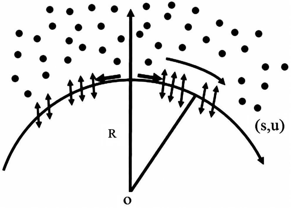
Figure 1: Physical model of the problem
Under these conditions together with the approximations of boundary layers, the governing equations are;


subject to boundary conditions


where Eq. (1) preserves the mass, transverse and axial components expressed in Eqs. (2) and (3) respectively. Through the given energy equation Eq. (4), the heat transfer shall be investigated as well. However, u and v denote the components of velocity in s and r directions respectively, p is pressure, R denotes radius of curvature,  is hybrid nanofluid density, u and v denote the velocity components in s and r direction, p is pressure, K* is porous permeability of space, and Cb is the drag coefficient. F = Cb/(LK)*1/2 is the non-uniform coefficient of inertia, while Tw and T∞ are the wall and ambient temperatures respectively.
We implement the following a similarity transformation to further promote this process;


2.2 Effective Nanofluid Models
The following nanofluid models are used to improve the thermal performance


2.3 Effective Hybrid Nanofluid Models
The following hybrid nanofluid models are implemented to improve the thermal performance in the hybrid nanofluid


Where 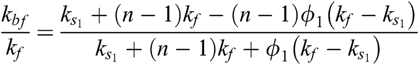
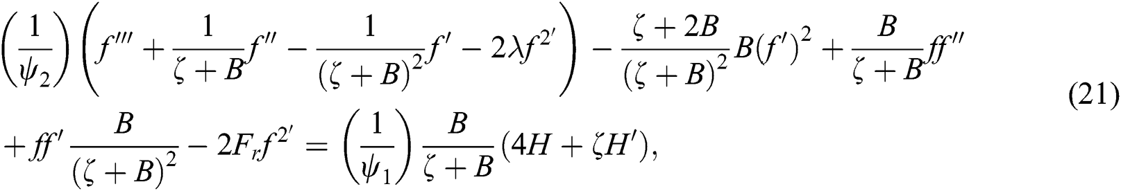
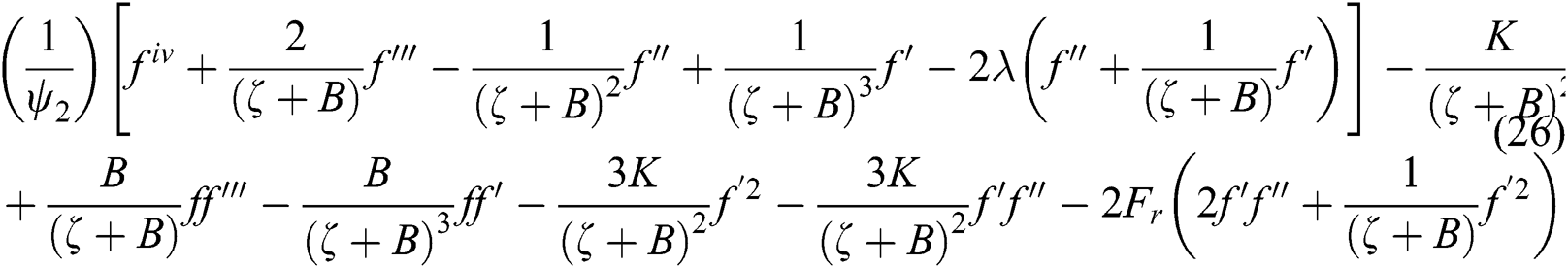
Surely, Eq. (1) automatically validates and (2)–(4) transforms the ordinary differential equation into non-dimensional equation as follows;


where


Once we obtain fluid velocity pressure, then H can be determined from Eqs. (20) and (21) and can be written as
The transformed boundary conditions are;


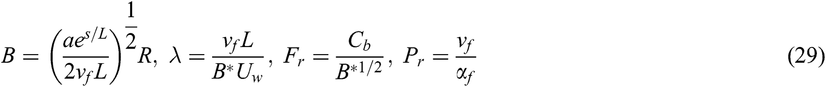
In the relationships above, Pr represents the Prandtl number, Fr is the Forchheimer number, λ is the local porosity parameter, and the curvature parameter is B. These are defined by the following formulas:
2.4 Quantity for Thermal Performance
The physical quantities of interest are skin friction coefficient Cf and local Nusselt number  , which are defined as


Where  and
and  along the s-direction are defined as

The skin fraction coefficient and the local number Nusselt shall be


where 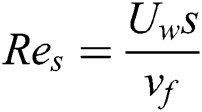 elucidates local Reynolds number.
This section dedicates to the graphical analysis of the effect on the velocity and temperature distributions of several critical emerging parameters. Nanofluid based diagrams are shows using SiO2 and MoS2–SiO2 water-based hybrid nanofluid. The comparative study of nanofluids and hybrid nanofluids is giving special consideration. Static lines show the results for nanofluid and pointed lines in the following diagrams show the results for hybrid nanofluid. Figs. 2–14 are shown for velocity and temperature distributions for specific Forchheimer number Fr values, curvature parameter B, local porosity parameter λ, hybrid volumetric fractions ∅2, of nanofluid, and temperature exponent A respectively.
3.1 The Velocity Against Preeminent Parameters
Fig. 2 shows to investigate the effect on the velocity of Forchheimer number Fr. It is a note from Fig. 2 that Forchheimer number Fr plays a part in increasing velocity. It is because the surface’s expansion causes the fluid movement, and therefore, any fluid flow shifts on the expanding surface will decelerate the flow.
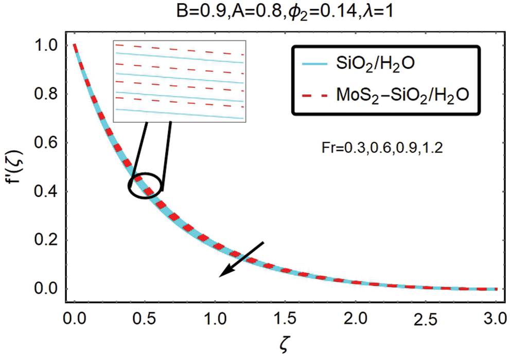
Figure 2: The variations of velocity for varying Fr
Fig. 3 indicates the opposite trend for the increased velocity. From this figure, it shows that velocity decreases as curvature parameter B increases. However, it is apparent from this calculation that for hybrid nanofluid, the change in velocity is substantially more significant.
Figure 3: The variations of velocity for varying B
For the velocity profile, the effect of the local porosity parameter λ is demonstrated by Fig. 4, the fluid flow is shown to intensify, and as the curvature parameter increases. At the same time, the thickness of the boundary layer decreases. Physically, this means that the bent surface bendiness helps to speed up fluid flow over it. For hybrid nanofluid, this speed increase is marginally more significant.
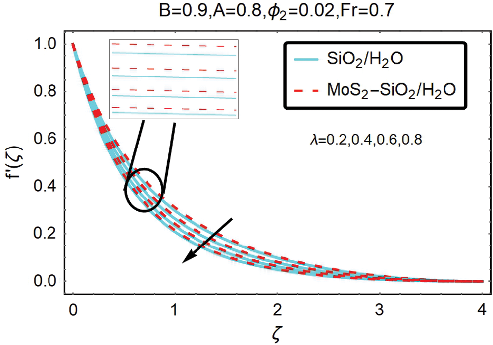
Figure 4: The variations of velocity for varying λ
Fig. 5 shows to analyze the velocity influence of the volumetric fraction ∅2 for hybrid nanofluid. From this figure, it is discovering that for large volumetric fraction ∅2 of MoS2–SiO2, hybrid nanofluid flows faster than nanofluid.
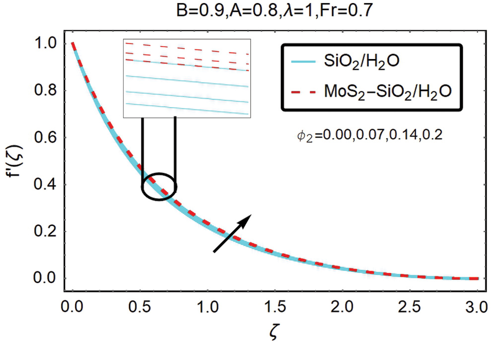
Figure 5: The variations of velocity for varying ∅2
3.2 The Temperature Against Preeminent Parameters
The effect on the temperature profile of similar emergent parameters shows in Figs. 6 to 10. Graphs are demonstrating for better representation of nano and hybrid nanofluids. Additionally, each figure illustrates five distinct forms of variables. Solid and pointed lines show the efficiency of nano and hybrid nanofluids, respectively. Pointed and solid lines also reflect increasing parameters including temperature exponent A for non-zero values, curvature parameter B, Forchheimer number Fr, hybrid nanofluid volumetric fractions ∅2, and local porosity parameter, respectively.
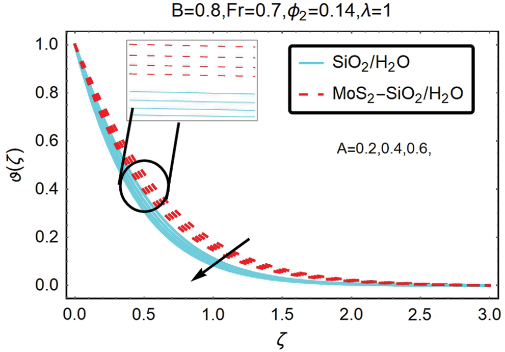
Figure 6: The variations of temperature for varying A
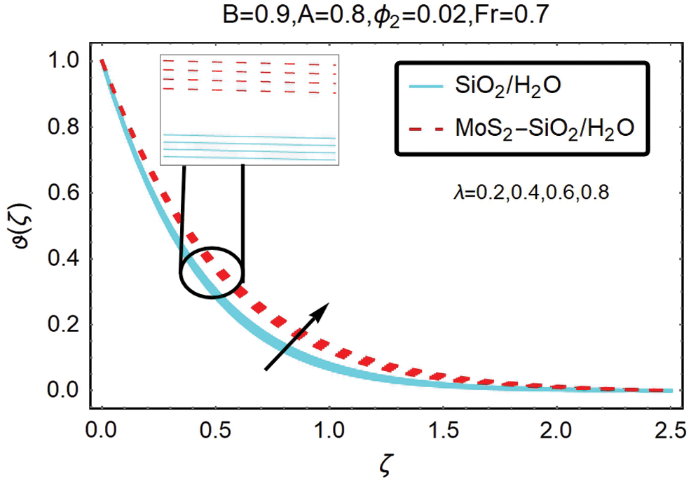
Figure 10: The variations of temperature for varying 
Fig. 6 diagrammed to study the temperature influence of temperature exponent A. It is revealed from this figure that temperature increases when temperature exponent  decreasing. It is because the value increase in A enhances the results of the conduction and thus raises the temperature. This increase is widespread away from the surface in the field and adds to the air heat flux. Nanoparticles with a hybrid nanofluid shaped blade have the maximum temperature. In comparison, these results are more reliable than nanofluid in the case of hybrid nanofluid, since hybrid nanofluid has more thermal conductivity than nanofluid.
Fig. 7 shows the influence of curvature parameter B on nano and hybrid nanofluid temperature, reducing the thickness of the surface and the thermal limit layer with curvature B increasing. That is because the curvature parameter contributes to the fluid flow deceleration and consequently contributes to the extent of the rising temperature. From this observation, it is also apparent that the temperature magnitude for hybrid nanofluid is higher for nanofluid for that values of B.
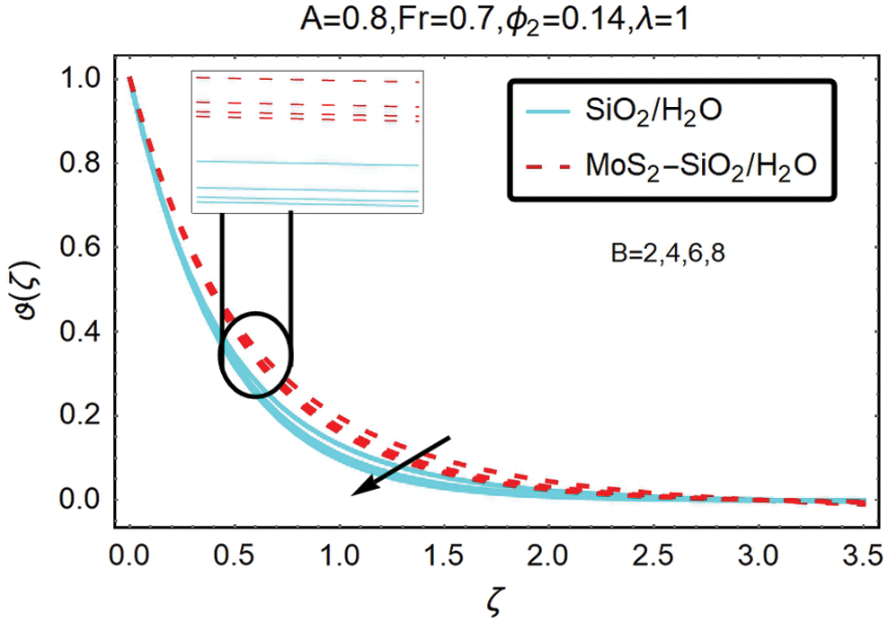
Figure 7: The variations of temperature for varying B
The temperature operation for Forchheimer number Fr shows in Fig. 8. The temperature increases by Forchheimer number Fr.
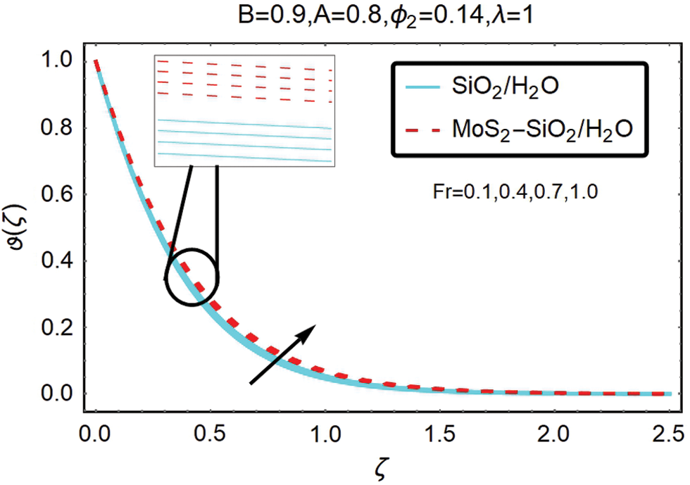
Figure 8: The variations of temperature for varying Fr
Fig. 9 plotted to analyze the influence on the temperature of the volumetric fraction ∅2 of hybrid nanofluid. This figure shows that for sizeable volumetric fraction ∅2, hybrid nanofluid flows more rapidly than nanofluid.
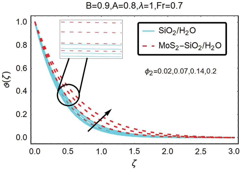
Figure 9: The variations of temperature for varying ∅2
Fig. 10 indicates the results of the local porosity parameter λ. From this Figure, it inferred that the parameter of local porosity affects the distribution of temperature by increasing it. It is because the atmosphere temperature is greater than that place far from the earth, and more heat is transferred from the ground into the air which adds to the thickness of the maximum thermal layer. This increase in temperature is also assumed to be influential in the case of hybrid nanofluid.
Figs. 11 and 12 drawn to study the Nusselt number influence of the local porosity parameter λ, volumetric fraction ∅2 of the nanoparticles, and the Forchheimer number Fr. The tests for hybrid nanofluid shows in Fig. 11. This equation elucidates that the Nusselt number decreases with an increase in the Forchheimer number Fr and volumetric fractions ∅2 of nanoparticles (MoS2–SiO2).
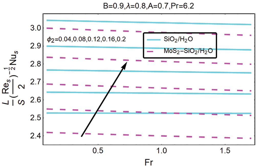
Figure 11: The variation of  for varying ∅2 and Fr
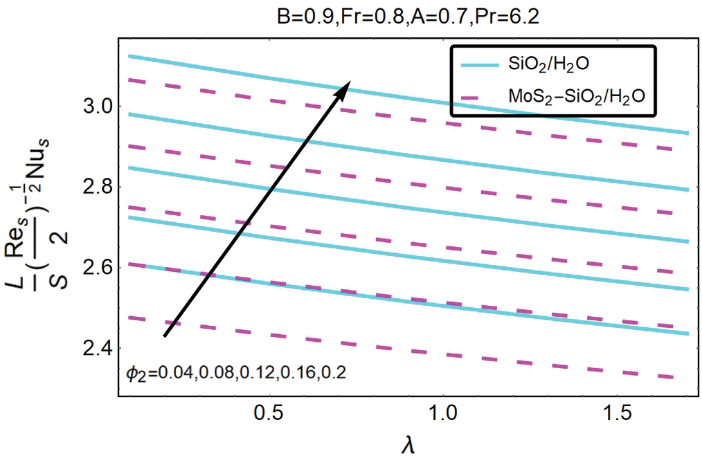
Figure 12: The variation of  for varying ∅2 and λ
From Fig. 12 shows that the amount of the local heat transfer decreases with an increase in volumetric fractions ∅2 of local porosity parameters λ and nanoparticles. Comparison of Figs. 11 and 12 showed that Nusselt number magnitude is greater for (MoS2–SiO2) than (SiO2).
Figs. 13 and 14 show the variation for the effect of these changing parameters on the skin friction coefficient for nanofluid and hybrid nanofluid, respectively. Discussion of these figures reveals that the local porosity λ feature, the volumetric fraction ∅2 of nanoparticles, and the Forchheimer number Fr contribute to a decrease in the skin friction coefficient's magnitude, decreasing the significance of the skin friction coefficient for nano and hybrid nanofluids. By contrast, in the case of nanofluid, the importance of the coefficient of skin friction is marginally higher than the hybrid nanofluid.
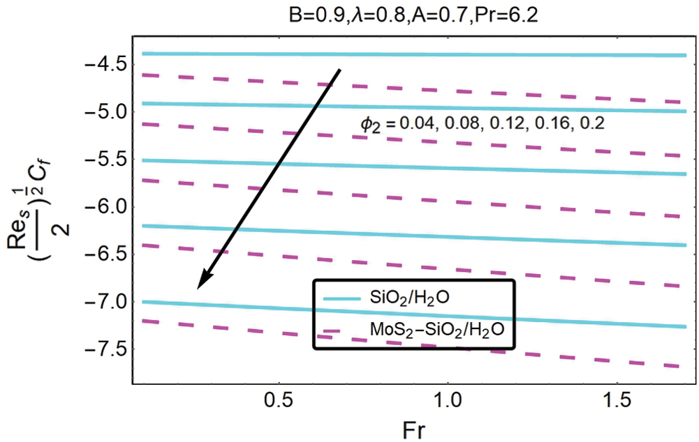
Figure 13: The variation of  for varying ∅2 and Fr
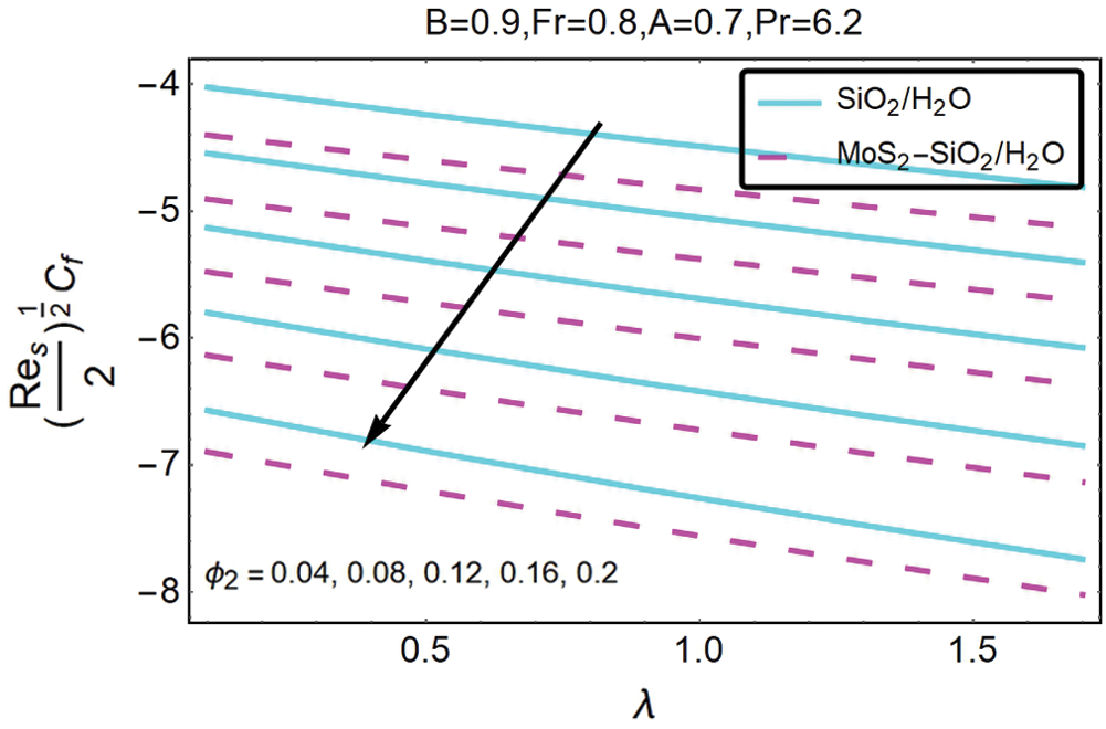
Figure 14: The variation of  for varying ∅2 and λ
And from Fig. 14, it is inferred that the skin friction coefficient decreases with an increase in volumetric fractions ∅2 of local porosity parameters λ and nano particles. The comparison of Figs. 13 and 14 showed that the magnitude of the skin friction coefficient is marginally higher than that of hybrid nanofluid.
The comparative study of the nanofluid and hybrid nanofluid is conducting over a curved stretching surface. The numerical analysis of the physical problem was work out in curvilinear coordinates. For specific parameter values ∅2, λ, B, A, and Fr, the governing Eqs. (9) and (10) with similar boundary conditions (11) are numerically treated. We used Mathematica package ND Solver. Detailed numerical calculations aimed at giving the flow problem a physical imagination for different estimations of the parameters displaying the flow qualities. The results for  and Nu are graphically representing. Below are the interesting concluding highlights from this article.
•It should remember that during the increase of the SiO2 and MoS2–SiO2 fraction of nanoparticle thickness, the thermal boundary layer, and the velocity boundary layer increase.
• increases, and
  decreases with rising values of Fr.
•As far as the first solution is concerned, we found that  magnifies for higher λ values while
  responds to the contrary.
•Both fields of velocity and temperature demonstrate opposite correlations for more significant percentages of reliable nanoparticulate content  .
.
•A different activity is observed in the fields of velocity and temperature when the parameter of local porosity π is rising.
Funding Statement: The author(s) received no specific funding for this study.
Conflicts of Interest:The authors declare that they have no conflicts of interest to report regarding the present study.
References
1J. Wang, J. Zhu, X. Zhang and Y. Chen. (2013), “Heat transfer and pressure drop of nanofluids containing carbon nanotubes in laminar flows. ,” Experimental Thermal and Fluid Sciences, vol. 44, pp, 716–721, .
2M. R. Safaei, H. Togun, K. Vafai, S. N. Kazi and A. Badarudin. (2014), “Investigation of heat transfer enhancement in a forward-facing contracting channel using FMWCNT nanofluids. ,” Numerical Heat Transfer, Part A: Application, vol. 66, no. (12), pp, 1321–1340, .
3R. Ellahi, M. Hassan and A. Zeeshan. (2015), “Study of natural convection MHD nanofluid by means of single and multi-walled carbon nanotubes suspended in a salt-water solution. ,” IEEE Transactions on Nanotechnology, vol. 14, no. (4), pp, 726–734, .
4T. Hayat, Z. Hussain, T. Muhammad and A. Alsaedi. (2016), “Effects of homogeneous and heterogeneous reactions in flow of nanofluids over a nonlinear stretching surface with variable surface thickness. ,” Journal of Molecular Liquids, vol. 221, pp, 1121–1127, .
5Z. Iqbal, E. Azhar and E. N. Maraj. (2017), “Transport phenomena of carbon nanotubes and bio convection nanoparticles on stagnation point flow in presence of induced magnetic field. ,” Physica E: Low-Dimensional Systems and Nanostructures, vol. 91, pp, 128–135, .
6U. Khan, N. Ahmed and S. T. Mohyud-Din. (2017), “Numerical investigation for three-dimensional squeezing flow of nanofluid in a rotating channel with lower stretching wall suspended by carbon nanotubes. ,” Applied Thermal Engineering, vol. 113, pp, 1107–1117, .
7T. Hayat, F. Haider, T. Muhammad and A. Alsaedi. (2017), “On Darcy–Forchheimer flow of carbon nanotubes due to a rotating disk. ,” International Journal of Heat and Mass Transfer, vol. 112, pp, 248–254, .
8T. Hayat, T. Muhammad, A. Alsaedi and M. S. Alhuthali. (2015), “Magnetohydrodynamics three-dimensional flow of viscoelastic nanofluid in the presence of nonlinear thermal radiation. ,” Journal of Magnetism and Magnetic Materials, vol. 385, pp, 222–229, . [Google Scholar]
9M. A. Sadiq and T. Hayat. (2016), “Darcy–Forchheimer flow of magneto Maxwell liquid bounded by convectively heated sheet. ,” Results in Physics, vol. 6, pp, 884–890, . [Google Scholar]
10S. A. Bakar, N. M. Arifin, R. Nazar, F. Ali and M. Pop. (2016), “Forced convection boundary layer stagnation-point flow in Darcy–Forchheimer porous medium past a shrinking sheet. ,” Frontiers in Heat and Mass Transfer, vol. 7, pp, 38–44, .
11T. Hayat, T. Muhammad, S. Al-Mezal and S. J. Liao. (2016), “Darcy–Forchheimer flow with variable thermal conductivity and Cattaneo–Christov heat flux. ,” International Journal of Numerical Methods for Heat and Fluid Flow, vol. 26, no. (8), pp, 2355–2369, .
12J. C. Umavathi, O. Ojjela and K. Vajravelu. (2017), “Numerical analysis of natural convective flow and heat transfer of nanofluids in a vertical rectangular duct using Darcy–Forchheimer Brinkman model. ,” International Journal of Thermal Sciences, vol. 111, pp, 511–524, .
13T. Hayat, F. Haider, T. Muhammad and A. Alsaedi. (2017), “Darcy–Forchheimer flow due to a curved stretching surface with Cattaneo–Christov double diffusion: A numerical study. ,” Results in Physics, vol. 7, pp, 2663–2670, .
14T. Hayat, A. Aziz, T. Muhammad and A. Alsaedi. (2017), “Darcy–Forchheimer three-dimensional flow of Williamson nanofluid over a convectively heated nonlinear stretching surface. ,” Communication in Theoretical Physics, vol. 68, no. (3), pp, 387–393, .
15T. Muhammad, A. Alsaedi, S. A. Shehzad and T. Hayat. (2017), “A revised model for Darcy Forchheimer flow Maxwell nanofluid subject to convective boundary condition. ,” Chinese Journal of Physics, vol. 55, no. (3), pp, 963–976, . [Google Scholar]
16A. Sajadi and M. Kazemi. (2011), “Investigation of turbulent convective heat transfer and pressure drop of TiO2/water nanofluid in circular tube. ,” International Communication in Heat and Mass Transfer, vol. 38, no. (10), pp, 1474–1478, . [Google Scholar]
17M. Soltanimehr and M. Afrand. (2016), “Thermal conductivity enhancement of COOH-functionalized MWCNTs/ethylene glycol-water nanofluid for application in heating and cooling systems. ,” Applied Thermal Engineering, vol. 105, pp, 716–723, . [Google Scholar]
18M. Esfe, M. Afrand, S. Wongwises, A. Naderi, A. Asadi. (2015). et al., “Applications of feed forward multilayer perceptron artificial neural networks and empirical correlation for prediction of thermal conductivity of Mg (OH) 2-EG using experimental data. ,” International Communications in Heat and Mass Transfer, vol. 67, pp, 46–50, . [Google Scholar]
19E. Dardan, M. Afrand and A. Isfahani. (2016), “Effect of suspending hybrid nano-additives on rheological behavior of engine oil and pumping power. ,” Applied Thermal Engineering, vol. 109, pp, 524–534, . [Google Scholar]
20M. Esfe, S. Saedodin, W. Yan, M. Afrand and N. Sina. (2016), “Study on thermal conductivity of water-based nanofluids with hybrid suspensions of CNTs/Al2O3 nanoparticle. ,” Journal of Thermal Analysis and Calorimetry, vol. 124, no. (1), pp, 455–460, . [Google Scholar]
21J. Sarkar, P. Ghosh and A. Adil. (2015), “A review on hybrid nanofluids: Recent research, development and applications. ,” Renewable and Sustainable Energy Reviews, vol. 43, pp, 164–177, . [Google Scholar]
22S. Choi and S. Kalaiselvam. (2014), “Experimental analysis of hybrid nanofluid as a coolant. ,” Procedia Engineering, vol. 97, pp, 1667–1675, . [Google Scholar]
23S. Suresh, K. Venkitaraj, P. Selvakumar and M. Chandrasekar. (2011), “Synthesis of Al2O3-Cu/water hybrid nanofluids using two step method and its thermo-physical properties. ,” Colloids and Surfaces A: Physicochemical and Engineering Aspects, vol. 388, no. (1–3), pp, 41–48, . [Google Scholar]
24M. Nine, B. Munkhbayar, M. Rahman, H. Chung and H. Jeong. (2013), “Highly productive synthesis process of well dispersed Cu2O and Cu/Cu2O nanoparticles and its thermal characterization. ,” Materials Chemistry and Physics, vol. 141, no. (2–3), pp, 636–642, . [Google Scholar]
25D. Toghraie, V. A. Chaharsoghi and M. Afrand. (2016), “Measurement of thermal conductive of Zno–TiO2/EG hybrid nanofluid: Effects of temperature and nanoparticles concentration. ,” Journal of Thermal Analysis and Calorimetry, vol. 125, no. (1), pp, 527–535, . [Google Scholar]
26W. A. Khan and I. Pop. (2010), “Boundary-layer flow of a nanofluid past a stretching sheet. ,” International Journal of Heat and Mass Transfer, vol. 53, no. (11–12), pp, 2477–2483, . [Google Scholar]
27M. Sheikholeslami, T. Hayat and A. Alsaedi. (2016), “MHD free convection of Al2O3-water nanofluid considering thermal radiation: A numerical study. ,” International Journal of Heat and Mass Transfer, vol. 96, pp, 513–524, . [Google Scholar]
28C. Sulochana and N. Sandeep. (2016), “Stagnation point flow and heat transfer behavior of Cu-water nanofluid towards horizontal and exponentially stretching/shrinking cylinders. ,” Applied Nanoscience, vol. 6, no. (3), pp, 451–459, . [Google Scholar]
 | This work is licensed under a Creative Commons Attribution 4.0 International License, which permits unrestricted use, distribution, and reproduction in any medium, provided the original work is properly cited. |