DOI:10.32604/cmc.2020.012267
| Computers, Materials & Continua DOI:10.32604/cmc.2020.012267 | |
| Article |
A Physical Layer Network Coding Based Tag Anti-Collision Algorithm for RFID System
1School of Information Engineering, Yancheng Institute of Technology, Yancheng, 224000, China
2School of Computer, Nanjing University of Posts and Telecommunication, Nanjing, 210003, China
3Modern Agricultural Resources Intelligent Management and Application Laboratory, Huzhou Normal University, Huzhou, 313000, China
4School of Science and Technology, Troy University, Troy, 36082, USA
*Corresponding Author: Xing Shao. Email: shaoxing269@hotmail.com
Received: 23 June 2020; Accepted: 12 August 2020
Abstract: In RFID (Radio Frequency IDentification) system, when multiple tags are in the operating range of one reader and send their information to the reader simultaneously, the signals of these tags are superimposed in the air, which results in a collision and leads to the degrading of tags identifying efficiency. To improve the multiple tags’ identifying efficiency due to collision, a physical layer network coding based binary search tree algorithm (PNBA) is proposed in this paper. PNBA pushes the conflicting signal information of multiple tags into a stack, which is discarded by the traditional anti-collision algorithm. In addition, physical layer network coding is exploited by PNBA to obtain unread tag information through the decoding operation of physical layer network coding using the conflicting information in the stack. Therefore, PNBA reduces the number of interactions between reader and tags, and improves the tags identification efficiency. Theoretical analysis and simulation results using MATLAB demonstrate that PNBA reduces the number of readings, and improve RFID identification efficiency. Especially, when the number of tags to be identified is 100, the average needed reading number of PNBA is 83% lower than the basic binary search tree algorithm, 43% lower than reverse binary search tree algorithm, and its reading efficiency reaches 0.93.
Keywords: Radio frequency identification (RFID); tag anti-collision algorithm; physical layer network coding; binary search tree algorithm
As a kind of automatic identification technology, radio frequency identification (RFID) [1] system can identify object even when the object is not in its visual range. Compared with other automatic identification technologies, RFID has the advantages of high accuracy, long reading distance, large amount of data storage, strong robustness and so on. In addition, as one of the key technologies of Internet of Things (IoT), RFID technology is widely used in warehousing logistics, goods tracking, identity recognition, access control and many other fields.
A typical RFID system [2] consists of a reader and a number of tags. Information about an object is stored in the tag, while the reader is used to read and write the information in the tag. When a plurality of tags is in the working range of a reader, and these tags use the same communication frequency to send information to the reader, the transmission signals of these tags interfere with each other. Once the signal interference is detected by a reader, the reader will not be able to read the information in the tags correctly, which is called the tag collision problem of RFID system [3–6]. Actually, the tag collision problem seriously restricts the reading and writing efficiency of RFID system. Therefore, the research on tag collision problem is one hot topic of RFID research and of great significance to the application of RFID systems.
2 Related Works and Motivation
Actually, in order to solve the tag collision problem of RFID system, some tag anti-collision algorithms have been proposed. These algorithms can be divided into two categories: ALOHA based indeterminate algorithm [5] and tree based deterministic algorithm [6].
ALOHA based algorithm controls tags access the channel to reduce the tag collision possibility. Typical ALOHA based algorithms includes slotted ALOHA algorithm [7], frame slotted algorithm [8–10], and bit slot algorithm [11], etc. In addition, the tags’ number estimation algorithm [12] is also an important improvement of ALOHA based algorithms. As a kind of random algorithm, ALOHA based algorithm cannot ensure that a tag is read in a certain period of time and some tags may not be read for a long time, which is called the problem of “tag starvation”.
In tree based algorithm, tags are divided into groups continuously when a collision occurs. When there is only one tag in a group, the tag will be read correctly without collision. And all tags using tree based algorithm will be read in this way. In the binary search tree based algorithms, once tag collision is detected, tags will be divided into 2 groups and finally, the reader will read all tags’ information without collision.
Typical tree based algorithms include tree splitting algorithm (TS) [13], query tree algorithm (QT) [14,15], binary search tree algorithm (BST) [6], dynamic binary search tree (DBST) [16], regressive binary search tree algorithm (RBST) [17,18]. As a deterministic algorithm, tree based algorithm is able to avoid the problem of “tag starvation”. Therefore, more and more attention has been paid to the research on tree based anti-collision algorithm for RFID system.
In existing tree based algorithms, the collision signal will be discarded directly when a collision is detected. However, the conflicting signal is usually the superposition of multiple tags’ information. If the collision signal in tree based algorithm could be exploited to obtain the original tag information, the performance of tree based algorithm will be further improved significantly.
In recent years, the emergence of network coding technology [19,20] provides an opportunity to exploit collision information of multiple tags to improve the efficiency of the tree based algorithm.
Network coding [19] allows the intermediate nodes in the network to encode the received data. Using network coding, the multicast transmission rate can reach the theoretical upper limit value according to the maximum flow minimum cut theory.
Network coding can be applied to physical layer, which is called physical network coding [21] and exploits the additive nature of simultaneously arriving electromagnetic waves for equivalent coding operation. Exactly, the conflicting signal of multiple tags in RFID system is the superposition signal of multiple tags. Therefore, the conflicting signal can be treated as a kind of physical network coding, and the original information of each tag can be obtained through decoding operation at the reader.
Fig. 1 shows an example of physical layer network coding. There are three nodes in Fig. 1, node 1, node 2 and node 3. And node 1 intends to send packet P1 to node 3 through node 2, while node 3 wants to send packet P2 to node 1 through node 2. If these nodes work in the traditional store-forward mode, 4 time slots are needed to complete the transmission of P1 and P2 as shown in Fig. 1(A).
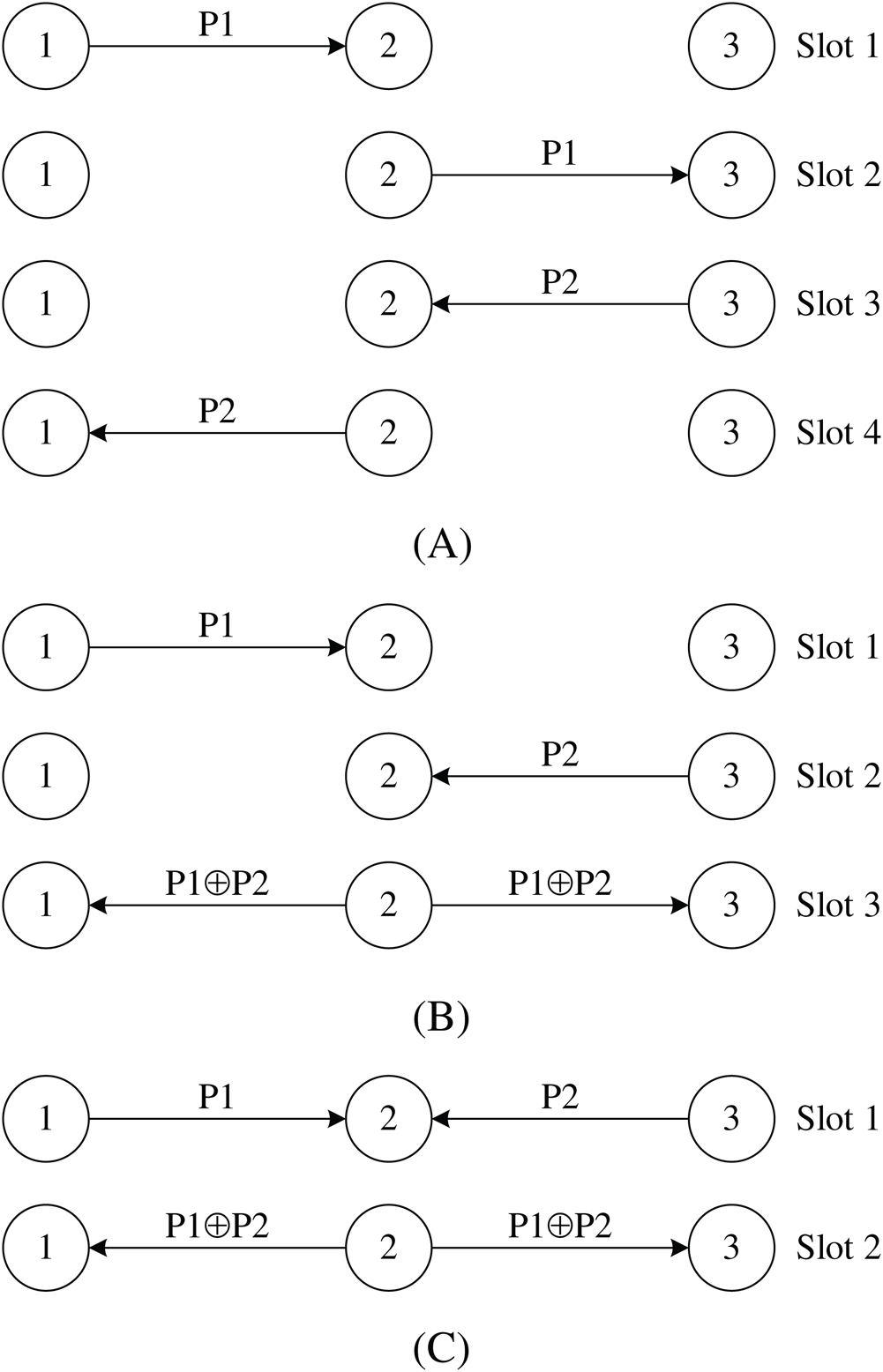
Figure 1: Illustration of physical layer network coding. (A) Store-forward manner, (B) network layer network coding manner, (C) physical layer network coding manner
Nevertheless, if network layer network coding is exploited, 3 time slots are required as shown in Fig. 1(B). Node 1 sends P1 and node 3 sends P2 both to node 2 consuming 1 time slot respectively. Then node 2 codes P1 and P2 (XOR operation) and sends out  . Due to the broadcast nature of the wireless channel, node 1 will receive
  and obtain P2 through decoding operation
  . Similarly, node 3 will obtain P1.
However, if physical layer network coding is exploited, the total number of time slots can be further reduced to 2. In slot 1, node 1 sends P1 and node 3 sends P2 simultaneously. The magnetic wave of P1 and P2 overlays in the space and forms the superimposed signal  . The overlaying can be considered as physical layer network coding operation. Then node 2 sends out
  . Node 1 will get P2 through decoding operation
  . Similarly, node 2 will obtains P1 as shown in Fig. 1(C).
It is evident from Fig. 1 that using physical network coding, the number of time slots is reduced by 50% compared with the store-forward mode, and reduced by 33% compared with the network layer network coding. Physical layer network coding can reduce data transmission time and improve transmission efficiency.
In RFID system, when tag collision occurs, the conflicting signal is the superposition of multiple tags’ signals, which can exactly be treated as physical layer network coding operation. However, traditional RFID tag anti-collision algorithms discard conflicting signals, which can be used for decoding to obtain original tag information. Therefore, the characteristics of physical layer network coding make it suitable for dealing with the tag collision problem of RFID system.
In this paper, a physical layer network coding based binary algorithm (PNBA) is proposed to solve multiple tags collision problem in RFID. Compared with existing mechanisms, PNBA exploits physical layer network coding to obtain information from the conflicting signal, which is discarded by the traditional method. Therefore, PNBA improves the tags identifying speed and reduce interaction costs between reader and tags. Simulation results demonstrate that, when the number of tags is 100, the average needed reading number of PNBA algorithm is 83% lower than that of BST, and 43% lower than that of RBST, and its reading efficiency is 0.93.
3.1 Conflicting Bit Recognition
To solve the tags collision problem, it is essential for the PNBA algorithm to judge whether there exits collision in the received signal, and further detects which bit occurs collision. As other binary algorithms, the PNBA algorithm exploits the Manchester code. Fig. 2 illustrates an example of the conflicting bits identification when signals of three tags are superimposed.
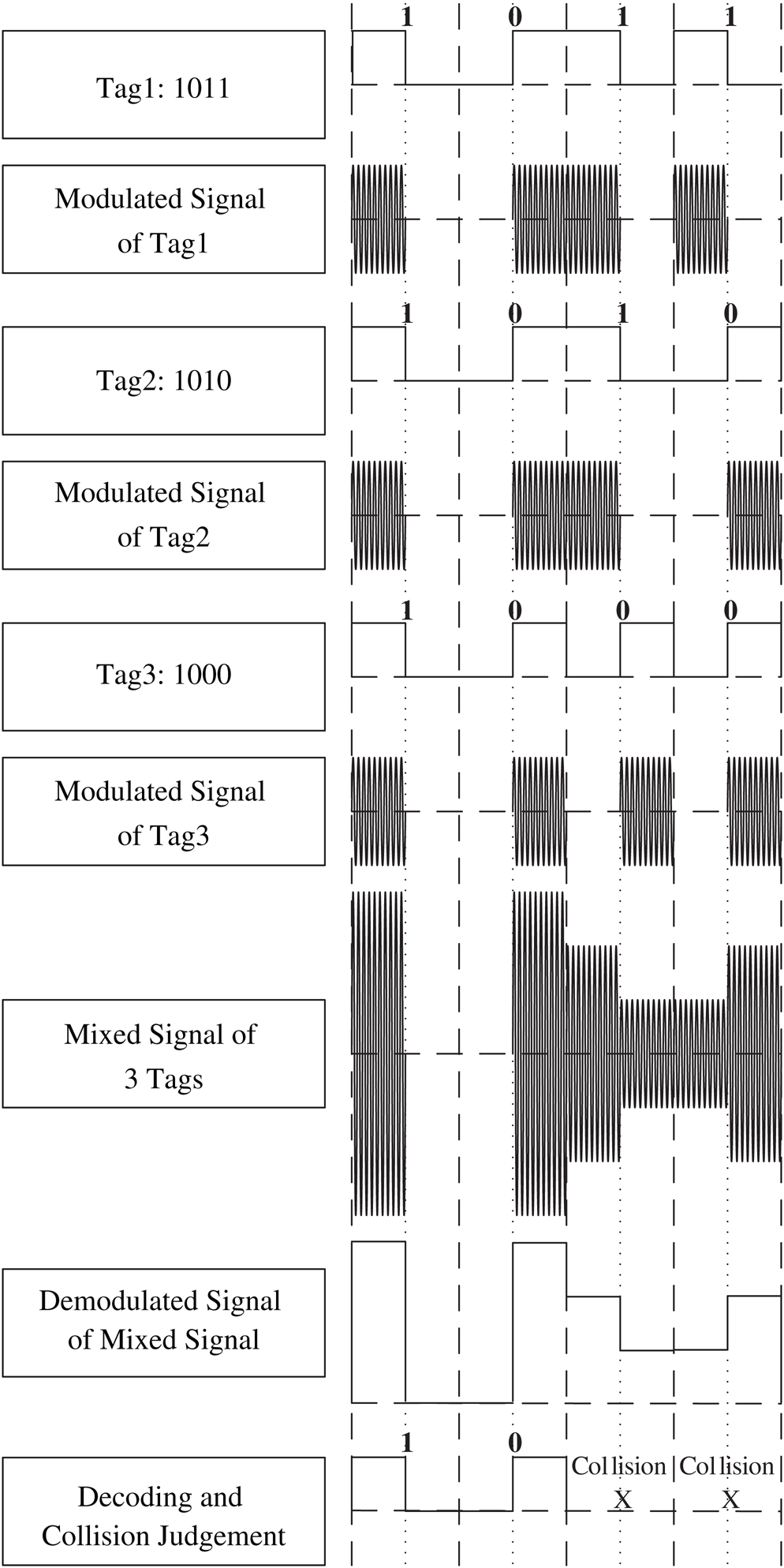
Figure 2: Illustration of conflicting bit identification using Manchester Code
It can be found from Fig. 2 that PNBA algorithm needs to check the first half and latter half of each bit in the superimposed signal to identify the conflicting bits. In Manchester code, ‘01’ represents the original information ‘0’, and ‘10’ represents the original information ‘1’. Using the Manchester code, the overlaying of multiple ‘01’ or multiple ‘10’ still ensure a half bit is 0. Therefore, if the first half or the latter half is zero, then there is no conflicting in this bit. Otherwise, conflict occurs in this bit, which is marked with “X”.
Before delving into the introduction of the detailed process of the PNBA algorithm, related concepts and commands used in the PNBA algorithm are presented.
Request Command: REQ(RSN)
Request command which contains reference sequence number (RSN), is sent by reader to tags. The tag whose sequence number is larger than RSN does not respond the command, while the tag whose sequence number is less than or equal to RSN will respond. In this way, the number of conflicting tags will be reduced.
Select Command: SEL(RSN)
Select command is sent by the reader. The tag whose sequence number is equal to RSN will be selected by the reader to prepare for subsequent reading and writing operations.
Read Command: RD-DATA
Read command means that the reader reads the sequence number returned by the selected tag.
Sleep Command: UNSEL(RSN)
The status of the tag whose sequence number is equal to the RSN, is set SLEEP, which means the tag will no longer respond to the reader’s any command.
Conflicting Stack:
In the PNBA algorithm, the reader maintains a conflicting information stack, which is used to store the overlapping conflict signal information of multiple tags.
PNBA algorithm introduces physical layer network coding into the RFID tag anti-collision algorithm. PNBA analyses and uses the conflict signal information discarded by the traditional tag anti-collision algorithm, which improves the efficiency of tag identification. The detailed process of PNBA is as follows.
Step 1. Initialize RSN and each bit of RSN is set to 1. For example, if the sequence number of a tag is 8 bits, the RSN is initialized as 11111111. Then initialize the backward variable i, which is set 0.
Step 2. The reader sends Request Command, REQ(RSN). The tag whose sequence number is less than or equal to RSN will respond and return its sequence number.
Step 3. Receiving magnetic waves, the reader will demodulate the received signal and detect whether conflict occurs in the received signal according to the Manchester Code principle. If the first half and the second half of a bit in the received signal are not zero, conflicting occurs in this bit. And it also means that the received signal contains conflicting. The conflicting signal is pushed into the Conflicting Stack. Find the highest conflicting bit in the conflicting signal and set it as 0. In addition, the bits lower than these bits are all set to 1, and the bits higher than these bits remain unchanged. Then the new modified conflicting signal is used as the RSN parameter of the next Request Command and Step 2 is executed. If the first half and the second half of each bit, one is high level, another is zero, there is no conflict in the received signal.
Step 4. The reader sends Select Command SEL(RSN). The tag whose ID equals to RSN, responds and returns its ID to the reader.
Step 5. The Read Command RD-DATA is executed by the reader to read and save the tag’s ID. Then the reader sends Sleep Command UNSEL(RSN), and the tag whose ID has just been read will be set SLEEP.
Step 6. Detect whether the Conflicting Stack is empty. If the stack is empty, it indicates that all the tags’ information has been read, and PNBA algorithm ends. Otherwise, the reader pops the element at the top of the Conflicting Stack and uses it minus the tag information the reader just read (decoding operation of physical layer network coding). Besides,  .
.
Step 7. Detect whether the result of the subtraction operation contains conflicting according to the Manchester Code. If the subtraction result contains conflicting, Step 8 is executed. If there is no conflicting in the subtraction result, it indicates that the subtraction result is one tag’s ID. The reader obtains the tag’s ID through physical network coding and will send SLEEP Command and let the tag enter the SLEEP state. Pop-up the element at the top of the Conflicting Stack, and Step 6 is executed. If each bit of the subtraction result is zero, it indicates that all the conflicting tags of the conflicting signal have been correctly read. Pop-up the top element of the Conflicting Stack, and Step 6 is executed.
Step 8 The RSN used in last ith interaction between reader and tag is taken as the parameter of the next Request Command REQ(RSN). i is reset to 0. Return to Step 2 until all tags are correctly read.
The flow chart of the PNBA algorithm is shown in Fig. 3.
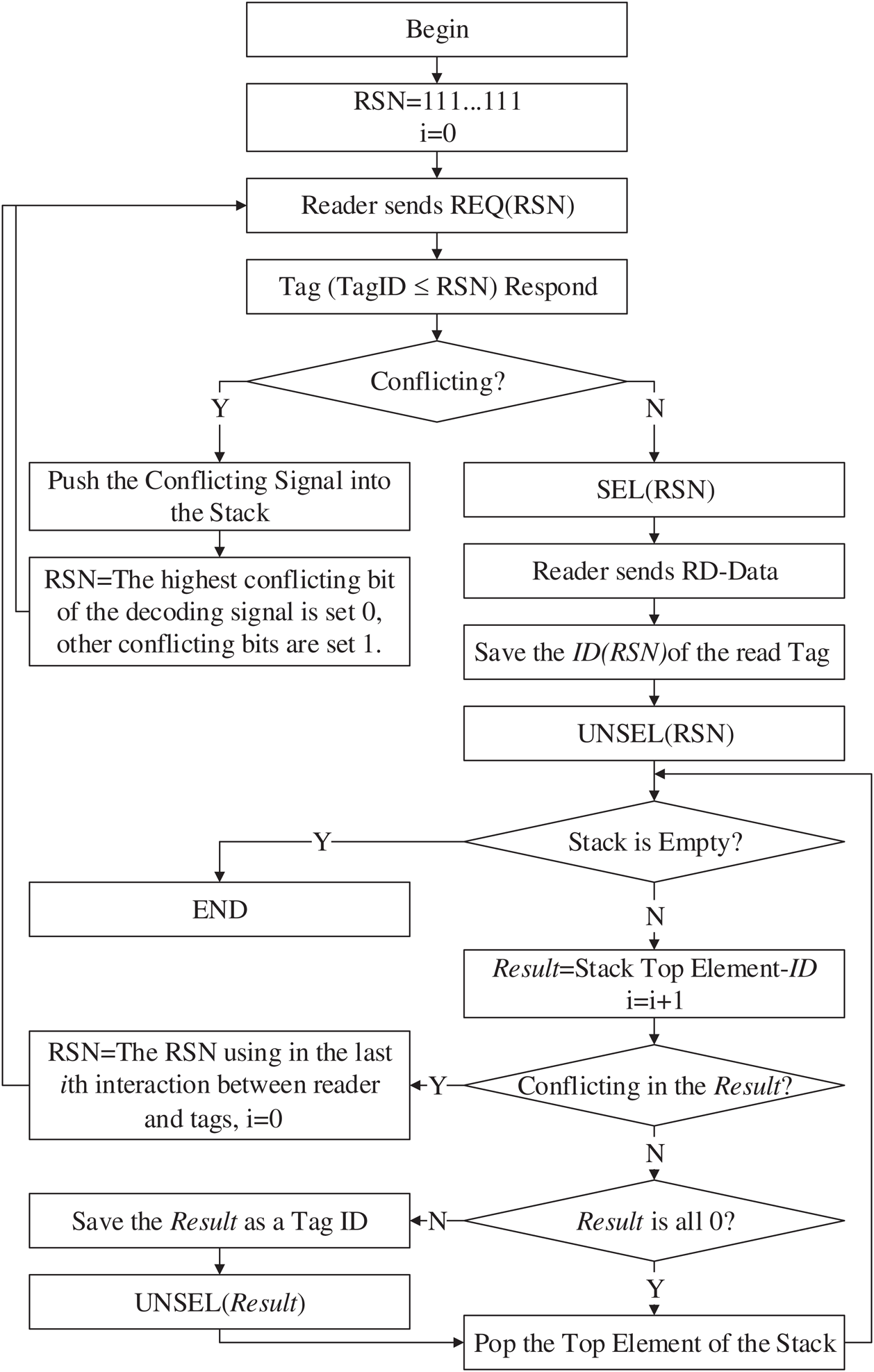
Figure 3: Flow chart of PNBA
3.4 An Application Example of PNBA
In order to clearly illustrate the principles of PNBA, an example scenario is given to analyse the working process of the PNBA. In this scenario, there is a reader and 4 tags in its working range: Tag1, Tag2, Tag3 and Tag4. The ID of each tag is formulated as D7D6D5D4D3D2D1D0 with 8 bits and is as follows: Tag1 with ID = 10110010, Tag2 with ID =10100011, Tag3 with ID = 10110011 and Tag4 with ID = 11100011. Then PNBA is executed:
1.Initial RSN is set 11111111. The reader sends REQ(11111111) and all 4 tags return their IDs. According to Manchester Coding, the reader receives 1X1X001X(X means conflicting bit.), which means there occurs collision and the conflicting demodulation signal  is pushed into the Conflicting Stack. And D6 is the highest collision bit. Therefore, D6 is set 0 and all bits lower than D6 are set 1 and the next RSN is 10111111.
2.The reader sends REQ(10111111). Tag1, Tag2 and Tag3, whose ID is less than 10111111 respond and return their IDs. The reader receives 101X001X. Since collision still occurs, the conflicting demodulation signal  is pushed into the Conflicting Stack. D4 is the highest bit with collision. Therefore, D4 is set 0 and all bits lower than D4 are set 1 and the next RSN is 10101111.
3.The reader sends REQ(10101111), and only Tag2 returns its ID. The reader demodulates and decodes the received signal and gets 10100011 which contains no collision. The reader identifies Tag2 correctly and send SLEEP(10101111) to let Tag2 enter the state of SLEEP.
4.The reader sends REQ(10111111). Tag1 and Tag3 return their IDs. The reader demodulates and decodes the received signal and gets 1011001X. Since collision occurs at D0, the conflicting demodulation signal  is pushed into the Conflicting Stack. D0 is set 0 and 10110010 is the parameter of the next REQ(RSN).
5.The reader sends REQ(10110010) and only Tag1 returns its ID. The reader demodulates and decodes the received signal and gets 10110010 which contains no collision. The reader identifies the Tag1 correctly and sends SLEEP(10110010) to let the Tag1 enter into the state of SLEEP. The reader pops up the top element 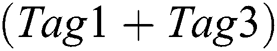 of the Conflicting Stack. The top element minus the 10110010(Tag1) and get 10110011 with no collision. The 10110011 is the ID of Tag3 obtained through physical layer network coding. The reader sends SLEEP(10110011) to let Tag3 enter into the state of SLEEP. The reader pops up top element
 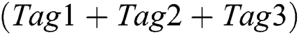 of the Conflicting Stack. Subtract the information of Tag1, Tag2 and Tag3 from the top element. And then the result is 00000000. The reader pops up top element
 of the Conflicting Stack. Subtract the information of Tag1, Tag2 and Tag3 from the top element. And then the result is 11100011. The 11100011 is just the ID of Tag4 obtained through physical layer network coding. So far, all the tags have been correctly obtained. It is obvious that only Tag2 and Tag1 are read by the reader, while the IDs of Tag3 and Tag4 are obtained by physical layer network coding, which reduces the number of reading times between reader and tags and improves reading efficiency.
Fig. 4 shows the entire recognition process of the example and the change of the demodulated signal stack.
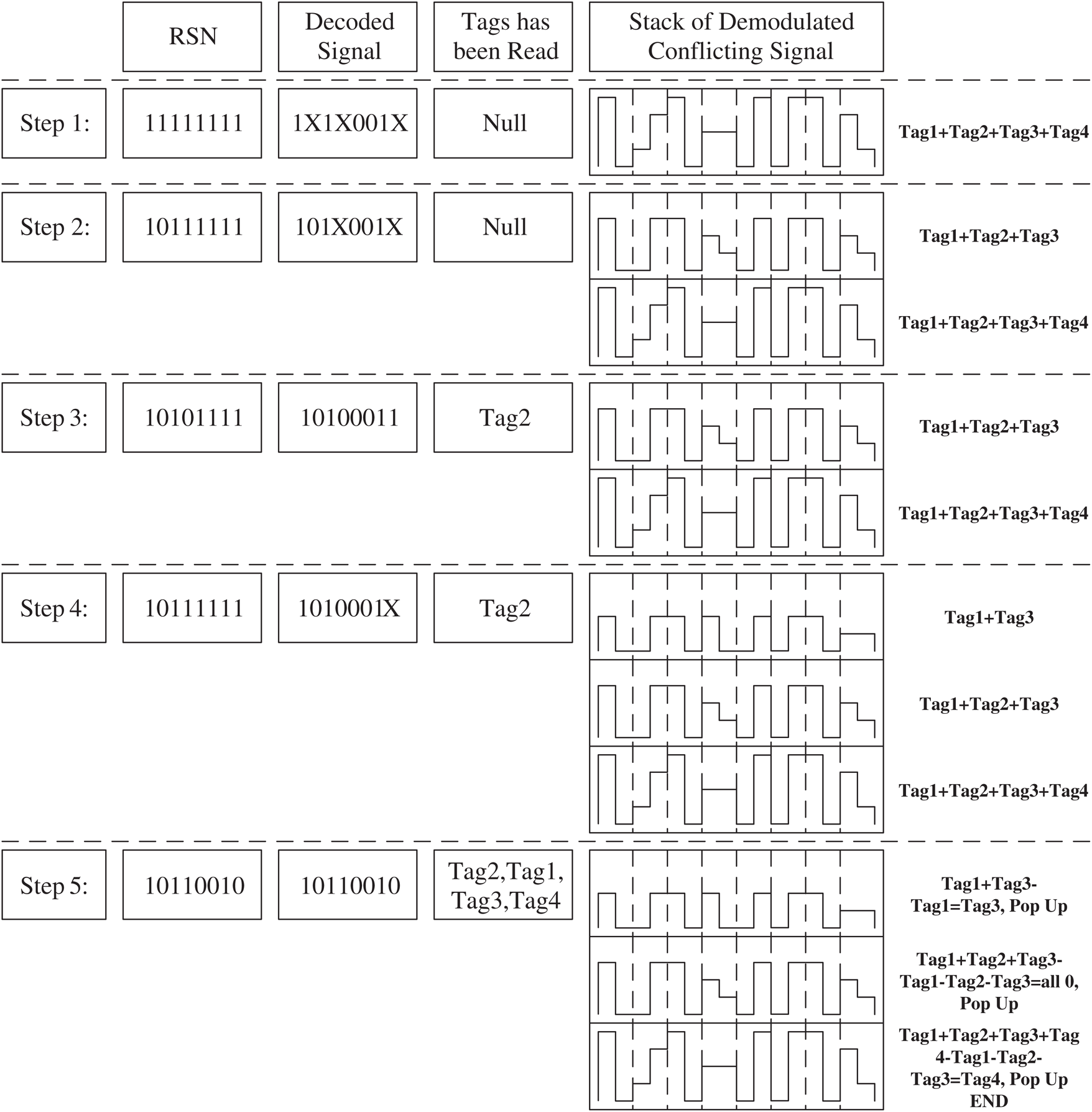
Figure 4: Application example of PNBA
4 Theoretical Analysis of PNBA
4.1 Theoretical Analysis of Reading Times
For binary search tree algorithm (BST), when there are N tags to be identified, the needed reading times for the first tag to be identified is  . Therefore, the number of the total needed reading times of BST (abbreviated as RT-BST) to identify all N tags is as Eq. (1).

Since the key process of the dynamic binary search tree algorithm (DBST) is similar to BST, the total number of reading times of DBST (abbreviated as RT-DBST) is the same as that of BST, and is shown in Eq. (2).

The process of regressive-style binary search tree algorithm (RBST) to identify N tags is equivalent to the complete search of binary tree with N node. Therefore, the required reading number of RBST is  .
.
For the PNBA algorithm, the required reading number to identify the first tag is  . Since the PNBA algorithm exploits physical layer network coding, the conflicting signals can be decoded layer by layer. For the rest
  tags, each tag only needs one time reading. Therefore, the total required reading time by the PNBA (abbreviated as RT-PNBA) is as Eq. (3).

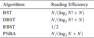
The comparison of the required reading number to identify N tags for the algorithms mentioned above is shown in Tab. 1.
Table 1: Comparison of reading times

The reading efficiency is defined as N divided by the reading times. The reading efficiency comparison of the algorithms is shown in Tab. 2.
Table 2: Comparison of reading efficiency
4.2 Theoretical Analysis of Transmission Bits Number
The transmission bit number is the bit number of each transmission multiplied by the transmission number. Assume N is the number of tags to be identified and K is the bit number of each tag. For DBST, the bit number of each transmission depends on the position of the conflicting bit. Assume the conflicting bit is random and the probability of collision at each bit is the same as  . Then, the expectation of each transmission bit number for DBST (abbreviated as TB-DBST) is as Eq. (4).

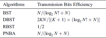
The transmission bits number comparison of the 4 algorithms is shown in Tab. 3.
Table 3: Comparison of transmission bits number

The transmission efficiency is defined as  divided by the expectation of transmission bit number. The transmission efficiency comparison of the 4 algorithms is shown in Tab. 4.
Table 4: Comparison of transmission efficiency
In order to analyze the performance of the PNBA algorithm, the BST, DBST, RBST and PNBA are simulated using MATLAB.
Fig. 5 shows the required reading times for the four algorithms when the number of tags to be identified is between 5 and 100. It is clear that BST and DBST are always the same. Compared with BST and DBST, RBST is significantly lower, and the advantage is more obvious with the increasing of the tags’ number. When the number of tags to be identified is less than 25, PNBA is close to RBST. When the number of tags to be identified is greater than 25, the required reading number of PNBA is significantly lower than that of RBST, and the advantage is more obvious with the growth of the tags’ number. When the number of tags is 100, the PNBA is 45% lower than RBST.
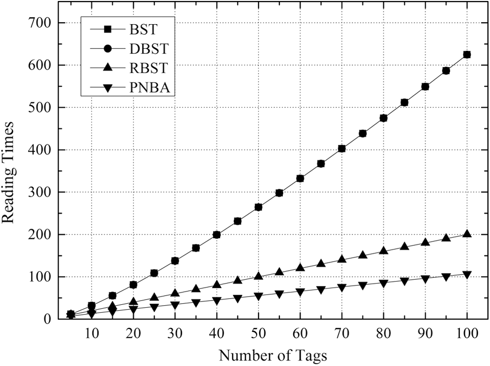
Figure 5: Comparison of required reading times under different number of tags to be identified for 4 algorithms
Fig. 6 illustrates the comparison of reading efficiency when the tags number to be identified is between 5 and 100 for the 4 algorithms. The so-called read efficiency is calculated as the number of tags divided by the number of required reading times. It is evident from Fig. 6 that the PNBA algorithm is more efficient than the other 3 algorithms. BST and DBST are always the same. When the number of tags is between 5–40, BST and DBST gradually reduce to 0.2, and RBST is always maintained at 0.5. However, the PNBA algorithm gradually increases to 0.8. When the number of tags is larger than 40, the reading efficiency of the 4 algorithms changes slowly. BST and DBST are between 0.16–0.19, PNBA is between 0.89–0.93, and RBST is at 0.5.
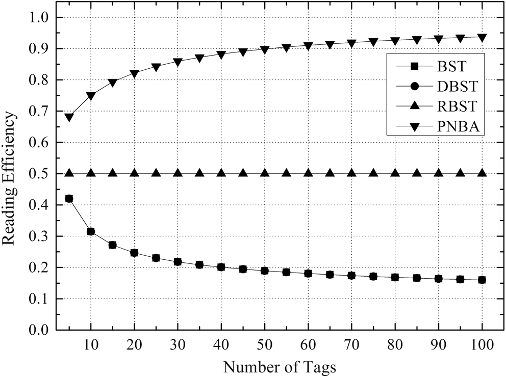
Figure 6: Comparison of reading efficiency under different number of tags to be identified for 4 algorithms
Figs. 7–10 illustrates the number comparison of needed transmission bits number when the tags’ number to be identified is between 5 and 100 for the 4 algorithms under K = 8, K = 16, K = 24 and K = 32 respectively.
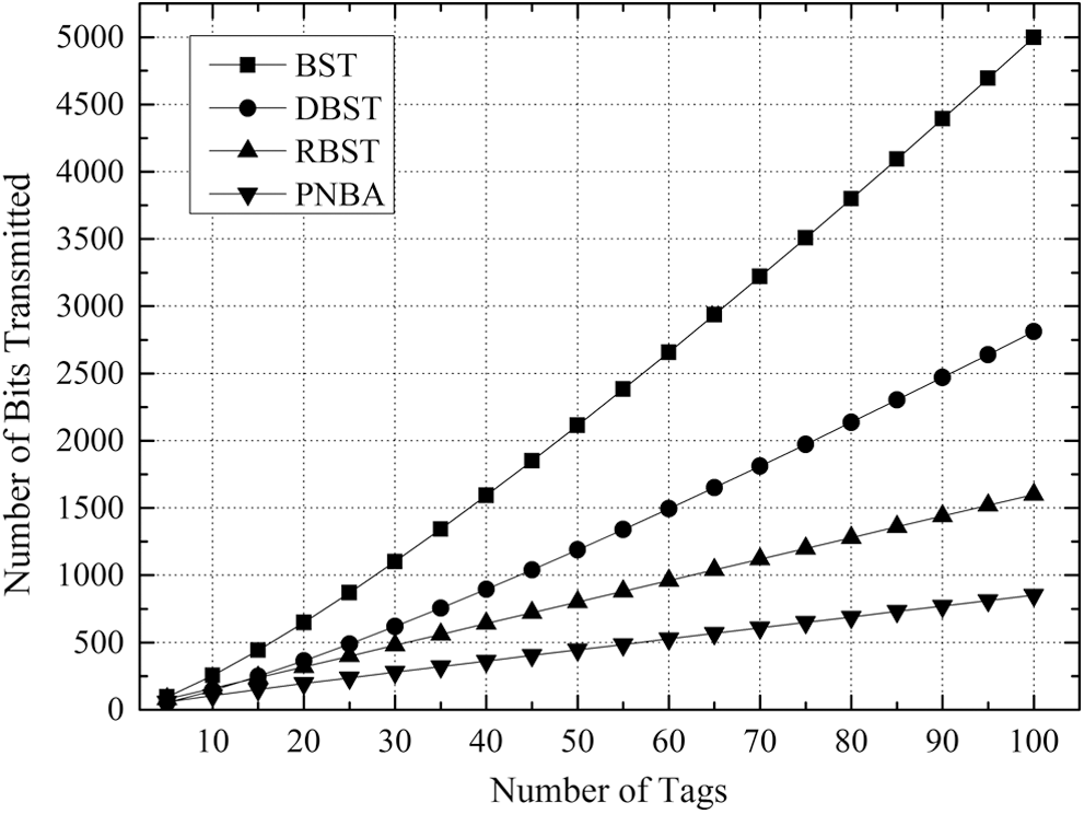
Figure 7: Comparison of number of bits transmitted of 4 algorithms with K = 8 for DBST
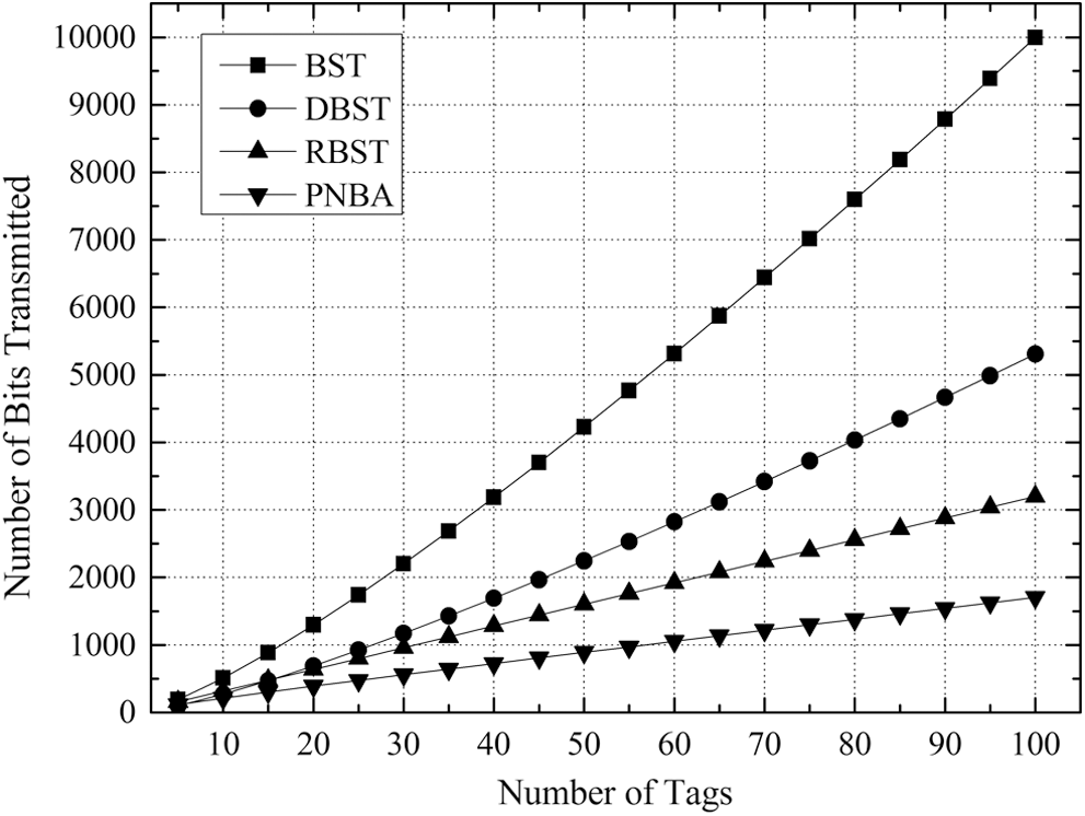
Figure 8: Comparison of number of bits transmitted of 4 algorithms with K = 16 for DBST
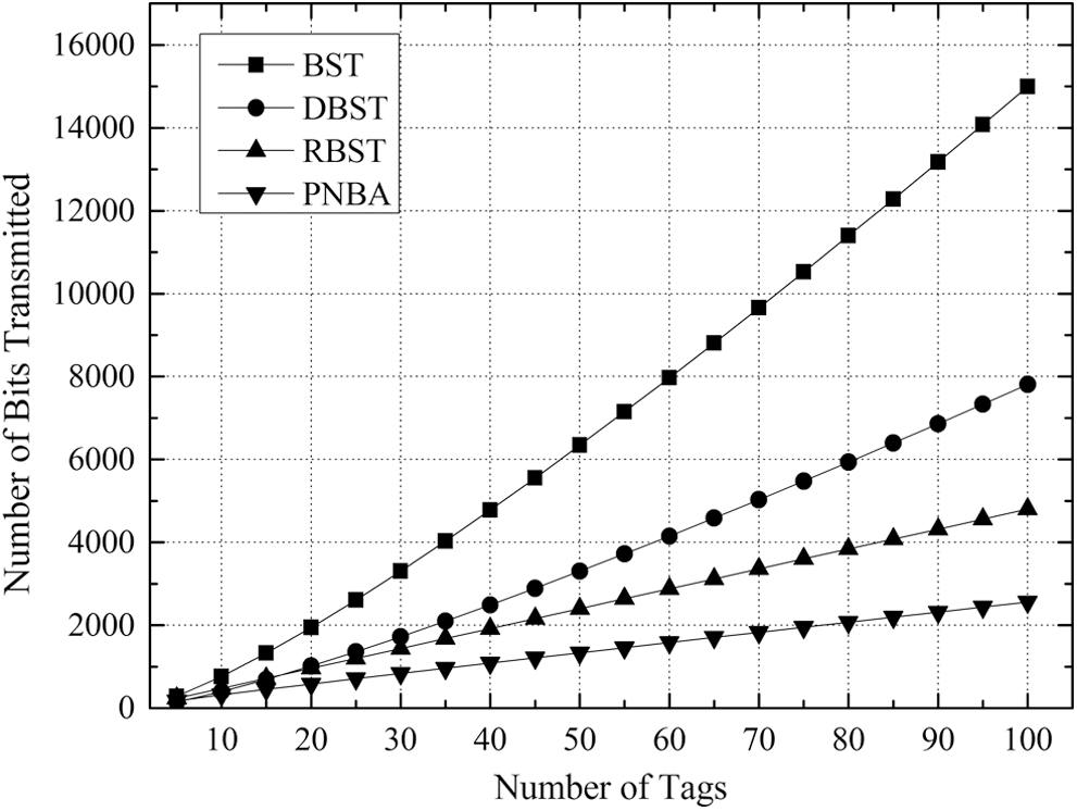
Figure 9: Comparison of number of bits transmitted of 4 algorithms with K = 24 for DBST
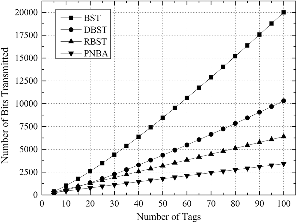
Figure 10: Comparison of number of bits transmitted of 4 algorithms with K = 32 for DBST
It can be found that in the cases with different values of K, the relative relationship and changing trend of the 4 algorithms in the transmission bit number is consistent.
With the increase of the tags number to be identified, the needed transmission bits number for the 4 algorithms increases gradually. And the gap between the 4 algorithms is widened gradually. Besides, with the growing of K value, the gap between the 4 algorithms increases gradually as well.
It is clear from Figs. 7–10 that BST needs the greatest transmission bits number, DBST takes the second place. Since RBST can reduce the transmitted bits number of each identifying procedure, it is lower than DBST, but higher than PNBA. The reason is that PNBA needs lower identifying number than RBST, and PNBA can exploit the conflicting information in the stack to avoid the transmission of a large number of duplicate data. PNBA is always the lowest under the different K values.
Fig. 11 depicts the comparison of the transmission efficiency of the 4 algorithms when the number of tags to be identified is between 5 and 100. According to Tab. 4, the transmission efficiency of DBST is only related to the value of K. Therefore, the simulations of DBST under K = 8, 16, 24, 32 are carried out respectively. The so-called transmission efficiency is calculated as K × N divided by the total number of transmission bits. It is obvious from Fig. 11 that the relationship of BST, RBST and PNBA in transmission efficiency is consistent with that in reading efficiency from Fig. 6, and PNBA is greater than BST and RBST significantly. When the tag number is 5, DBST is higher than PNBA, DBST with K = 8 is 9% greater than PNBA, DBST with K = 32 is 19% greater than PNBA.
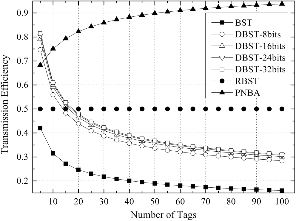
Figure 11: Comparison of the transmission efficiency of the 4 algorithms
However, with the increase of tags number, DBST declines dramatically. When the tags number is 15, DBST is lower than PNBA and close to RBST. The reason is the sharp increase in the number of transmissions required by the DBST with the increase of the tags number. When the tags number is greater than 15, the DBST is less than RBST. And for DBST with different K values, the greater the value of K, the higher the transmission efficiency is. However, the greater the K value, the smaller the improvement of the transmission efficiency. As shown in Fig. 11, DBST with K = 8 is significantly lower than that of the DBST with K = 16, while the transmission efficiency is close for the DBST with K = 16, 24, 32.
Aiming the multiple tags collision problem in the RFID system, this paper exploits physical layer network coding and presents physical layer network coding based binary search tree algorithm (PNBA). In PNBA, the multiple tags collision signal is exploited to reduce the times of identifying and improve reading efficiency. In addition, the physical layer network coding usually needs strict synchronization. The decoding of multiple tags conflicting information with non-strict synchronization will be the future work.
Acknowledgement: The authors wish to thank anonymous reviewers for their valuable comments and suggestions for the improvement of this paper.
Funding Statement: This work was supported by the National Natural Science Foundation of China under Grant 61502411; Natural Science Foundation of Jiangsu Province under Grant BK20150432 and BK20151299; Natural Science Research Project for Universities of Jiangsu Province under Grant 15KJB520034; China Postdoctoral Science Foundation under Grant 2015M581843; Jiangsu Provincial Qinglan Project; Teachers Overseas Study Program of Yancheng Institute of Technology; Jiangsu Provincial Government Scholarship for Overseas Studies; Talents Project of Yancheng Institute of Technology under Grant KJC2014038; “2311” Talent Project of Yancheng Institute of Technology; Open Fund of Modern Agricultural Resources Intelligent Management and Application Laboratory of Huzhou Normal University.
Conflicts of Interest: The authors declare that they have no conflicts of interest to report regarding the present study.
References
1E. Ilie-Zudor, Z. Kemeny, F. Van Blommestein, L. Monostori and A. Van Der Meulen. (2011), “A survey of applications and requirements of unique identification systems and RFID techniques. ,” Computers in Industry, vol. 62, no. (3), pp, 227–252, .
2V. Elia and M. G. Gnoni. (2013), “Pervasiveness of RFID technology: A survey based on case studies analysis. ,” International Journal of RF Technologies: Research and Applications, vol. 5, no. (1–2), pp, 41–61, . [Google Scholar]
3J. Su, Z. Sheng, V. C. M. Leung and Y. Chen. (2019), “Energy efficient tag identification algorithms for RFID: Survey, motivation and new design. ,” IEEE Wireless Communications, vol. 26, no. (3), pp, 118–124, . [Google Scholar]
4D. K. Klair, K. W. Chin and R. Raad. (2010), “A survey and tutorial of RFID anti-collision protocols. ,” IEEE Communications Surveys & Tutorials, vol. 12, no. (3), pp, 400–421, .
5L. Zhu and T. S. P. Yum. (2011), “A critical survey and analysis of RFID anti-collision mechanisms. ,” IEEE Communications Magazine, vol. 49, no. (5), pp, 214–221, . [Google Scholar]
6Z. Qian and X. Wang. (2014), “An overview of anti-collision protocols for radio frequency identification devices. ,” China Communications, vol. 11, no. (11), pp, 44–59, . [Google Scholar]
7V. Namboodiri, M. Desilva, K. Deegala and S. Ramamoorthy. (2012), “An extensive study of slotted Aloha-based RFID anti-collision protocols. ,” Computer Communications, vol. 35, no. (16), pp, 1955–1966, . [Google Scholar]
8Z. G. Prodanoff. (2010), “Optimal frame size analysis for framed slotted ALOHA based RFID networks. ,” Computer Communications, vol. 33, no. (5), pp, 648–653, . [Google Scholar]
9H. Wu and Y. Zeng. (2011), “Efficient framed slotted Aloha protocol for RFID tag anti-collision. ,” IEEE Transactions on Automation Science and Engineering, vol. 8, no. (3), pp, 581–588, .
10L. Arjona, H. Landaluce, A. Perallos and E. Onieva. (2020), “Dynamic frame update policy for UHF RFID sensor tag collisions. ,” Sensors. (Switzerland), vol. 20, no. (9), pp, 1–17, . [Google Scholar]
11Y. Chen, Q. Feng, M. Zheng and L. Tao. (2013), “Multiple-bits-slot reservation aloha protocol for tag identification. ,” IEEE Transactions on Consumer Electronics, vol. 59, no. (1), pp, 93–100, . [Google Scholar]
12Z. Huang, J. Su, G. Wen, W. Zheng, C. Chu et al. (2019). , “A physical layer algorithm for estimation of number of tags in UHF RFID anti-collision design. ,” Computers, Materials & Continua, vol. 61, no. (1), pp, 399–408, . [Google Scholar]
13J. Su, Z. Sheng, L. Xie, G. Li and A. X. Liu. (2019), “Fast splitting-based tag identification algorithm for anti-collision in UHF RFID system. ,” IEEE Transactions on Communications, vol. 67, no. (3), pp, 2527–2538, . [Google Scholar]
14X. Q. Yan, Y. Liu, B. Li and X. M. Liu. (2015), “A memoryless binary query tree based successive scheme for passive RFID tag collision resolution. ,” Information Fusion, vol. 22, no. (3), pp, 26–38, . [Google Scholar]
15Y. J. Ren, F. Zhu, P. K. Sharma, T. Wang, J. Wang et al. (2020). , “Data query mechanism based on hash computing power of blockchain in Internet of Things. ,” Sensors, vol. 20, no. (1), pp, 1–22, . [Google Scholar]
16Y. C. Lai, L. Y. Hsiao and B. S. Lin. (2013), “An RFID anti-collision algorithm with dynamic condensation and ordering binary tree. ,” Computer Communications, vol. 36, no. (17–18), pp, 1754–1767, . [Google Scholar]
17J. Zhang, Z. Z. Li, X. Zhang, Z. C. Lei and Z. X. Mei. (2010), “Anti-collision algorithm based on the regressive style RFID of BIBD(4,2,1). ,” in Proc. ICACTE, Chengdu, China: , pp, 4352–4355, . [Google Scholar]
18X. Chen, G. Liu, Y. Yao, Y. Chen, S. Miao et al. (2010). , “IRBST: An improved RFID anti-collision algorithm based on regressive-style binary search tree. ,” in Proc. IFITA, Kunming, China: , pp, 403–406, . [Google Scholar]
19R. Bossoli, H. Marques, J. Rodriguez, K. W. Shum and R. Tafazolli. (2013), “Network coding theory: A survey. ,” IEEE Communications Surveys and Tutorials, vol. 15, no. (4), pp, 1950–1978, . [Google Scholar]
20Y. Ren, Y. Leng, Y. Cheng and J. Wang. (2019), “Secure data storage based on blockchain and coding in edge computing. ,” Mathematical Biosciences and Engineering, vol. 16, no. (4), pp, 1874–1892, . [Google Scholar]
21S. C. Liew, S. Zhang and L. Lu. (2013), “Physical-layer network coding: Tutorial, survey and beyond. ,” Physical Communication, vol. 6, no. (3), pp, 4–42, . [Google Scholar]
 | This work is licensed under a Creative Commons Attribution 4.0 International License, which permits unrestricted use, distribution, and reproduction in any medium, provided the original work is properly cited. |