
 Submit a Paper
 Propose a Special lssue
 Open Access
ARTICLE

Biomechanical Study of Different Scaffold Designs for Reconstructing a Traumatic Distal Femur Defect Using Patient-Specific Computational Modeling
1 Department of Orthopedics, School of Medicine, College of Medicine, Taipei Medical University, Taipei, 11031, Taiwan
2 Department of Orthopedics, Taipei Medical University Hospital, Taipei, 11031, Taiwan
3 Department of Mechanical Engineering, National Taiwan University of Science and Technology, Taipei, 10607, Taiwan
4 Graduate Institute of Applied Science and Technology, National Taiwan University of Science and Technology, Taipei, 10607, Taiwan
* Corresponding Author: Ching-Chi Hsu. Email:
(This article belongs to the Special Issue: Advances in Mathematical Modeling: Numerical Approaches and Simulation for Computational Biology)
Computer Modeling in Engineering & Sciences 2025, 142(2), 1883-1898. https://doi.org/10.32604/cmes.2025.057675
Received 24 August 2024; Accepted 25 December 2024; Issue published 27 January 2025
 View Full Text
 Download PDF
Abstract
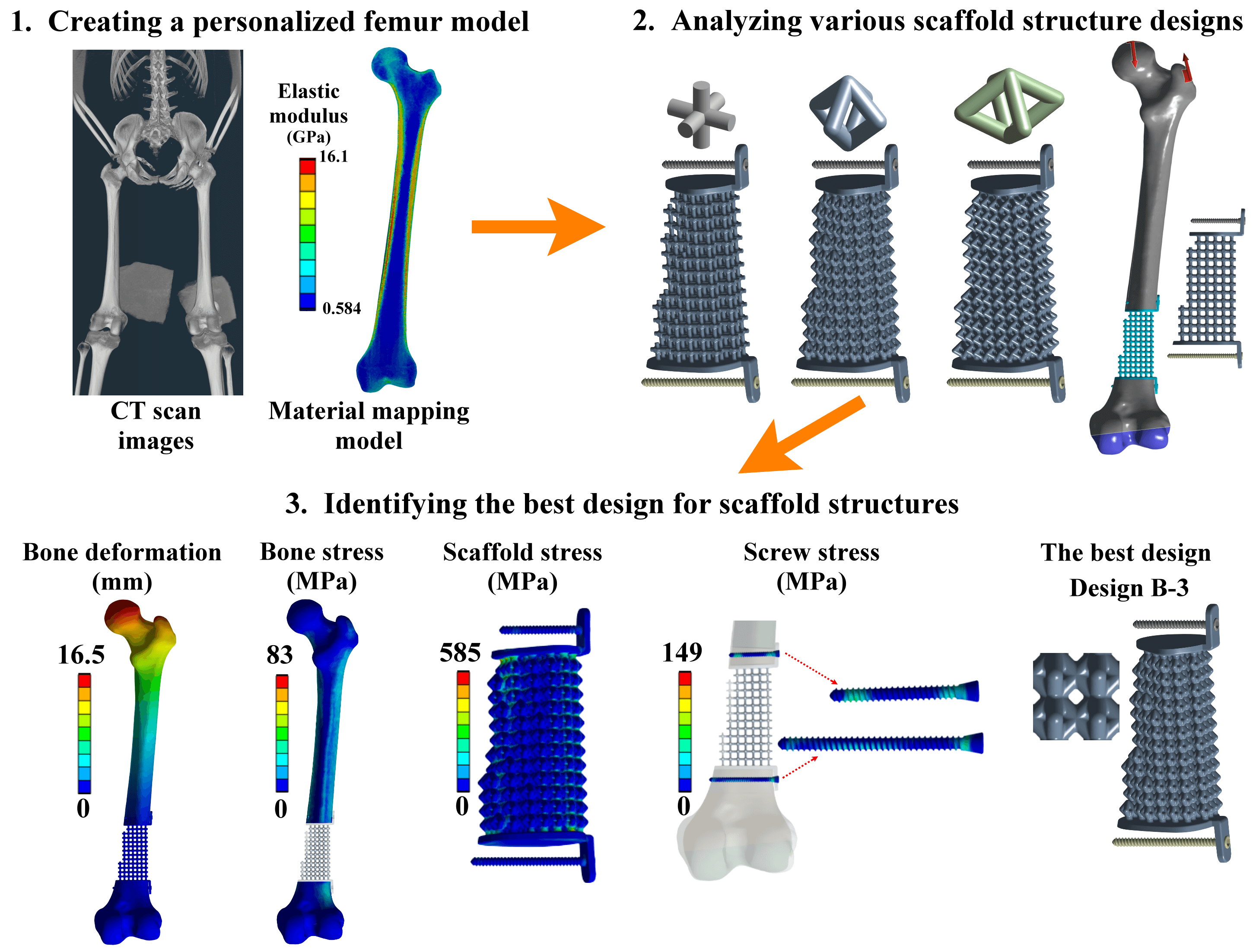
Reconstruction of a traumatic distal femur defect remains a therapeutic challenge. Bone defect implants have been proposed to substitute the bone defect, and their biomechanical performances can be analyzed via a numerical approach. However, the material assumptions for past computational human femur simulations were mainly homogeneous. Thus, this study aimed to design and analyze scaffolds for reconstructing the distal femur defect using a patient-specific finite element modeling technique. A three-dimensional finite element model of the human femur with accurate geometry and material distribution was developed using the finite element method and material mapping technique. An intact femur and a distal femur defect model treated with nine microstructure scaffolds and two solid scaffolds were investigated and compared under a single-leg stance loading. The results showed that the metal solid scaffold design could provide the most stable fixation for reconstructing the distal femur defect. However, the fixation stability was affected by various microstructure designs and pillar diameters. A microstructure scaffold can be designed to satisfy all the biomechanical indexes, opening up future possibilities for more stable reconstructions. A three-dimensional finite element model of the femur with real bone geometry and bone material distribution can be developed, and this patient-specific femur model can be used for studying other femoral fractures or injuries, paving the way for more comprehensive research in the field. Besides, this patient-specific finite element modeling technique can also be applied to developing other human or animal bone models, expanding the scope of biomechanical research.Graphic Abstract
Keywords
Road traffic accidents are one of the reasons that cause long bone trauma [1,2]. Approximately 10% of traffic accidents cause femoral fractures [3]. Femoral fractures are classified into different types based on fracture site and pattern. Patients with simple femoral fractures have been treated using interlocking nails [4–6] or locking compression plates [7–9]. However, complex or comminuted femoral fractures might cause bone defect problems [10]. The interlocking nails and locking compression plates might have difficulty fixing these unstable complex femoral fractures. Bone defect implants have been designed and used to restore femoral bone defects [10,11]. Metal and solid-based bone defect implants have high structure rigidity and produce good fixation stability. However, their high structure rigidity would lead to stress shielding problems [12,13]. Non-metal materials, such as Polyether–Ether–Ketone (PEEK), are another choice to reduce the stress shielding effect. A past study found that the femur with the PEEK implant showed a more natural stress distribution than the femur with the Ti6Al4V implant [14].
Another way to reduce the stress shielding effect is to use additive manufacture-based microstructure scaffolds [15,16]. Different microstructure designs have different stress-strain relations and mechanical properties [17]. In-vitro experiments have been used to investigate the mechanical properties of the microstructure designs [18–20]. This experimental testing method can clarify the microstructure designs’ mechanical properties before clinical application, but high experimental variations are the potential problem [21]. In-silico studies can solve the problem of high experimental variations, but modeling simplification is a possible problem. The main issue for in-silico studies is the assumption of bone material [22,23]. A uniform thickness for cortical shells and constant material distribution for both cortical and cancellous bones have been ideally used. However, the assumption of bone material properties affects the results of treatment strategies or fixation device evaluations. This study emphasizes the need for accurate bone material distribution and properties in in-silico studies, which is necessary for reliable results [24,25]. Thus, this study aimed to investigate the biomechanical performance of various scaffold structure designs in reconstructing a traumatic distal femur defect using a patient-specific finite element analysis.
2.1 Development of a Patient-Specific Femur Model
Computed tomographic (CT) scan images are required data to construct a patient-specific model. The public CT scan image data of the human male right femur from the National Institutes of Health’s (NIH) Visible Human Project were used. The CT scan data were taken at 1 mm intervals at a resolution of 512
In addition to the femur’s geometry, bone material is another important data for developing the patient-specific femur model. The Hounsfield unit values of the femur from the CT data were determined and recorded using self-developed Python scripting within Amira-Avizo software. The Young’s modulus of the femur was estimated from the Hounsfield unit values based on the following relationships proposed by the past study [26]:
where
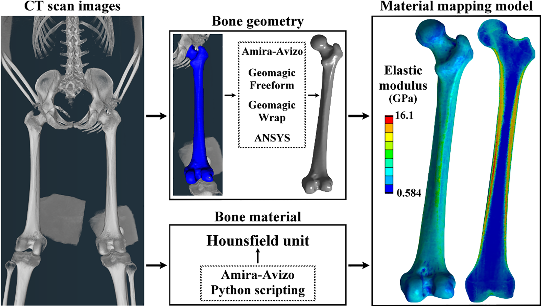
Figure 1: The patient-specific femur model development using bone geometry and material data
2.2 A Distal Femur Defect Model and a Treated Femur Model
A distal femur defect model was developed by removing the partial distal region of the intact femur. This bone defect was created to mimic traumatic fracture or bone loss due to tumor resection. The bone defect size was 82 mm (Fig. 2A). A bone defect implant was designed to support the human body weight. This bone defect implant is composed of a scaffold structure, two connection plates, and two screws (Fig. 2B). The scaffold structure was designed using pillars with different connection designs and diameters. The detailed scaffold structure designs were defined later. The connection plates were designed to connect the injured femur and the scaffold structure. To secure the scaffold-plate structure, two locking screws were developed. The locking screws feature a buttress thread with an outer diameter of 4 mm, an inner diameter of 3 mm, and a pitch of 1.48 mm. The lengths of the screws are 40 mm for the proximal screw and 55 mm for the distal screws. All the scaffold structures, connection plates, and locking screws were developed using ANSYS DesignModeler with a basic model construction technique and Boolean operation method. The scaffold-plate structure was implanted into the injured femur and secured by the two locking screws.
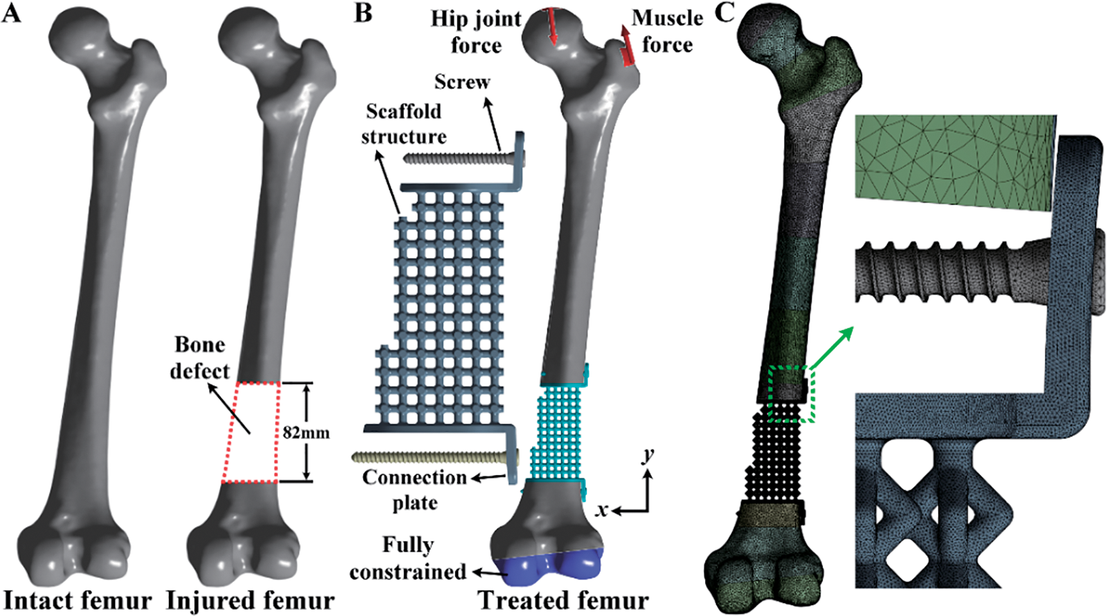
Figure 2: (A) Development of the model for a distal femur defect starting from the intact femur; (B) The boundary and loading conditions of the model for the distal femur defect treated with the scaffold and screws; (C) The finite element mesh of the distal femur defect model with the scaffold and screws
Three-dimensional finite element models of the intact femur and the injured femur treated with various bone defect devices were developed and analyzed using ANSYS Workbench. The femur’s material was assigned based on the Hounsfield unit values of the CT scan images. This assignment used a linear elastic isotropic material model with a Poisson’s ratio of 0.3 for each femur element. The material of the scaffold-plate construct and locking screws was titanium alloy (Ti6Al4V). It has a Young’s modulus of 113.8 GPa, a Poisson’s ratio of 0.342, and a yield strength of 880 MPa [27]. In the boundary and loading conditions, the exterior surfaces of the distal femur were fully constrained. The hip joint and gluteal medius muscle forces were applied to the proximal femur (Fig. 2B). The detailed definition of the loadings is listed in Table 1 [28–30]. These loadings simulated a static single-leg stance scenario.

The interface between the locking screws and the femur was assumed to be bonded. This interface condition was used to mimic the screws fastening on the femur. The interface between the connection plates and the femur was also assumed to be bonded. This interface condition mimicked the bone ingrowing into the connection plates. The femur and the bone defect implant were free-meshed for the mesh strategy and convergence analysis using 10-node tetrahedral elements (Fig. 2C). The element size for the femur and the bone defect implant was determined according to the convergence analysis results. The convergence criterion of the finite element study was set to be less than 15%. In post-processing, the maximum total deformation of the intact and injured femurs, the maximum von Mises stress of the scaffolds, the maximum von Mises stress of the locking screws, and the maximum von Mises stress of the intact and injured femurs were analyzed and discussed.
2.4 Various Scaffold Structure Designs
Three types of microstructure scaffold designs were developed, and each single microstructure has a bounding box with 6 mm in length, width, and height. Design A is composed of six pillars, and each pillar is connected between the body center and the face center of the bounding box. Design B comprises eight pillars, and all the pillars are connected at the face center of the bounding box. Design C is also composed of eight pillars. Two connection points of the pillars are at the face center of the bounding box on the top and bottom faces. The other connection points of the pillars are at the edge center of the bounding box. To eliminate or reduce high-stress concentration on three microstructure scaffold designs, all sharp edges of the scaffold designs were fillet with a 1 mm radius (Fig. 3A). A pillar diameter of microstructure design has been used to control its structure rigidity [31]. In the present study, three different pillar diameters were used. Design A-1 has a pillar diameter of 1.5 mm, Design A-2 has a pillar diameter of 2.0 mm, and Design A-3 has a pillar diameter of 2.5 mm. The arrangement of the pillar diameters for Design B and Design C are the same as for Design A (Fig. 3A).
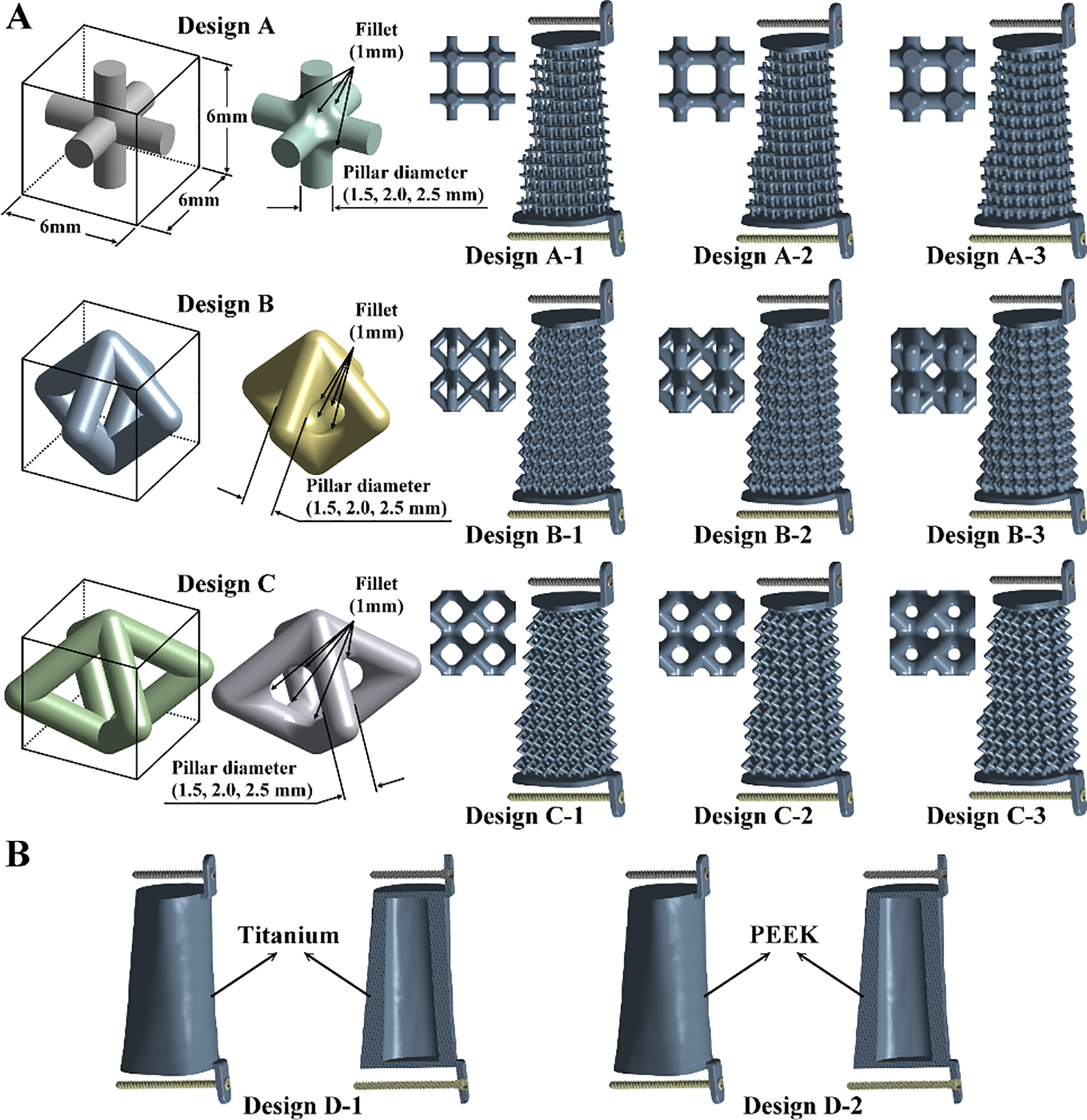
Figure 3: (A) Three types of microstructures with three different pillar diameters for the designs of scaffolds; (B) Two solid scaffold structure designs
Two solid scaffold structure designs were developed and analyzed to investigate the stress shielding effects (Fig. 3B). Design D-1 is the first type of solid scaffold structure design. Its geometry was mainly based on the intact femur, and a hollow structure with a thickness of 8 mm was constructed. The material of Design D-1 was made of titanium alloy (Ti6Al4V). The Young’s modulus, Poisson’s ratio, and yielding strength of Design D-1 are the same as the microstructure scaffold designs. The second type of solid scaffold structure design is Design D-2. It has the same geometry and structure as Design D-1. The material of Design D-2 was PEEK. It has Young’s modulus of 3.8 GPa, Poisson’s ratio of 0.362, and yield strength of 80 MPa [32,33].
3.1 Convergence Study of the Patient-Specific Finite Element Model
Finite element analysis is an approximation method. The accuracy of finite element results depends on the mesh quality. The present study evaluated the accuracy of the finite element models by increasing the number of nodes or decreasing the element size on the femurs and bone defect implants. The maximum deformation of the femurs converged quickly as the number of nodes increased. The error between the two mesh situations was less than 1%. The maximum stresses of the scaffolds and locking screws converged adequately. The errors due to different numbers of nodes were less than 7% for the scaffolds and 4% for the locking screws. The maximum stress of the femurs also converged adequately, and the error due to different numbers of nodes was less than 14%. All the finite element models satisfied the convergence criterion and produced accurate results when the number of nodes was larger than six million (Fig. 4).
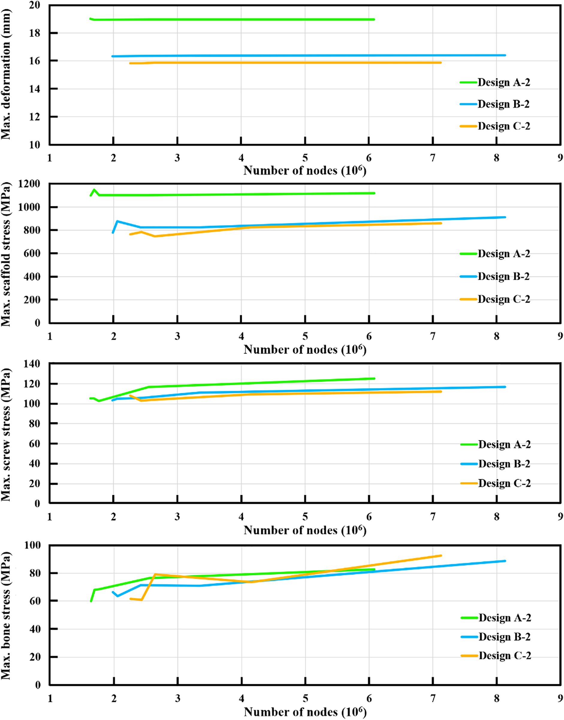
Figure 4: The results of the convergence analysis for the maximum deformation, maximum scaffold stress, maximum screw stress, and maximum bone stress
3.2 Maximum Deformation of the Intact and Treated Femurs
After loading a single-leg stance scenario, the intact femur produced a maximum deformation of 18.5 mm at the proximal femur. This bone deformation result was used as the standard to evaluate the strengths and limitations of the bone defect implants. The maximum deformation of the injured femur treated with various bone defect implants occurred at the proximal femur (Fig. 5). Three different scaffold designs with a pillar diameter of 1.5 mm revealed more considerable maximum deformation than the intact femur. Fortunately, the deformation could be reduced by increasing the pillar diameter for all scaffold structure designs. Thus, Design A-3 revealed the smallest maximum deformation compared to Design A-1 and Design A-2. Similar findings could be found for Design B and Design C (Fig. 5). Based on the same pillar diameter, the maximum deformation of Design C was smaller than that of Design A and Design B. It can be found that Design C has the strongest microstructure compared to Design A and Design B.
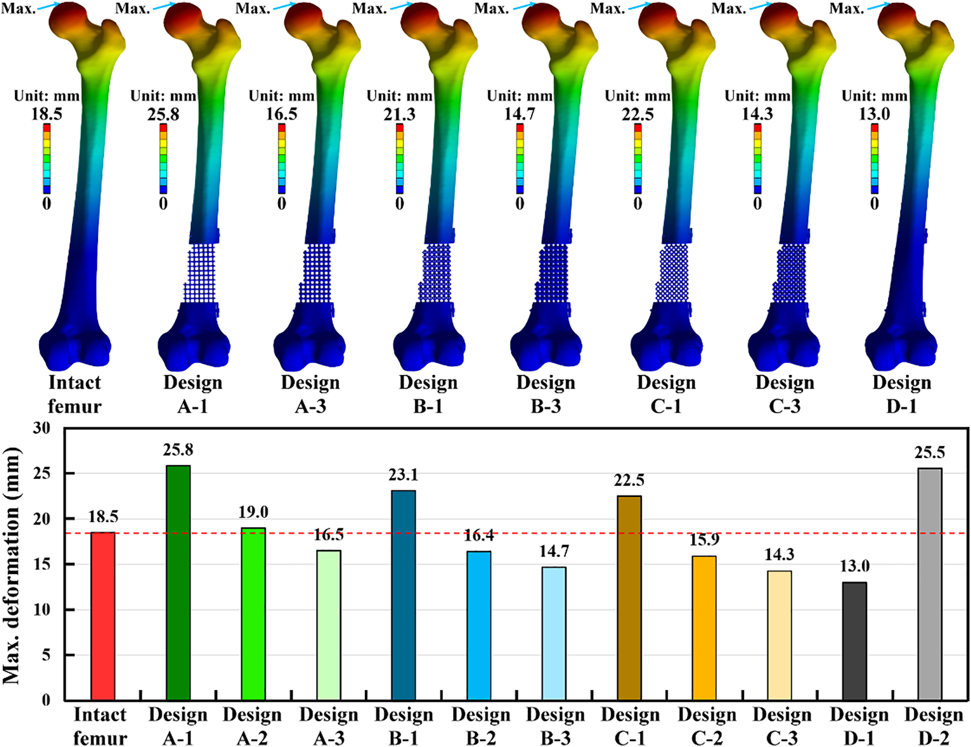
Figure 5: The displacement distribution and the results of the maximum deformation for the intact and treated femur models
Two solid scaffold designs with different materials have varied results on the maximum deformation. Design D-1, made of titanium alloy, revealed the lowest maximum deformation among all treated situations. However, Design D-2, made of PEEK, showed the highest maximum deformation among all treated situations except for Design A-1 (Fig. 5). Compared to the intact femur, Design A-1, Design A-2, Design B-1, Design C-1, and Design D-2 have exceeded the bone deformation standard obtained from the intact femur. Thus, these five scaffold designs were not suggested for treating distal femur bone defects. Design C-3 and D-1 also revealed lower maximum deformation than the intact femur and the other scaffold structure designs. Due to the stress shielding issue, these two scaffold designs were not suggested for treating distal femur bone defects.
3.3 Maximum Stress of the Scaffolds and Screws
The maximum stress of the scaffold-plate structure occurred on the fillet region of pillars at the proximal site of the scaffold for all microstructure scaffold designs. The maximum scaffold stress of three scaffold designs with three pillar diameters was obtained. The scaffold design with a smaller pillar diameter revealed higher maximum scaffold stress. Design A-3, with the largest pillar diameter, showed the lowest scaffold stress compared to Design A-1 and Design A-2. The same findings were found for Design B and Design C. Design D-1 is a solid scaffold design made of titanium alloy. Its maximum stress occurred on the proximal end surface of the scaffold, and it has the lowest maximum scaffold stress among all scaffold designs. Titanium alloy has a yield strength of 880 MPa [27], and this yield stress was used to determine whether the scaffold plate failed. The results showed that only Design A-3, Design B-3, Design C-2, Design C-3, and Design D-1 have lower scaffold stress than the titanium alloy’s yield stress. Design D-2 has the same structure as Design D-1 but was made of PEEK. The maximum scaffold stress of Design D-2 was 50 MPa, which was lower than the PEEK’s yield stress of 80 MPa [33] (Fig. 6).
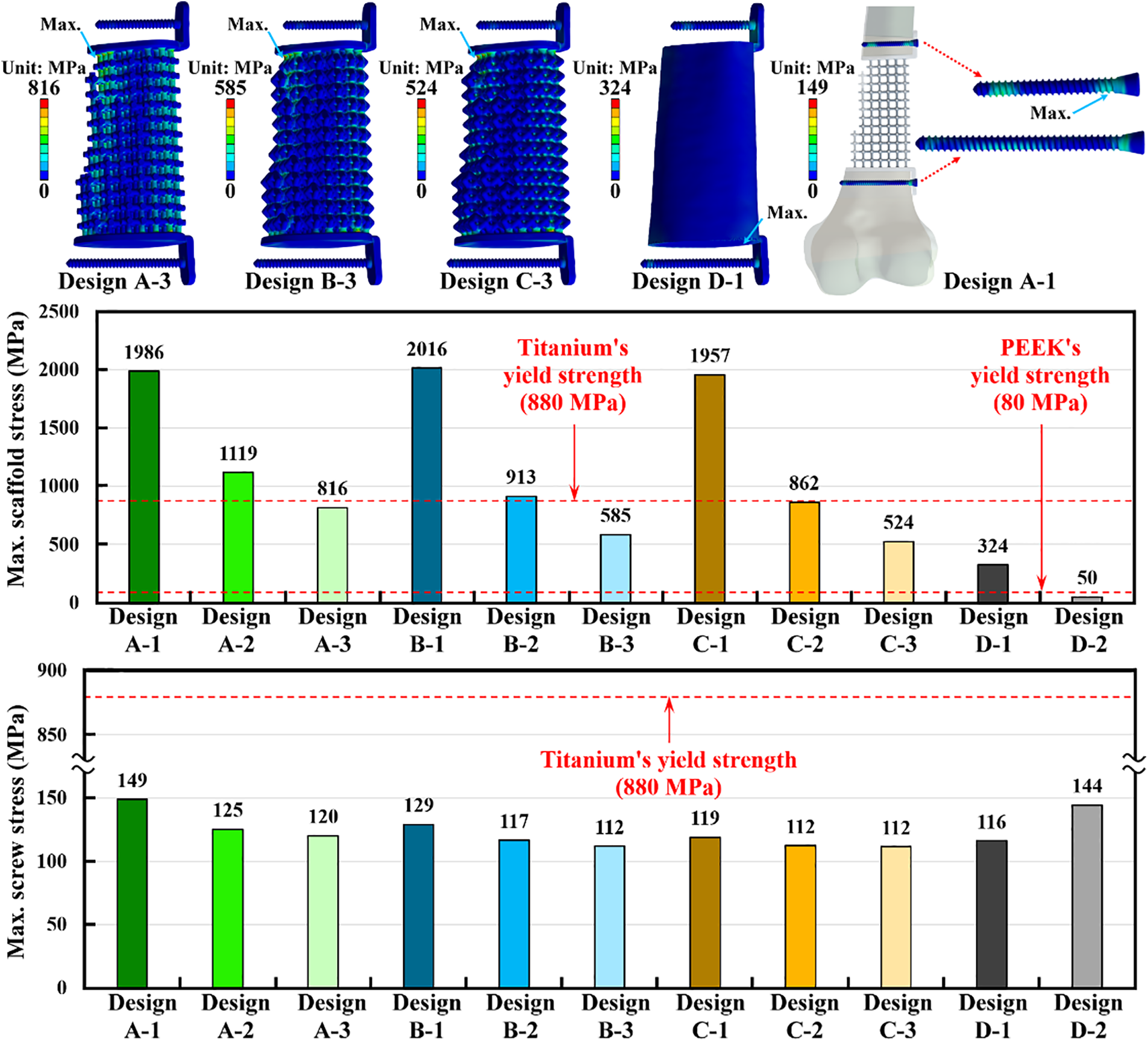
Figure 6: The stress distribution and the results of the maximum implant stress for the scaffold and screws
Except for the scaffold-plate structure, the screw stress was also analyzed. The maximum stress of the screws occurred on the screw thread at the distal site of the proximal screw. The maximum screw stress didn’t significantly change as different scaffold-plate structure designs were used. However, the scaffold-plate constructs with the largest pillar diameter have the lowest maximum screw stress. The solid scaffold design with titanium alloy (Design D-1) has lower screw stress as compared with the solid scaffold design with PEEK (Design D-2). Again, the yield stress of 880 MPa from titanium alloy was also used to determine whether the screws failed or not. The results showed that all titanium scaffold structure designs have screw stress that was significantly lower than the yield stress of the titanium alloy. Additionally, the PEEK scaffold structure design (Design D-2) also revealed the screw stress that was lower than the yield stress of titanium alloy (Fig. 6).
3.4 Maximum Stress of the Intact and Treated Femurs
The bone stress distribution of the intact femur and treated femurs was obtained. The relative high bone stress occurred on the medial and lateral sites near the middle of the intact femur. However, high stress was concentrated at the screw hole for all treated femurs. This stress concentration effect increased the bone stress of the treated femurs. Under the loading of a single-leg stance scenario, the intact femur produced the maximum bone stress of 58 MPa. The maximum bone stress of the injured femur with all scaffold designs was higher than that of the intact femur. The maximum bone stress could be reduced by increasing the pillar diameter for all scaffold structure designs. Thus, Design A-3 revealed the smallest maximum bone stress compared to Design A-1 and Design A-2. Similar findings could be found for Design B and Design C (Fig. 7).
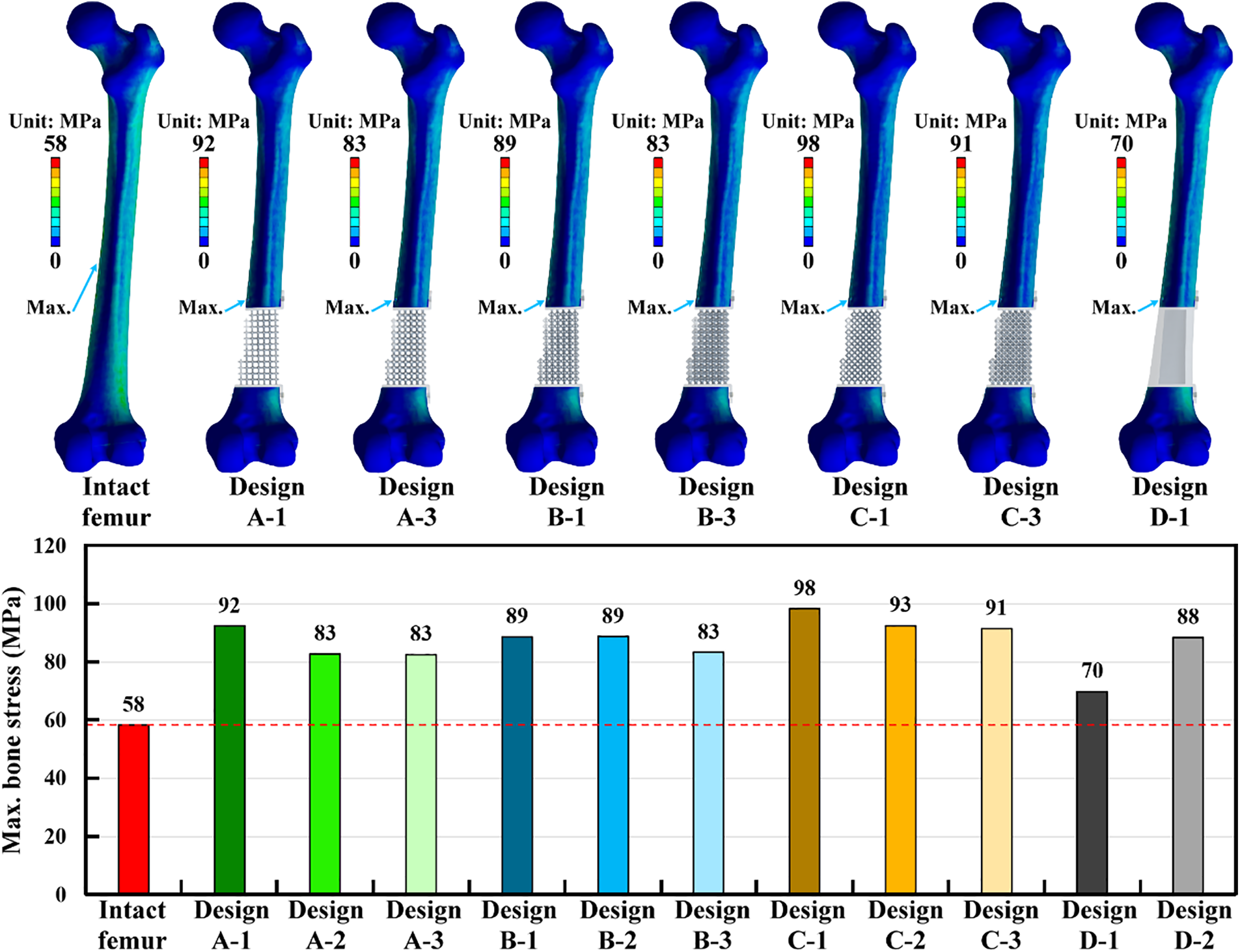
Figure 7: The stress distribution and the results of the maximum bone stress for the intact and treated femur models
Design D-1 was a solid scaffold design made of titanium alloy. This design produced the lowest maximum bone stress among all scaffold structure designs. The solid scaffold design revealed lower stress concentration effects than the microstructure scaffold designs. However, the solid scaffold design with PEEK material (Design D-2) increased the maximum bone stress as compared to the solid scaffold design with titanium alloy material (Design D-1) (Fig. 7).
Bone geometry and bone material distribution are critical parameters for developing a finite element model of the human femur [34,35]. In the present study, both the bone geometry and bone material distribution were developed and considered according to the CT scan images. The bone material was assigned for each femur element using the bone material mapping technique. Young’s modulus of the human femur with average bone mineral density generally ranged from 15 to 17 GPa [36,37]. Thus, the coefficient of 820 in Eq. (4) could be determined. Young’s modulus varied from 584 MPa to 16.1 GPa and could also be calculated according to Eq. (4). The material mapping technique could accurately represent the varied thickness of the cortical shells. It is clearly to be seen that the thickest cortical shell occurred at the femur isthmus, and the thickness gradually decreased in the proximal and distal femur [38]. The thickness of the cortical shells played a significant role in the femur’s deformation or structure stiffness. However, many numerical studies ignored the effects of varied cortical shell thickness and assumed cortical shells to have the ideal constant thickness [28,39]. Although those numerical studies could still investigate their research issues, their conclusions were based on relative predictions, not absolute predictions.
Metal orthopedic implants have been used for many decades to solve bone trauma issues [40,41]. Those metal implants have high structure rigidity and can provide more stable fracture fixation. However, high structure rigidity implies that most of the body weight is taken by metal implants, and the body weight acting on bones is significantly reduced. This changes the stress distribution of bones and causes stress shielding issues [12,42]. The stress shielding issue might deteriorate when metal orthopedic implants have higher structure rigidity. In the present study, the metal solid scaffold design (Design D-1) has the smallest maximum deformation of the femur compared to the metal microstructure scaffold designs. The solid metal scaffold design revealed the maximum femur deformation, which was significantly lower than that of the intact femur. This indicated that the metal solid scaffold design has a higher chance of causing stress shielding problems. The metal microstructure scaffold designs were proposed to reduce the stress shielding problem [16]. However, the pillar diameters of the scaffold designs were a critical factor in affecting the maximum deformation of the femur or the stress shielding effect. The metal microstructure scaffold designs with smaller pillar diameters significantly increased the femur’s maximum deformation and raised the femur’s stress. Non-metal implants are another choice to reduce the stress shielding problem [43]. The present study investigated the maximum deformation of the femur with the PEEK solid scaffold design (Design D-2). The maximum deformation of Design D-2 was significantly higher than that of the solid metal scaffold design and the intact femur. This meant that the PEEK solid scaffold design was not suggested for use in patients with traumatic distal femur defects due to weak implant rigidity.
According to the numerical results obtained by the present study, different scaffold designs revealed different biomechanical outcomes. Selecting a scaffold design that satisfies all the requirements is an important issue. The maximum deformation of the intact femur was used as a standard to investigate the fixation stability and stress shielding. Design A-3, Design B-2, Design B-3, Design C-2, Design D-3, and Design D-1 have lower maximum deformation than the intact femur. This indicated that those scaffold designs can provide enough fixation stability. However, due to its smallest maximum deformation, the solid metal scaffold design (Design D-1) might have a stress shielding problem. The yield strengths of titanium alloy and PEEK were used to judge whether the implants were safe or failed. Design A-3, Design B-3, Design C-2, Design C-3, Design D-1, and Design D-2 revealed the scaffold stresses lower than the material’s yield strength. Thus, those scaffolds had relatively low failure risk. Additionally, all the screws also had lower failure risk because their stresses were significantly lower than the yield strength of titanium alloy. For the femur’s stress, the intact femur revealed a maximum bone stress of 58 MPa. Although all the treated femur models resulted in bone stresses higher than the intact femur, Design A-2, Design A-3, Design B-3, and Design D-1 were closer to the bone stress of the intact femur. Summarizing all the above biomechanical indexes, both Design A-3 and Design B-3 satisfied all the indexes. Design B-3 might be suggested due to the lower scaffold stress than Design A-3.
A hip joint force applied on the femoral head was considered in the present study. The resultant hip joint force is 2873 N. This hip joint force is about four times that of a person with a 75 kg body weight. Past studies have applied this loading to simulate a static single-leg stance condition. It was considered to be the worst-case scenario [44]. According to this loading condition, the scaffold designs with a pillar diameter of 1.5 mm revealed scaffold stresses that were higher than the yield stress of the titanium alloy. This indicated that Design A-1, Design B-1, and Design C-1 have failure issues on the scaffolds under the static single-leg stance loading. To avoid scaffold failure, increasing the pillar diameter of the scaffolds could decrease the maximum scaffold stress and reduce the risk of scaffold failure. The present study also considered the gluteal medius muscle force except for the hip joint force. However, many muscle forces are attached to the human femur and are not considered in the present study. The maximum deformation of the femur, the scaffold stress, the screw stress, and the bone stress might be varied if all the muscle forces on the human femur were considered. Besides, humans must walk, jump, or move on foot daily [45]. These lower-limb activities produced dynamic and repetitive loading on the human feet. This repetitive loading may induce the fatigue failure on the scaffolds, screws, or bones.
There are some potential limitations in this study. Firstly, the patient-specific femur model was developed according to the CT scan images of a single subject. The scaffold designs’ findings might vary as CT scan images from different subjects are used. Secondly, the Hounsfield unit values of the femur obtained from the CT scan images were used to calculate Young’s modulus using the equations proposed by the past study [26]. However, several equations were proposed between the Hounsfield unit values and Young’s modulus of the femur [46]. Besides, the bone material mapping may have a risk of fictitious stress/strain values. Further study on the discussion of the transferred equations is necessary. Third, the hip joint and gluteal medius muscle forces were considered to simulate a static single-leg stance condition. However, the joint and muscle forces on the human femur are dynamic, repetitive, and complicated [47,48]. Further study on the effects of the dynamic loading condition on the scaffold designs is necessary. Fourth, the analysis of stress shielding using deformation might be insufficient. Bone tissue behavior is another important parameter that affects stress-shielding issues. Finally, various bone defect implant designs were evaluated and analyzed based on the intact femur’s loading and boundary conditions. Although a relatively good bone defect design could be found using computational simulation, experimental tests are required to validate the numerical prediction outcomes in the future.
The biomechanical performances for reconstructing a traumatic distal femur defect can be effectively analyzed and discussed using a patient-specific finite element modeling technique. The metal solid scaffold design revealed the most stable fixation but also increased the risk of stress shielding. A microstructure scaffold (Design B-3) can be designed to satisfy all the biomechanical indexes by changing microstructure geometry and pillar diameter. However, this scaffold design suggestion is based on the patient’s bone quality. A three-dimensional finite element model of the femur that considers real bone geometry and bone material distribution can be developed. This patient-specific femur model can be applied to study other femoral injuries. Besides, this patient-specific finite element modeling technique can also be used to create other human or animal bone models.
Acknowledgement: The authors thank the National Taiwan University of Science and Technology and Taipei Medical University for funding this work through the joint research program. The authors also thank the National Library of Medicine for providing computed tomographic scan image data.
Funding Statement: This research was funded by the Taipei Medical University-National Taiwan University of Science and Technology joint research program under Grant No. TMU-NTUST-109-09.
Author Contributions: The authors confirm their contribution to the paper: study conception and design: Hsien-Tsung Lu, Ching-Chi Hsu; data collection: Ching-Chi Hsu, Qi-Quan Jian, Wei-Ting Chen; analysis and interpretation of results: Hsien-Tsung Lu, Ching-Chi Hsu, Qi-Quan Jian, Wei-Ting Chen; draft manuscript preparation: Ching-Chi Hsu. All authors reviewed the results and approved the final version of the manuscript.
Availability of Data and Materials: The data that support the findings of this study are openly available at https://datadiscovery.nlm.nih.gov/Images/Visible-Human-Project/ux2j-9i9a/about_data (accessed on 25 October 2024).
Ethics Approval: The public computed tomographic scan image data of the human male right femur used in the present study are obtained from the National Institutes of Health’s (NIH, United States of America) Visible Human Project. No ethical approval is needed for this study.
Conflicts of Interest: The authors declare no conflicts of interest to report regarding the present study.
References
1. Sokol VK, Kolesnichenko VA, Grygorian E. Characteristics of lower limb injuries in non-fatal road traffic accidents: a retrospective analysis of forensic medical examinations. J Educ Health Sport. 2020;10(12):40–6. doi:10.12775/JEHS.2020.10.12.004. [Google Scholar] [CrossRef]
2. Seid M, Azazh A, Enquselassie F, Yisma E. Injury characteristics and outcome of road traffic accident among victims at Adult Emergency Department of Tikur Anbessa specialized hospital, Addis Ababa, Ethiopia: a prospective hospital based study. BMC Emerg Med. 2015;15:1–9. doi:10.1186/s12873-015-0035-4. [Google Scholar] [PubMed] [CrossRef]
3. Roumeliotis L, Kanakaris NK, Nikolaou VS, Danias N, Konstantoudakis G, Papadopoulos IN. Femoral fractures are an indicator of increased severity of injury for road traffic collision victims: an autopsy-based case-control study on 4895 fatalities. Arch Orthop Trauma Surg. 2022;142(10):2645–58. doi:10.1007/s00402-021-03997-8. [Google Scholar] [PubMed] [CrossRef]
4. Luthfi APWY, Hendarji A, Dalitan IM, Wedhanto S. Primary dynamic interlocking nail in femoral shaft fracture: a case series. Int J Surg Case Rep. 2023;105:108051. doi:10.1016/j.ijscr.2023.108051. [Google Scholar] [PubMed] [CrossRef]
5. Ulusoy I, Kivrak A, Yilmaz E. Evaluation of the results of the proximal femoral nail surgery for intertrochanteric femur fractures. Medicine. 2022;11(2):750–6. [Google Scholar]
6. Sarukte V, Rai AK, Shrinivas L, Pandurang DAKS, Bansal D. Functional outcome following fixation of diaphyseal fracture of femur with closed intramedullary interlocking nail in adults: a prospective study. Int J Orthop. 2022;8(2):202–5. doi:10.22271/ortho. [Google Scholar] [CrossRef]
7. Fan S, Yin M, Xu Y, Ren C, Ma T, Lu Y, et al. Locking compression plate fixation of femoral intertrochanteric fractures in patients with preexisting proximal femoral deformity: a retrospective study. J Orthop Surg Res. 2021;16(1):1–8. [Google Scholar]
8. Lee WT, Murphy D, Kagda FH, Thambiah J. Proximal femoral locking compression plate for proximal femoral fractures. J Orthop Surg. 2014;22(3):287–93. doi:10.1177/230949901402200304. [Google Scholar] [PubMed] [CrossRef]
9. Kiyono M, Noda T, Nagano H, Maehara T, Yamakawa Y, Mochizuki Y, et al. Clinical outcomes of treatment with locking compression plates for distal femoral fractures in a retrospective cohort. J Orthop Surg Res. 2019;14:1–9. [Google Scholar]
10. Corona PS, Altayó M, Amat C, Vicente M, Velez R. Reconstruction of infected post-traumatic bone defects of the distal femur with the CompressⓇ implant. Preliminary results of a staged non-biological strategy. Injury. 2021;52(3):606–15. doi:10.1016/j.injury.2020.10.016. [Google Scholar] [PubMed] [CrossRef]
11. Qu H. Additive manufacturing for bone tissue engineering scaffolds. Mater Today Commun. 2020;24:101024. doi:10.1016/j.mtcomm.2020.101024. [Google Scholar] [CrossRef]
12. Savio D, Bagno A. When the total hip replacement fails: a review on the stress-shielding effect. Processes. 2022;10:612. doi:10.3390/pr10030612. [Google Scholar] [CrossRef]
13. Nomura J, Takezawa A, Zhang H, Kitamura M. Design optimization of functionally graded lattice infill total hip arthroplasty stem for stress shielding reduction. Proc Inst Mech Eng H. 2022;236(4):515–25. doi:10.1177/09544119221075140. [Google Scholar] [PubMed] [CrossRef]
14. Naghavi SA, Lin C, Sun C, Tamaddon M, Basiouny M, Garcia-Souto P, et al. Stress shielding and bone resorption of press-fit polyether-ether-ketone (PEEK) hip prosthesis: a sawbone model study. Polymers. 2022;14(21):4600. doi:10.3390/polym14214600. [Google Scholar] [PubMed] [CrossRef]
15. Charbonnier B, Hadida M, Marchat D. Additive manufacturing pertaining to bone: hopes, reality and future challenges for clinical applications. Acta Biomater. 2021;121:1–28. doi:10.1016/j.actbio.2020.11.039. [Google Scholar] [PubMed] [CrossRef]
16. Wojnicz W, Augustyniak M, Borzyszkowski P. Mathematical approach to design 3D scaffolds for the 3D printable bone implant. Biocybern Biomed Eng. 2021;41(2):667–78. doi:10.1016/j.bbe.2021.05.001. [Google Scholar] [CrossRef]
17. Wang L, Kang J, Sun C, Li D, Cao Y, Jin Z. Mapping porous microstructures to yield desired mechanical properties for application in 3D printed bone scaffolds and orthopaedic implants. Mater Des. 2017;133:62–8. doi:10.1016/j.matdes.2017.07.021. [Google Scholar] [CrossRef]
18. Ghouse S, Reznikov N, Boughton OR, Babu S, Ng KG, Blunn G, et al. The design and in vivo testing of a locally stiffness-matched porous scaffold. Appl Mater Today. 2019;15:377–88. doi:10.1016/j.apmt.2019.02.017. [Google Scholar] [PubMed] [CrossRef]
19. Yee-Yanagishita C, Fogel G, Douglas B, Essayan G, Poojary B, Martin N, et al. Biomechanical comparison of subsidence performance among three modern porous lateral cage designs. Clin Biomech. 2022;99:105764. doi:10.1016/j.clinbiomech.2022.105764. [Google Scholar] [PubMed] [CrossRef]
20. Zhang B, Pei X, Zhou C, Fan Y, Jiang Q, Ronca A, et al. The biomimetic design and 3D printing of customized mechanical properties porous Ti6Al4V scaffold for load-bearing bone reconstruction. Mater Des. 2018;152:30–9. doi:10.1016/j.matdes.2018.04.065. [Google Scholar] [CrossRef]
21. Zhang W, Sun C, Zhu J, Zhang W, Leng H, Song C. 3D printed porous titanium cages filled with simvastatin hydrogel promotes bone ingrowth and spinal fusion in rhesus macaques. Biomater Sci. 2020;8(15):4147–56. doi:10.1039/D0BM00361A. [Google Scholar] [PubMed] [CrossRef]
22. Zeng W, Liu Y, Hou X. Biomechanical evaluation of internal fixation implants for femoral neck fractures: a comparative finite element analysis. Comput Methods Programs Biomed. 2020;196:105714. doi:10.1016/j.cmpb.2020.105714. [Google Scholar] [PubMed] [CrossRef]
23. Zhong Z, Lan X, Xiang Z, Duan X. Femoral neck system and cannulated compression screws in the treatment of non-anatomical reduction Pauwels type-III femoral neck fractures: a finite element analysis. Clin Biomech. 2023;108:106060. doi:10.1016/j.clinbiomech.2023.106060. [Google Scholar] [PubMed] [CrossRef]
24. Yang AL, Mao W, Chang SM, He YQ, Li LL, Li HL, et al. Computational evaluation of the axis-blade angle for measurements of implant positions in trochanteric hip fractures: a finite element analysis. Comput Biol Med. 2023;158:106830. doi:10.1016/j.compbiomed.2023.106830. [Google Scholar] [PubMed] [CrossRef]
25. Schermann H, Gortzak Y, Kollender Y, Dadia S, Trabelsi N, Yosibash Z, et al. Patient-specific computed tomography-based finite element analysis: a new tool to assess fracture risk in benign bone lesions of the femur. Clin Biomech. 2020;80:105155. doi:10.1016/j.clinbiomech.2020.105155. [Google Scholar] [PubMed] [CrossRef]
26. Li X, Viceconti M, Cohen MC, Reilly GC, Carré MJ, Offiah AC. Developing CT based computational models of pediatric femurs. J Biomech. 2015;48(10):2034–40. doi:10.1016/j.jbiomech.2015.03.027. [Google Scholar] [PubMed] [CrossRef]
27. de Melo EJMJr, Francischone CE. Three-dimensional finite element analysis of two angled narrow-diameter implant designs for an all-on-4 prosthesis. J Prosthet Dent. 2020;124(4):477–84. doi:10.1016/j.prosdent.2019.09.015. [Google Scholar] [PubMed] [CrossRef]
28. Shih KS, Hsu CC, Hsu TP, Hou SM, Liaw CK. Biomechanical analyses of static and dynamic fixation techniques of retrograde interlocking femoral nailing using nonlinear finite element methods. Comput Methods Programs Biomed. 2014;113(2):456–64. doi:10.1016/j.cmpb.2013.11.002. [Google Scholar] [PubMed] [CrossRef]
29. Stolk J, Verdonschot N, Huiskes R. Hip-joint and abductor-muscle forces adequately represent in vivo loading of a cemented total hip reconstruction. J Biomech. 2001;34(7):917–26. doi:10.1016/S0021-9290(00)00225-6. [Google Scholar] [PubMed] [CrossRef]
30. Wang CJ, Yettram AL, Yao MS, Procter P. Finite element analysis of a Gamma nail within a fractured femur. Med Eng Phys. 1998;20(9):677–83. doi:10.1016/S1350-4533(98)00079-4. [Google Scholar] [PubMed] [CrossRef]
31. Ruiz-de-Galarreta S, Jeffers J, Ghouse S. A validated finite element analysis procedure for porous structures. Mater Des. 2020;189:108546. doi:10.1016/j.matdes.2020.108546. [Google Scholar] [CrossRef]
32. Wang JP, Guo D, Wang SH, Yang YQ, Li G. Structural stability of a polyetheretherketone femoral component—A 3D finite element simulation. Clin Biomech. 2019;70:153–7. doi:10.1016/j.clinbiomech.2019.09.001. [Google Scholar] [PubMed] [CrossRef]
33. Najeeb S, Zafar MS, Khurshid Z, Siddiqui F. Applications of polyetheretherketone (PEEK) in oral implantology and prosthodontics. J Prosthodont Res. 2016;60(1):12–9. doi:10.1016/j.jpor.2015.10.001. [Google Scholar] [PubMed] [CrossRef]
34. Mishra RN, Singh MK, Kumar V. Biomechanical analysis of human femur using finite element method: a review study. Mater Today Proc. 2022;56:384–9. doi:10.1016/j.matpr.2022.01.222. [Google Scholar] [CrossRef]
35. Schileo E, Pitocchi J, Falcinelli C, Taddei F. Cortical bone mapping improves finite element strain prediction accuracy at the proximal femur. Bone. 2020;136:115348. doi:10.1016/j.bone.2020.115348. [Google Scholar] [PubMed] [CrossRef]
36. Li H, Yao B, Li Z, Peng Y, Fan H. Compressive properties and deformation mechanism of selective laser melting of Ti6Al4V porous femoral implants based on topological optimization. Compos Struct. 2023;321:117326. doi:10.1016/j.compstruct.2023.117326. [Google Scholar] [CrossRef]
37. Mobasseri S, Karami B, Sadeghi M, Tounsi A. Bending and torsional rigidities of defected femur bone using finite element method. Biomed Eng Advs. 2022;3:100028. doi:10.1016/j.bea.2022.100028. [Google Scholar] [CrossRef]
38. Someya K, Mochizuki T, Hokari S, Tanifuji O, Katsumi R, Koga H, et al. Age-and sex-related characteristics in cortical thickness of femoral diaphysis for young and elderly subjects. J Bone Miner Metab. 2020;38(4):533–43. doi:10.1007/s00774-019-01079-9. [Google Scholar] [PubMed] [CrossRef]
39. Huang L, Chen F, Wang S, Wei Y, Huang G, Chen J, et al. Three-dimensional finite element analysis of silk protein rod implantation after core decompression for osteonecrosis of the femoral head. BMC Musculoskelet Disord. 2019;20(1):1–10. doi:10.1186/s12891-018-2378-y. [Google Scholar] [CrossRef]
40. Shah MD, Kapoor CS, Soni RJ, Patwa JJ, Golwala PP. Evaluation of outcome of proximal femur locking compression plate (PFLCP) in unstable proximal femur fractures. J Clin Orthop Trauma. 2017;8(4):308–12. doi:10.1016/j.jcot.2016.11.005. [Google Scholar] [PubMed] [CrossRef]
41. Chandra G, Pandey A. Biodegradable bone implants in orthopedic applications: a review. Biocybern Biomed Eng. 2020;40(2):596–610. doi:10.1016/j.bbe.2020.02.003. [Google Scholar] [CrossRef]
42. Ceddia M, Trentadue B, De Giosa G, Solarino G. Topology optimization of a femoral stem in titanium and carbon to reduce stress shielding with the FEM method. J Compos Sci. 2023;7(7):298. doi:10.3390/jcs7070298. [Google Scholar] [CrossRef]
43. de Ruiter L, Rankin K, Browne M, Briscoe A, Janssen D, Verdonschot N. Decreased stress shielding with a PEEK femoral total knee prosthesis measured in validated computational models. J Biomech. 2021;118:110270. doi:10.1016/j.jbiomech.2021.110270. [Google Scholar] [PubMed] [CrossRef]
44. Duda GN, Schneider E, Chao EY. Internal forces and moments in the femur during walking. J Biomech. 1997;30(9):933–41. doi:10.1016/S0021-9290(97)00057-2. [Google Scholar] [PubMed] [CrossRef]
45. Hamza MF, Ghazilla RAR, Muhammad BB, Yap HJ. Balance and stability issues in lower extremity exoskeletons: a systematic review. Biocybern Biomed Eng. 2020;40(4):1666–79. doi:10.1016/j.bbe.2020.09.004. [Google Scholar] [CrossRef]
46. Helgason B, Perilli E, Schileo E, Taddei F, Brynjólfsson S, Viceconti M. Mathematical relationships between bone density and mechanical properties: a literature review. Clin Biomech. 2008;23(2):135–46. doi:10.1016/j.clinbiomech.2007.08.024. [Google Scholar] [PubMed] [CrossRef]
47. Kersh ME, Martelli S, Zebaze R, Seeman E, Pandy MG. Mechanical loading of the femoral neck in human locomotion. J Bone Miner Res. 2018;33(11):1999–2006. doi:10.1002/jbmr.3529. [Google Scholar] [PubMed] [CrossRef]
48. Chun BJ, Jang IG. Determination of the representative static loads for cyclically repeated dynamic loads: a case study of bone remodeling simulation with gait loads. Comput Methods Programs Biomed. 2021;200(12):105924. doi:10.1016/j.cmpb.2020.105924. [Google Scholar] [PubMed] [CrossRef]
Cite This Article
 Copyright © 2025 The Author(s). Published by Tech Science Press.
This work is licensed under a Creative Commons Attribution 4.0 International License , which permits unrestricted use, distribution, and reproduction in any medium, provided the original work is properly cited.
 Downloads
 Citation Tools