 Open Access
ARTICLE
Performance Analysis of Curved Track G2T-FSO (Ground-to-Train Free Space Optical) Model under Various Weather Conditions
1 Department of Electrical Engineering, University of Tabuk, Tabuk, 71491, Saudi Arabia
2 Faculty of Electrical and Electronic Engineering, Universiti Tun Hussein Onn Malaysia (UTHM), Johor, 86400, Malaysia
3 Center for Communication Systems and Sensing, King Fahd University of Petroleum and Minerals (KFUPM), Dhahran, 31261, Saudi Arabia
4 Department of Mechanical Engineering, University of Tabuk, Tabuk, 71491, Saudi Arabia
* Corresponding Author: Mohammed A. Alhartomi. Email:
Computer Modeling in Engineering & Sciences 2024, 141(3), 2087-2105. https://doi.org/10.32604/cmes.2024.055679
Received 04 July 2024; Accepted 03 September 2024; Issue published 31 October 2024
Abstract
The demand for broadband data services on high-speed trains is rapidly growing as more people commute between their homes and workplaces. However, current radio frequency (RF) technology cannot adequately meet this demand. In order to address the bandwidth constraint, a technique known as free space optics (FSO) has been proposed. This paper presents a mathematical derivation and formulation of curve track G2T-FSO (Ground-to-train Free Space Optical) model, where the track radius characteristics is 2667 m, divergence angle track is 1.5° for train velocity at V = 250 km/h. Multiple transmitter configurations are proposed to maximize coverage range and enhance curve track G2T-FSO link performance under varying weather conditions. The curved track G2T-FSO model was evaluated in terms of received power, signal-to-noise ratio (SNR), bit error rate (BER), and eye diagrams. The results showed maximum coverage lengths of 618, 505, 365, and 240 m for 4Tx/1Rx, 3Tx/1Rx, 2Tx/1Rx, and 1Tx/1Rx configurations, respectively. The analyzed results demonstrate that the G2T-FSO link can be effectively implemented under various weather conditions.Keywords
With high-speed trains (HSTs) around the globe traveling at speeds over 250 km/h, they are increasingly favored for long-distance journeys. As the popularity of high-speed public transport and internet-connected devices grows, there is a rising demand for fast and reliable onboard internet. Current technologies, such as IEEE 802.11 p and Long-Term Evolution (LTE), can only meet certain requirements, especially at higher train speeds [1]. Even advanced radio frequency (RF) solutions, which theoretically offer speeds of 54/75 Mbps, often drop below 10 Mbps in real-world usage [2]. Free space optical (FSO) communication, also known as open-air photonics infrared broadband, uses light to transmit data through free space, including air, outer space, and vacuum. Operating in the 780–1600 nm range, FSO achieves high data rates over distances from a few meters to a thousand kilometers, with applications in deep-space communications, unmanned vehicles, and ultra-high-speed trains. For high-speed trains exceeding 250 km/h, traditional RF technologies struggle to meet data demands due to challenges like the Doppler effect and frequent handovers [3,4]. The growing demand for swift connectivity on trains has boosted interest in ground-to-train (G2T) communication. The authors in [5,6] conducted an exploratory study on the feasibility of FSO systems in this context. Their findings revealed encouraging data transfer speeds, although the dynamics of a moving train introduced certain challenges. Authors in [1] introduced free-space optics technique for high-speed train communication that reduces the required number of base stations from 113 to fewer than 10 while achieving a fixed data rate of 1.25 Gbps, addressing limitations in existing technologies and accounting for various weather conditions. In [7], three wavelengths (850, 1330, and 1550 nm) in a dual-wavelength free-space optics model for high-speed train communication at a bit rate of 10 Gb/s.
There are various G2T-FSO models using numerical simulations that have been carried out utilizing various track geometry models and FSO performance evaluations. Paudel et al. [8] developed numerous models for G2T-FSO communication. The author developed a straight-track model based on a Lambertian model, with a light emitting diode (LED) assumed to establish the link. The geometrical models’ analysis obtained a 20 m range distance at 1 Gbps data rates. In addition, a curved track model with various geometrical features was developed in another work [9]. The expected turbulent loss, it provided coverage of 50 m at 100 Mbs and 154 m at 10 Mbps. It showed a limited track radius range of 120–500 m, which does not allow for high-speed trains to operate on curves. Additionally, Reference [10] obtained data rates of 50 Mbps at link distances of 75 m using a Gaussian source model that leverages a laser diode for higher transmitted power. Several studies investigated the G2T-FSO straight-track concept, which obtained a variety of link ranges at varying data rates. Reference [11] obtained a coverage distance of 180 m at a high data rate of 5 Gbps, while Reference [3] optimized a model with two transceivers to attain 509 m coverage at 1 Gbps. Also, another model improved link performance to increase the 75 m range to 99 m at 1 Gbps [12]. Previous research investigated link coverage range, transceiver design, track configuration, bit error rate (BER), data rates, handover, number of base stations, and weather attenuation effects. Despite past work, current research frequently emphasizes straight-track configurations and the influence of a few parameters on FSO channel losses. Therefore, there is no adequate combination of weather attenuation effects, railway configuration, and FSO link configurations. Many attempts were made to extend coverage lengths; however, except in [5], it used a single-track FSO link with low data rate considerations. Mabrouk et al. [13] investigated the geometric loss in curved track G2T-FSO link and evaluated the impact of varying both vertical and horizontal distances. However, there is a shortage of comprehensive performance evaluation and performance improvement initiatives for curved track models.
Due to these shortcomings, further research was needed on G2T-FSO models, including multiple track geometries, performance enhancement, multiple base station (BS) transmitters, and weather conditions. This paper described the implementation of G2T-FSO communication links, utilizing the concept of multiple transmitters to achieve high-performance links with extended coverage ranges and improved data rates. It introduced new curved track G2T-FSO mathematical link model, accounting for driving speeds of up to 250 km/h, specifically considering high-speed train scenarios, which resulted in enhanced link performance. The evaluation of G2T-FSO link performance was characterized across various weather conditions, including clear, rainy, and foggy conditions, employing the NRZ modulation technique. The main contributions of this paper were as follows:
• Derive a mathematical model for a curved track with clearance distance, FSO link, Cant excess, Cant deficit, and maximum radius. These values were chosen based on the train’s physical characteristics and the maximum permitted speeds on a curve.
• To Enhance G2T-FSO performance and expand link coverage ranges, we adopted the multi-transmitter concept and evaluated and depicted system performance in terms of received power, signal-to-noise ratio (SNR), BER, and eye diagram.
This paper is organized as follows: Section 2 presents the system model for curved track G2T-FSO communication, including the mathematical derivations. Section 3 provides the results, discussions, and performance evaluation of the G2T-FSO communication link. Finally, the paper concludes in Section 4.
2.1 Train Physical Behavior and Curved Track Alignment
This section discusses the factors influencing the position of a train on a curved railway, crucial for determining the appropriate track radius in developing the curved track G2T-FSO link model. Since the advent of railways in 1825, the basic systems for straight and curved track navigation have remained consistent. Unlike other vehicles, trains are guided by their wheelsets along the track without active steering by a driver [14]. On curved tracks, centrifugal forces cause the train to tilt. Key parameters include the cant angle (δ-Cant), track cant (U), and track gauge (G), as shown in Fig. 1. Residual lateral acceleration (ζ) is measured in m/s² or g, while cant excess (E) and cant deficiency (I) are measured in millimeters.
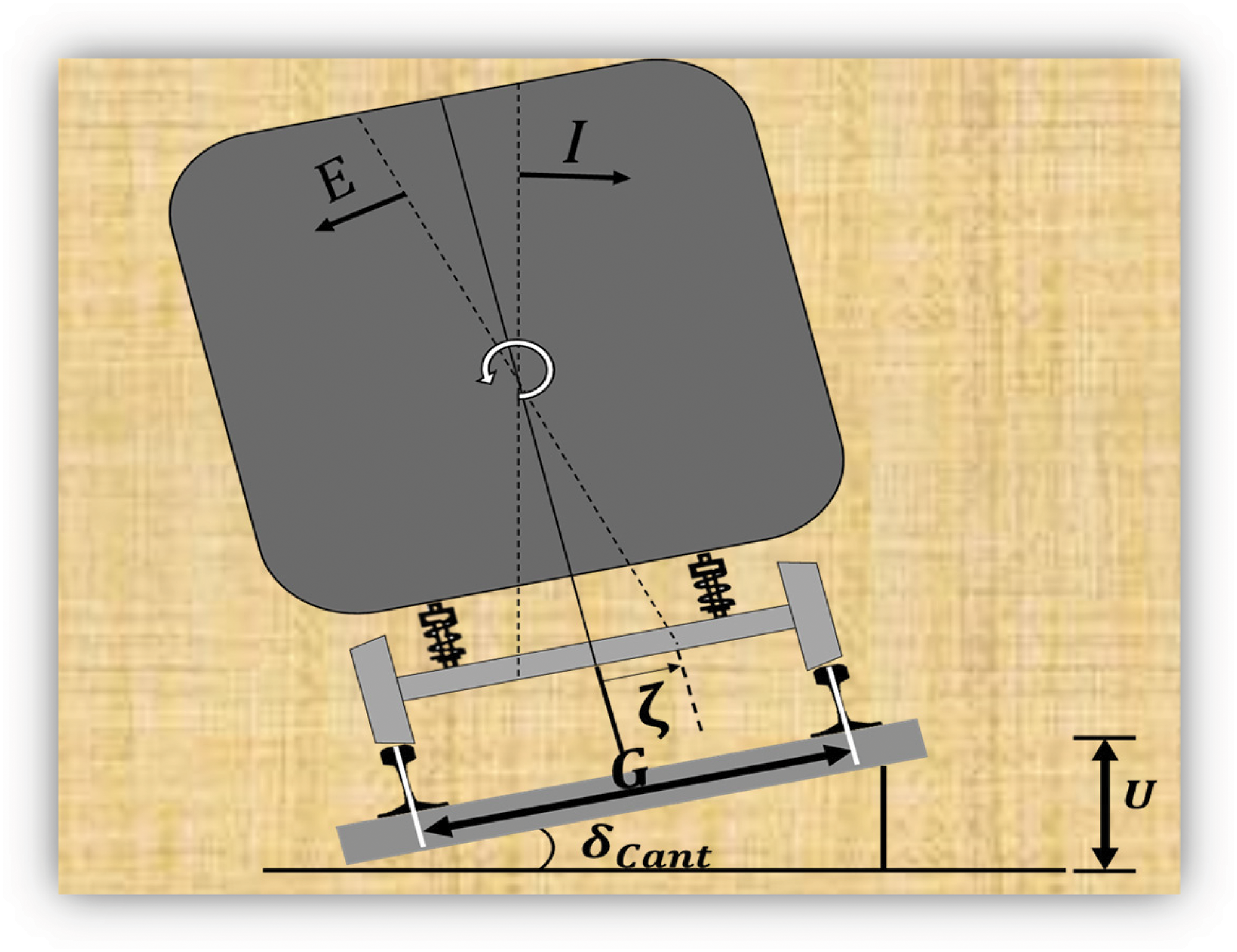
Figure 1: Position of the train in a curved track section
In railway engineering, proper distribution of train load on wheelsets is essential, particularly on curved tracks with a specific cant (or superelevation). This design helps reduce wear and tear between the rails and rolling stock, counteracting the effects of lateral forces [15]. These measures ensure passenger comfort and prevent derailment by minimizing the risk of wheel slippage [16]. Additionally, trains must maintain an equilibrium speed when negotiating curves to balance train load forces and radial acceleration, keeping them perpendicular to the track plane. Cant helps counteract centrifugal forces at this equilibrium speed, ensuring stability and smooth operation [16].
Cant deficiency occurs when the train’s speed exceeds the equilibrium speed, causing it to tilt towards the outer rail of the curve. Conversely, if the speed is lower than the equilibrium speed, cant deficiency causes the train to tilt towards the inner rail. To calculate the maximum permissible speed for a curve in this paper, parameters such as track cant length, cant excess, cant deficiency, and track radius must be considered. Fig. 2 illustrates the track curvature for a single wheelset, with V representing the train’s speed along the curve [17].
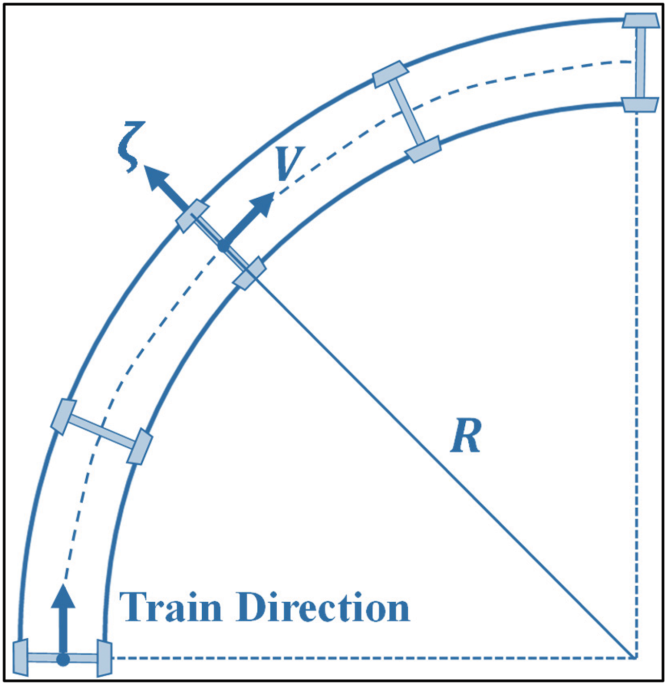
Figure 2: Track curvature for the motion of a single wheelset
2.2 Curved Track G2T-FSO Model with Considerations for Horizontal Alignment Radii
Fig. 3 illustrates a curved track with G2T-FSO communication, where the link connects to ground base stations (BSs) along the railway. Multiple FSO transceivers on the train’s roof enable line of sight (LOS) communication with the BSs. ZC1 is the propagation distance between the FSO transceiver and the BS, while
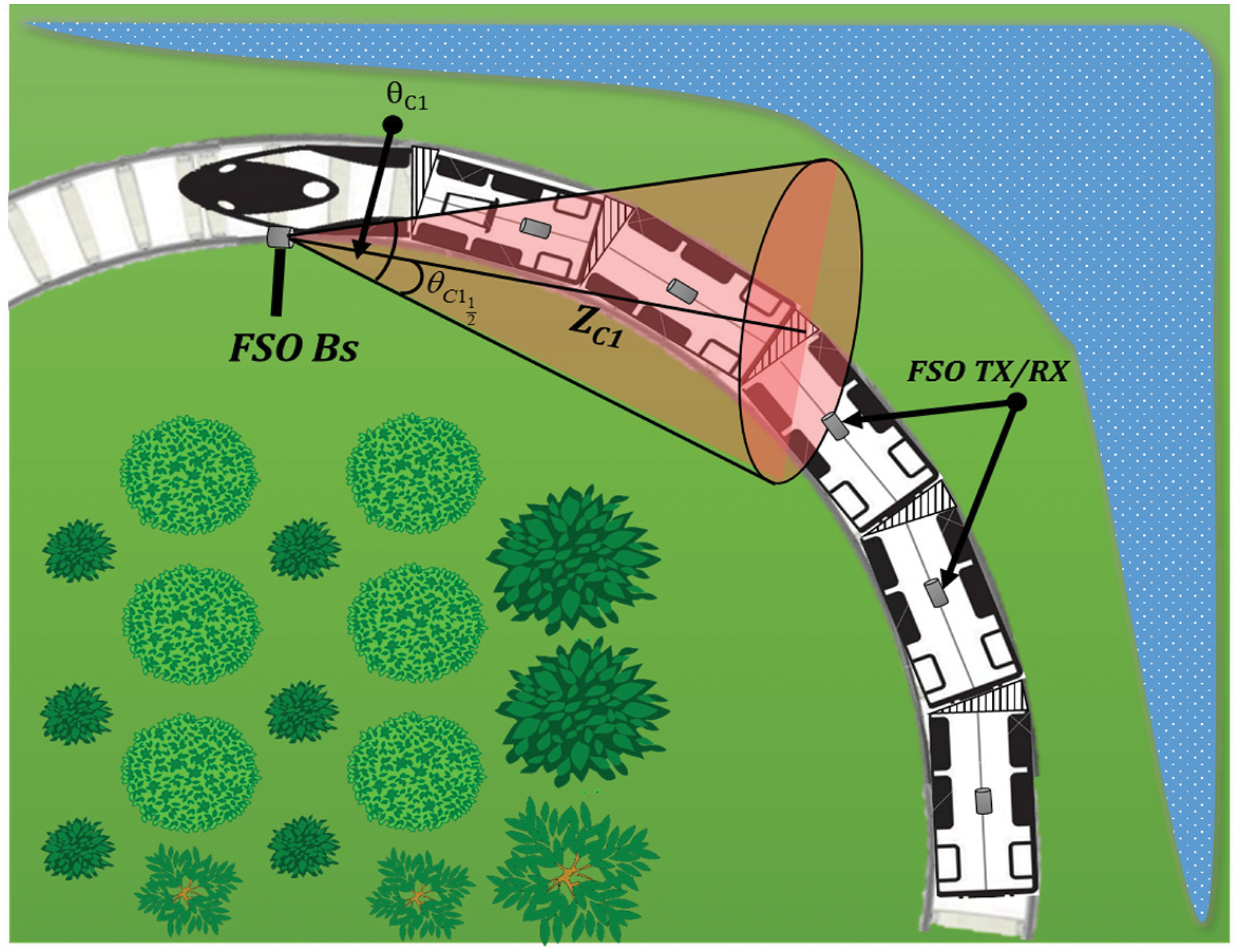
Figure 3: Proposed G2T-FSO model for curved track
The focus of this paper is on high-speed trains. They have no clear definition but are often recognized by driving speeds above 200 km/h [17,18]. Thus, the theoretical required horizontal radii to obtain high speeds might be determined by considering the physical behavior of trains over a curve. This can be achieved by considering the train’s geometrical behavior in terms of maximum track deficiency as well as its physical behavior in terms of maximum permitted speeds along a horizontal alignment [19,20]. Assuming a speed of 250 km/h, the minimum required track radius to achieve this case might be approximated as [17]:
where
where
Fig. 4 illustrates the geometrical attributes of the G2T-FSO curved track on x and y axes. RC denotes the track radius, and
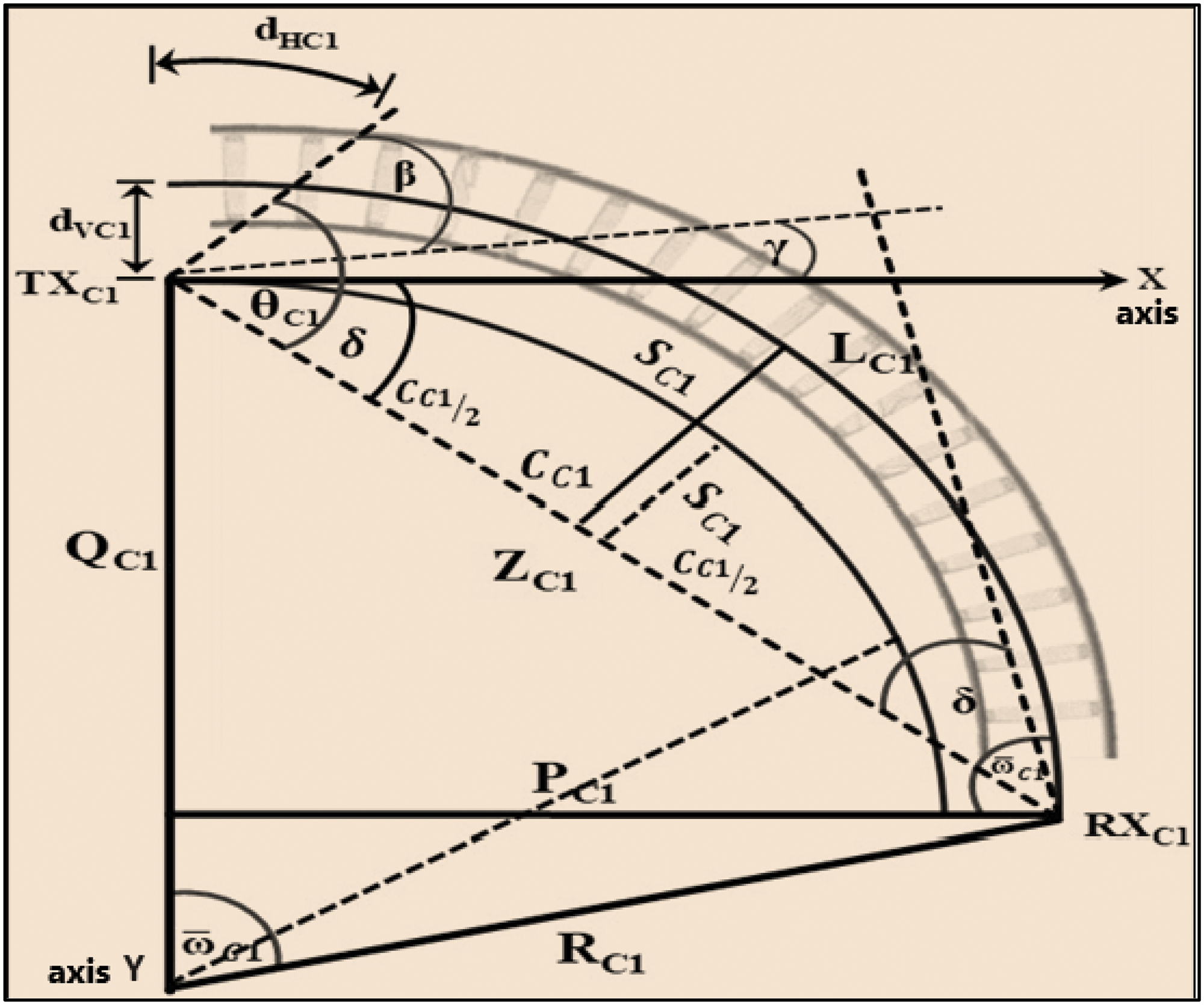
Figure 4: Geometrical properties and LOS considerations of curved track G2T-FSO link
The parameter δ represents the coverage angle along the propagation distance
According to Fig. 4, the angle between
where
The angle between the beam edge and x-axis is δ, which is defined as:
Given QC1 y-axis coordinate, PC1 x-axis coordinate might be defined as:
Using Pythagorean theorem
which indicates that,
Assuming the curved track divergence angle,
Given that,
Further, the receiver’s irradiance angle is:
Therefore, the divergence angle for the first curved track
However, the propagation length is formulated as:
In an FSO link with a clear LOS, side clearance is needed. Referring to Fig. 3 for clearances beside the curved track, where
and since
Thus, the length of CC1 of arch within radius RC1 is defined as:
As shown in Fig. 3, Sagitta
Considering a non-diffraction limited geometrical loss, which is a function of divergence angle
where dR is the receiver aperture diameter, dT is the transmitter aperture diameter, Z is the LOS range in km, and LG (dB) represents the specific geometrical loss in disciples.
Referring to Eq. (18), and substituting Eqs. (7) and (8) into (18) geometrical loss at curve track is defined as:
The optical received power of a single FSO transmitter is typically defined as [25]:
2.5 Receiver Performance Evaluation
The received power at the receiver for a single transmitter depends on the lens aperture diameter
The photodetector converts the optical signal to an electrical signal. During detection, the signal faces various noise sources: shot noise
where
Furthermore, the factor (
It accounts for the noise power variance when detecting 1 and 0 bits. Another key parameter is the link margin, which evaluates the link’s ability to compensate for scintillation, scattering, and absorption losses. The link margin is defined by [33]:
Total transmitted power
where acceptable link range is governed by an error-free FSO link with BER of 10−9. Eq. (6) is used for 1 km rail track and Eq. (7) for a 10 km rail track.
FSO link establishes an optical link using the earth’s atmosphere. This limits beam transmission due to photon absorption and scattering. Fog and rain attenuation levels were assessed using meteorological data and empirical models. Rain and fog attenuations were categorized by ITU-R code to characterize FSO channel [34]. Table 1 presents the link power budget for the curved track FSO-G2T communication link used in this simulation, with a wavelength of 1550 nm and a data rate of 2.5 Gbps.

The G2T-FSO communication system, shown in Fig. 5, was modeled in OptiSystem with a 4Tx-1Rx configuration. It uses multiple lasers connected to a single OOK modulator to produce multiple beams that propagate along the link.
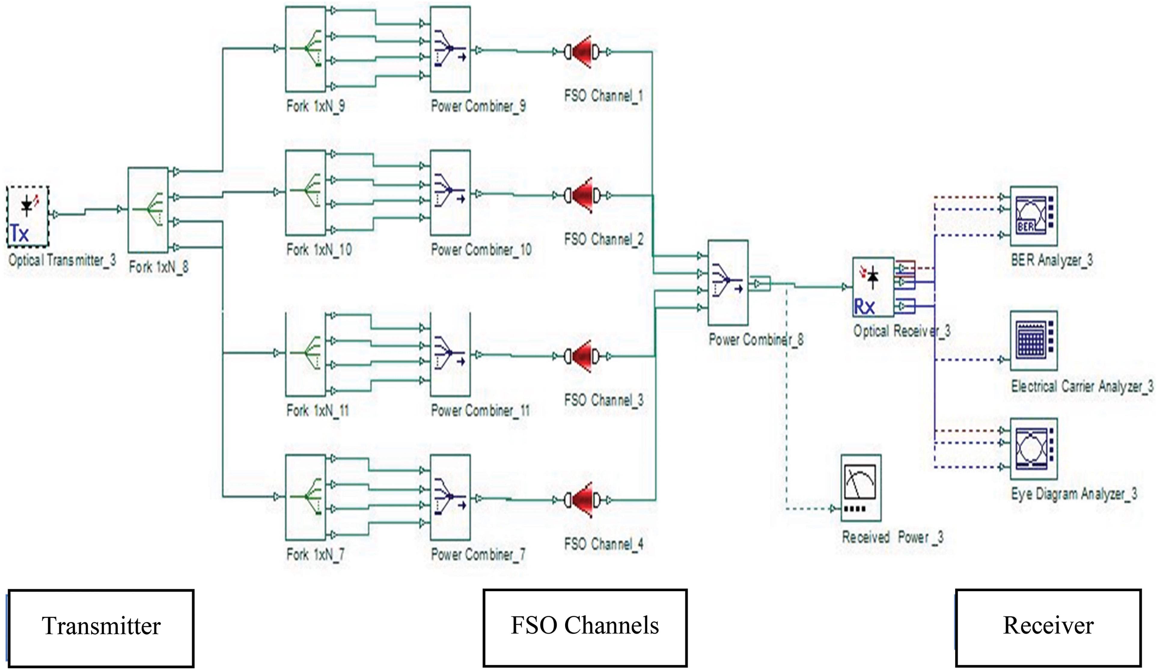
Figure 5: Example of 4Tx/1Rx G2T-FSO transmitters
The model proposed by Carbonneau is frequently employed in the estimation of rain attenuation, utilizing the rain rate R (mm/h). The model incorporates two constants, and k, which are dependent on the specific measured values. The variable γRain represents the rain attenuation per km and is defined as:
Ensuring a clear LOS between transceivers is crucial for the proper functioning of the FSO link. Therefore, a visible path is required. Fog particles play a crucial role in the absorption of photons in the Earth’s atmosphere. Their small size, which is comparable to the wavelength transmission window [35], makes them a significant factor. Fog can considerably impact link transparency, resulting in a reduced LOS range. The attenuation caused by fog can be as high as 300 dB/km, making it a key consideration in FSO link design. One common approach to estimating fog attenuation is through Mie scattering theory, which relies on measurements of atmospheric transparency, often referred to as visibility [34–36]. Fog attenuation is computed as follows:
where V represents visibility in km, λnm denotes wavelength in nm and α is the fog attenuation factor in dB/Km. The scattering size distribution, q, as defined by KIM [34], is illustrated in (34). An attenuation coefficient of 0.6 dB/km was adopted to characterize clear weather conditions, with other geometrical parameters listed in Table 2.

This section presents the performance evaluation of G2T-FSO communication link in terms of received power, SNR, BER, and eye diagram.
Fig. 6 illustrates received power levels for curved track G2T-FSO communication link with a radius of RC1(250) = 2667 m. It shows the effects of different weather conditions on received power levels along the track span.
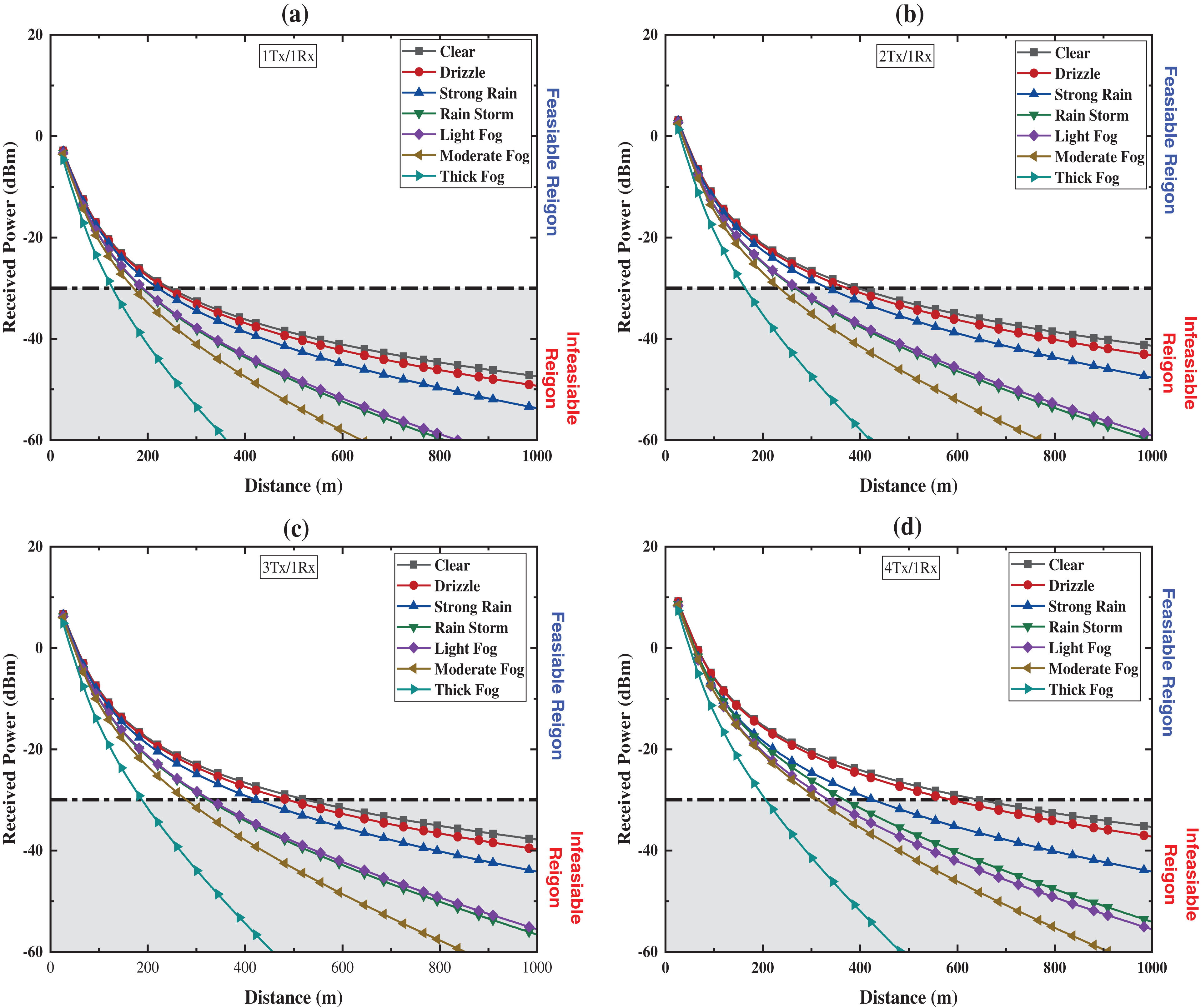
Figure 6: G2T-FSO received power for curved track link with NRZ modulation: (a) 1Tx/1Rx, (b) 2Tx/1Rx, (c) 3Tx/1Rx, (d) 4Tx/1Rx
Moreover, it is divided into two regions, namely, feasible region and infeasible region. The feasible region shows levels for acceptable link performance that achieved a BER of 10−9, however, the infeasible region shows power levels that are less than the acceptable levels.
In terms of link G2T-FSO range, under clear weather with attenuation of 0.6 dB/km power levels of −29.71, −29.05 and −29.50 dBm were achieved at ranges of 240, 365, 505, and 618 m for 1Tx, 2Tx, 3Tx, and 4Tx NRZ transmitter respectively. Furthermore, under moderate rain attenuation of 6.9 dB/km levels of −28.68, −29.50, −29.73 and −28.99 dBm at ranges of 201, 322, 388 and 399 m for single, dual, triple and quad transmitters, respectively, Moreover, under moderate fog levels of −29.32, −28.83, −28.56 and −29.10 dBm at ranges of 164, 220,260 and 301 m for the aforementioned cases, respectively.
On the other hand, in terms of weather effects on received power, under moderate rain, an average decline of −5.15 and −3.07 dBm occurred for 4Tx and 3Tx, 2Tx, 1Tx, respectively, which is equivalent to an average drop of 22%, 10.36%, 13% and 7.59% for each case, respectively. Furthermore, moderate fog causes an average power level decrease of −13.74, −13.74, −13.79 and −13.81 dBm that amounting to an average of 43.84%, 38.92%, 38.34% and 29.67% for 4Tx, 3Tx, 2Tx and 1Tx, respectively. The Quad Transmitter setup achieved the highest link range and robust performance in various weather conditions. The train communicates through all four transceivers (Tx1, Tx2, Tx3, Tx4) with the BS Transceiver (Rx1), enabling high data rates for passengers.
Acquired SNR levels of multiple receivers under variable weather conditions are illustrated in Fig. 7. It is organized into four subgroups (a), (b), (c) and (d) for single, dual, Triple, and Quad transmitters, respectively. In the case of clear weather conditions, SNR levels of 4.06, 5.39, 4.43 and 4.47 dB at ranges of 240, 265, 505, and 618 m were achieved for the cases above, respectively. Moreover, under moderate rain conditions, levels of 5.66, 4.31, 7.64, and 6.40 dB were achieved at link ranges of 201, 322, 388, and 399 m for 1Tx, 2Tx, 3Tx, and 4Tx, respectively. Lastly, under moderate fog condition SNR levels of 4.73, 6.28, 6.45, and 5.24 dB were achieved at ranges of 164, 220, 260, and 301 m.
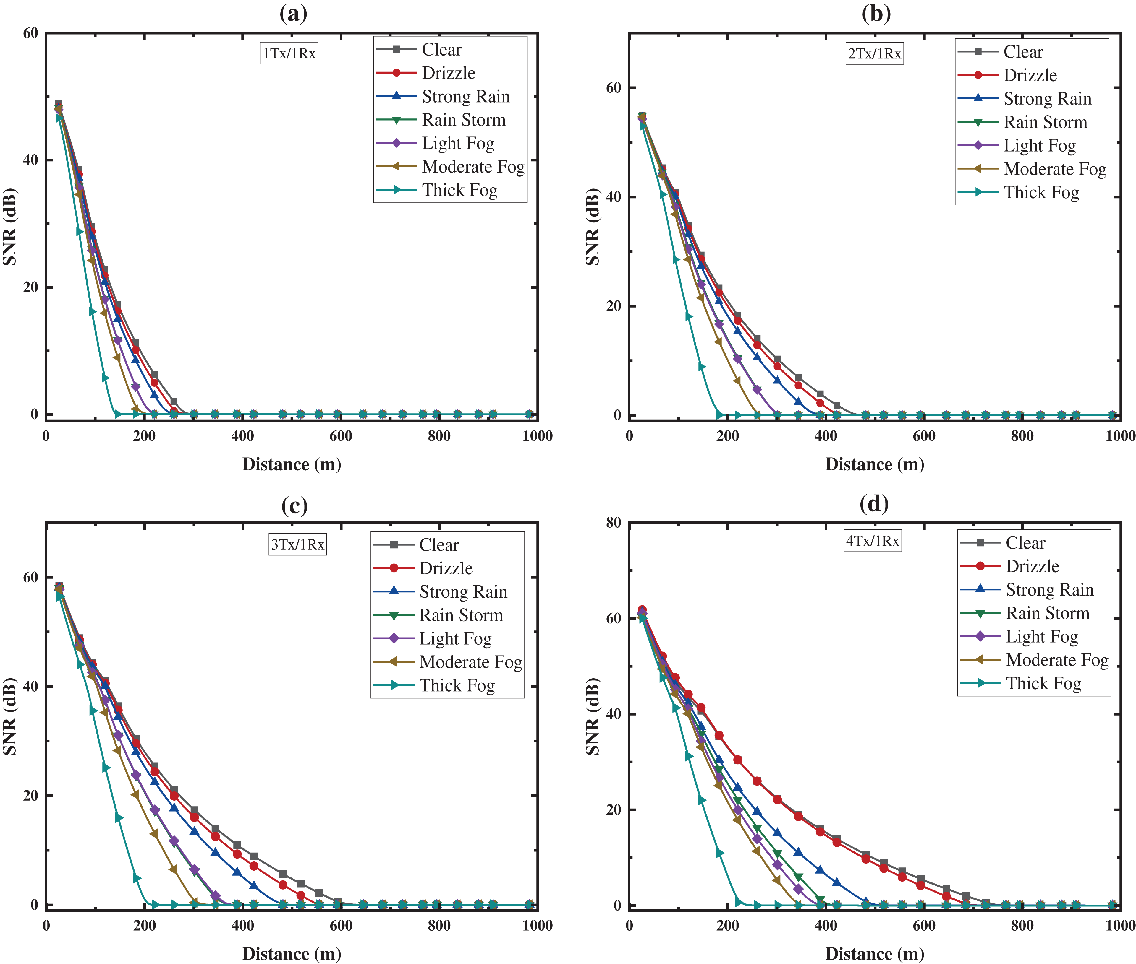
Figure 7: G2T-FSO curved track link SNR for NRZ modulation: (a) 1Tx/1Rx, (b) 2Tx/1Rx, (c) 3Tx/1Rx, (d) 4Tx/1Rx
As per international Union of Railways (UIC) standards for high-speed railways, the train-to-train communication model achieves optimal performance with a BER = 10−9 at an SNR of 5 dB or higher, meeting transmission needs for train control and prewarning messages. Simulations show that the 4Tx/1Rx configuration provides the highest SNR as the train nears the BS.
Fig. 8 shows achieved BER levels along with coverage range for a various number of G2T-FSO curved Track transmitters under different weather conditions. The BER is a key parameter for evaluating the performance of data channels, whether over radio, wireless, or wired telecommunications links. It measures the number of errors occurring in the transmitted data, with an acceptable BER typically around 10−9, indicating very low error rates at the receiving end. The graphs demonstrate acceptable BER levels of 10−9 were achievable at ranges of 240, 365, 505 and 610 m for 1Tx, 2Tx, 3Tx, and 4Tx, respectively. Additionally, under moderate rain condition, acceptable link performance was achieved at 201, 322, 388, and 399 m. Apart from rain attenuation, moderate fog acceptable link ranges were achieved at distances of 164, 220, 260 and 301 m for 1Tx, 2Tx, 3Tx, and 4Tx, respectively.
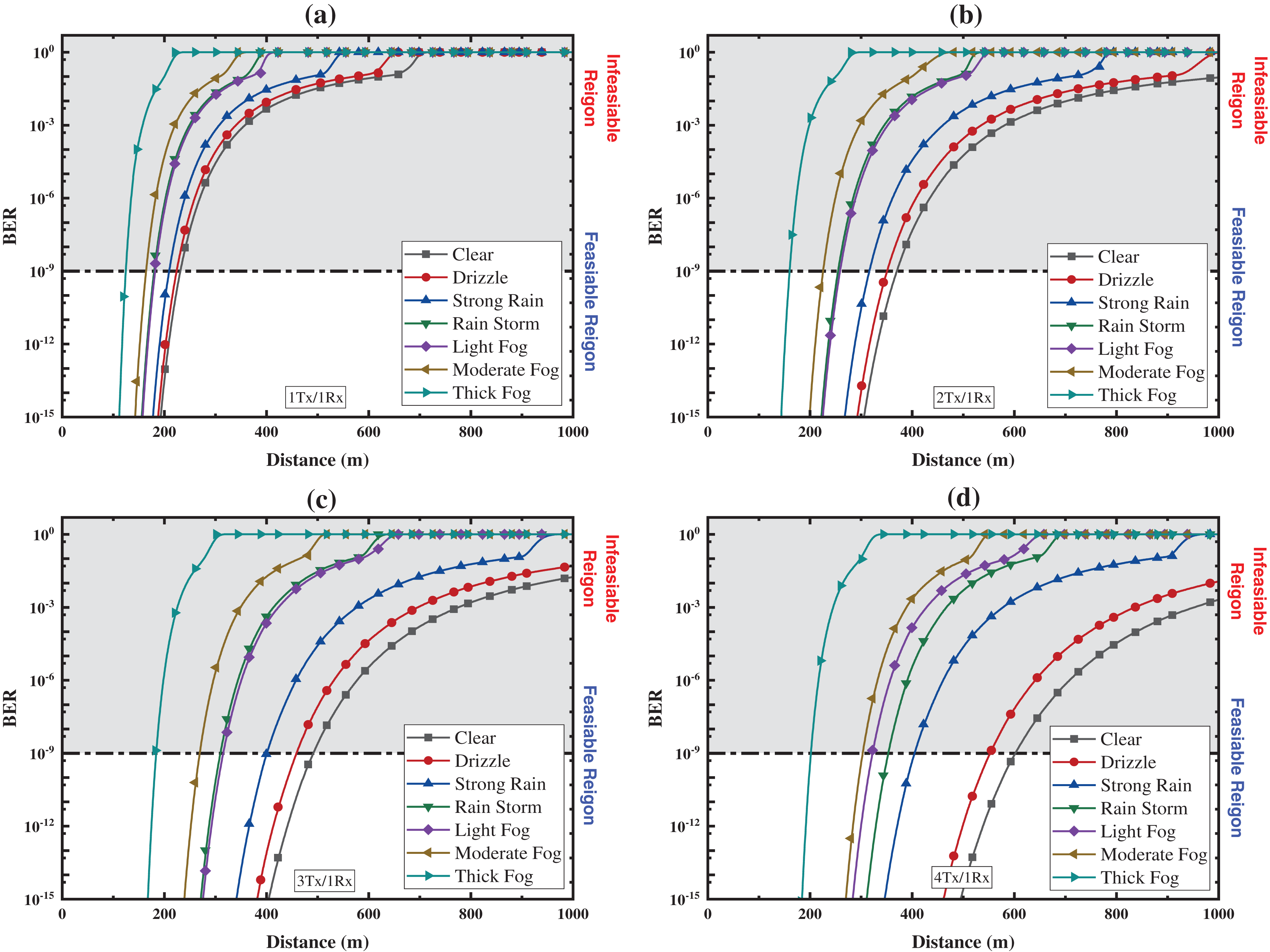
Figure 8: G2T-FSO curved track link BER for NRZ modulation: (a) 1Tx/1Rx, (b) 2Tx/1Rx, (c) 3Tx/1Rx, (d) 4Tx/1Rx
An eye diagram, used to assess signal quality, appears as a series of “eyes” between rails. Table 3 shows that the 4Tx configuration performs best under clear, moderate rain, and moderate fog conditions. All transmitter configurations show near-ideal NRZ eye openings at short distances, but eye clarity decreases with greater distance or higher weather attenuation. Moderate fog degrades performance, leading to incoherent eye diagrams at long ranges. The 4Tx configuration exhibits high tolerance to geometrical losses in clear weather but some jitter in moderate rain. The 3Tx configuration also handles weather well but is less effective than 4Tx in moderate fog.

3.3 Link Margin Analysis for Curve Track
A curved track with a radius of RC1(250) = 2667 m for link margin analysis in Fig. 9, shows resulted link margins for curved track model were estimated where it illustrates link margins for NRZ for 4Tx, 3Tx, 2Tx and 1Tx under various weather conditions. However, under clear weather link margins of 21, 22.16, 24.32 and 26.59 dB were achieved at ranges of 618, 505, 365, and 240 m for 4Tx, 3Tx, 2Tx and 1Tx utilizing NRZ modulated transmitters. This result shows how track curvature impacts FSO link stability.
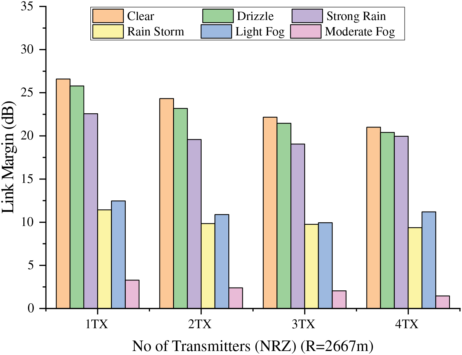
Figure 9: Link margins analysis NRZ transmitters for curved track G2T-FSO model
3.4 Comparison of Curved Track G2T-FSO Model Related Research
For the case of curved track G2T-FSO line, there is only one study that has been conducted by Paudel et al. in [8]. Table 4 shows that 4TX/1RXNRZ G2T-FSO link achieve 124% improvements, respectively.

This research paper studies the received power, SNR, BER, and eye diagrams for the G2T-FSO link for the curved track. A number of fundamental G2T-FSO link geometrical and mathematical properties were derived and defined in terms of received power and SNR. The simulation was set up to evaluate the performance of the curved track model based on multiple transmitters (1Tx/1Rx, 2Tx/1Rx, 3Tx/1Rx and 4Tx/1Rx), NRZ-OOK modulation, and different weather conditions. This research paper also provides detailed formulations for the curved track G2T-FSO model and a summary of the respective link range, attenuation, received power, and eye diagrams tabulated as in Table 3. In comparison with related work, this proposed curve G2T-FSO model link illustrated improved performance and longer coverage ranges. Although the proposed FSO technology poses many advantages there are limitations, where severe weather conditions have the potential to limit link availability, performance, and range. Therefore, based on the results, it was observed that in order to establish an acceptable link performance with the least number of base stations, increasing the number of transmitters is preferred.
Acknowledgement: The authors extend their appreciation to the Deputyship for Research & Innovation, Ministry of Education in Saudi Arabia for funding this research work through the project.
Funding Statement: This research was funded by the Deputyship for Research & Innovation, Ministry of Education in Saudi Arabia, grant number S-1443-0223.
Author Contributions: The authors confirm contribution to the paper as follows: Conceptualization, Wafi A. B. Mabrouk, Mohammed A. Alhartomi, Mohammad F. L. Abdullah and Ahmed Alzahmi; methodology, Mohammed A. Alhartomi, Mohammad F. L. Abdullah, Wafi A. B. Mabrouk and Mohammed S. M. Gismalla; software, Wafi A. B. Mabrouk and Mohammed S. M. Gismalla; validation, Mohammad F. L. Abdullah, Wafi A. B. Mabrouk and Mohammed S. M. Gismalla; formal analysis, Wafi A. B. Mabrouk and Mohammed S. M. Gismalla; investigation, Mohammed A. Alhartomi, Ahmed Alzahmi, Saeed Alzahrani and Mohammad R. Altimania; resources, Ahmed Alzahmi, Saeed Alzahrani, Mohammad R. Altimania and Mohammed S. Alsawat; data curation, Ahmed Alzahmi, Saeed Alzahrani, Mohammad R. Altimania and Mohammed S. Alsawat; writing—original draft preparation, Wafi A. B. Mabrouk, Mohammad F. L. Abdullah and Mohammed A. Alhartomi; writing—review and editing, Mohammed S. M. Gismalla, Mohammed A. Alhartomi and Mohammad F. L. Abdullah; visualization, Wafi A. B. Mabrouk, Ahmed Alzahmi and Mohammed A. Alhartomi; supervision, Mohammed A. Alhartomi and Mohammad F. L. Abdullah; project administration, Ahmed Alzahmi and Mohammed A. Alhartomi; funding acquisition, Mohammed A. Alhartomi, Ahmed Alzahmi, Saeed Alzahrani, Mohammad R. Altimania and Mohammed S. Alsawat. All authors reviewed the results and approved the final version of the manuscript.
Availability of Data and Materials: The data that support the findings of this study are available on request from the corresponding author.
Ethics Approval: Not applicable.
Conflicts of Interest: The authors declare that they have no conflicts of interest to report regarding the present study.
References
1. Al-Mohammed HA, Al-Ali M, Yaacoub E. FSO communication system for high-speed trains under varying visibility conditions. Veh Commun. 2023 Aug 01;43:100634. [Google Scholar]
2. Jeon HB, Kim SM, Moon HJ, Kwon DH, Lee JW, Chung JM, et al. Free-space optical communications for 6G wireless networks: challenges, opportunities, and prototype validation. IEEE Commun Mag. 2023;61(4):116–21. [Google Scholar]
3. Fathi-Kazerooni S, Kaymak Y, Rojas-Cessa R, Feng JH, Ansari N, Zhou MC, et al. Optimal positioning of ground base stations in free-space optical communications for high-speed trains. IEEE Trans Intell Transp Syst. 2017;19(6):1940–9. [Google Scholar]
4. Gismalla MS, Azmi AI, Salim MR, Iqbal F, Abdullah MFL, Hamdan M, et al. Optimizing optical attocells positioning of indoor visible light communication system. Comput Mater Contin. 2023;74(2):3607–25. doi:10.32604/cmc.2023.031192. [Google Scholar] [CrossRef]
5. Paudel R, Ghassemlooy Z, Le-Minh H, Rajbhandari S, Livingstone B. Investigation of FSO ground-to-train communications in a laboratory environment. In: 2011 Second Asian Himalayas International Conference on Internet (AH-ICI), 2011; Kathmundu, Nepal: IEEE; p. 1–5. [Google Scholar]
6. Mori K, Terada M, Nakamura K, Murakami R, Kaneko K, Teraoka F et al. Fast handover mechanism for high data rate ground-to-train free-space optical communication system. In: 2014 IEEE Globecom Workshops (GC Wkshps), 2014; Austin, TX, USA: IEEE; p. 499–504. [Google Scholar]
7. kaur A, Sharma N, Singh J. Selection of suitable wavelengths for the dual-wavelength model of free space optics (FSO) systems for high-speed trains. J Opt Commun. 2024;45(1):137–42. doi:10.1515/joc-2019-0180. [Google Scholar] [CrossRef]
8. Paudel R, Ghassemlooy Z, Le Minh H, Rajbhandari S, Leitgeb E. Lambertian source modelling of free space optical ground-to-train communications. In: 2012 8th International Symposium on Communication Systems, Networks & Digital Signal Processing (CSNDSP), 2012; Poznan, Poland: IEEE; p. 1–5. [Google Scholar]
9. Paudel R, Poliak J, Ghassemlooy Z, Wilfert O, Leitgeb E. Curved track analysis of FSO link for ground-to-train communications. Radioengineering. 2014;23(1):452–9. [Google Scholar]
10. Paudel R, Ghassemlooy Z, Le-Minh H, Rajbhandari S. Modelling of free space optical link for ground-to-train communications using a Gaussian source. IET Optoelectron. 2013;7(1):1–8. [Google Scholar]
11. Saini E, Bhatia R, Prakash S. High speed broadband communication system for moving trains using free space optics. In: International Conference on Computational Techniques in Information and Communication Technologies (ICCTICT), 2016; New Delhi, India: IEEE; p. 47–50. [Google Scholar]
12. Fan Q, Ansari N, Feng J, Rojas-Cessa R, Zhou M, Zhang T. Reducing the number of FSO base stations with dual transceivers for next-generation ground-to-train communications. IEEE Trans Vehicular Technol. 2018;67(11):11143–53. [Google Scholar]
13. Mabrouk WA, Abdullah M, Gismalla M. Geometric loss analysis for single curve track FSO ground to train communications link. In: 2021 IEEE Asia-Pacific Conference on Applied Electromagnetics (APACE), 2021; Penang, Malaysia: IEEE; p. 1–4. [Google Scholar]
14. Jimenez F, Aparicio F, Paez J. Evaluation of in-vehicle dynamic speed assistance in Spain: algorithm and driver behaviour. IET Intell Transp Syst. 2008;2(2):132–42. [Google Scholar]
15. Garg V, Dukkipati R. Lateral stability of railway vehicles on tangent track. Dyn Railway Veh Syst. 1984:225–62. [Google Scholar]
16. Mundrey J. Railway track engineering. 4thed. India: Tata McGraw-Hill Education; 2009. vol. 6, p. 154–88. [Google Scholar]
17. Pyrgidis C. Railway transportation systems: design, construction and operation. 2nd ed. Boca Raton, FL, USA: CRC Press Taylor & Francis Group; 2016. vol. 12, p. 279–308. [Google Scholar]
18. Gheth W, Rabie KM, Adebisi B, Ijaz M, Harris G. Communication systems of high-speed railway: a survey. Trans Emerg Telecomm Technol. 2021;32(4):e4189. doi:10.1002/ett.4189. [Google Scholar] [CrossRef]
19. Joly R, Pyrgidis C. Rail vehicle running through curves guiding forces. Rail Int. 1990;12:11. [Google Scholar]
20. Le Pen L, Powrie W. The railway track system: performance and trackbed design. In: Sustainable railway engineering and operations, Leeds: Emerald Publishing Limited; 2022. p. 61–89. [Google Scholar]
21. Yang L, Eom S, Suzuki T. Measuring railway network performance considering accessibility levels in cities worldwide. J Transp Geogr. 2021;96(1):103211. doi:10.1016/j.jtrangeo.2021.103211. [Google Scholar] [CrossRef]
22. Mohan N, Abadi MM, Ghassemlooy Z, Zvanovec S, Hudson R, Bhatnagar MR. Sectorised base stations for FSO ground-to-train communications. IET Optoelectron. 2020;14(5):312–8. doi:10.1049/iet-opt.2019.0155. [Google Scholar] [CrossRef]
23. Pyrgidis C, Demiridis N. The effects of tilting trains on the track superstructure. In: IET International Conference on Railway Condition Monitoring, 2006 Nov 29–30; Brimingham, UK. [Google Scholar]
24. Brustad TF, Dalmo R. Railway transition curves: a review of the state-of-the-art and future research. Infrastructures. 2020;5(5):43. doi:10.3390/infrastructures5050043. [Google Scholar] [CrossRef]
25. Bloom S, Korevaar E, Schuster J, Willebrand H. Understanding the performance of free-space optics. J Opt Netw. 2003;2(6):178–200. [Google Scholar]
26. Kahn JM, Barry JR. Wireless infrared communications. Proc IEEE. 1997;85(2):265–98. [Google Scholar]
27. Elganimi TY. Studying the BER performance, power-and bandwidth-efficiency for FSO communication systems under various modulation schemes. In: 2013 IEEE Jordan Conference on Applied Electrical Engineering and Computing Technologies (AEECT), 2013; Amman, Jordan: IEEE; p. 1–6. [Google Scholar]
28. Xu F, Khalighi M-A, Bourennane S. Impact of different noise sources on the performance of PIN-and APD-based FSO receivers. In: Proceedings of the 11th International Conference on Telecommunications, 2011; Graz, Austria: IEEE; p. 211–8. [Google Scholar]
29. He J, Norwood RA, Brandt-Pearce M, Djordjevic IB, Cvijetic M, Subramaniam S, et al. A survey on recent advances in optical communications. Comput Electr Eng. 2014;40(1):216–40. [Google Scholar]
30. Khalighi MA, Uysal M. Survey on free space optical communication: a communication theory perspective. IEEE Commun Surv Tutorials. 2014;16(4):2231–58. [Google Scholar]
31. Petković MI, Đorđević GT, Milić DN. BER performance of IM/DD FSO system with OOK using APD receiver. Radioengineering. 2014;23(1):480–7. [Google Scholar]
32. Ghassemlooy Z, Popoola W, Rajbhandari S. Optical wireless communications: system and channel modelling with Matlab®. Boca Raton, FL, USA: CRC Press; 2019. [Google Scholar]
33. Stotts LB, Kolodzy P, Pike A, Graves B, Dougherty D, Douglass J. Free-space optical communications link budget estimation. Appl Opt. 2010;49(28):5333–43. doi:10.1364/AO.49.005333 [Google Scholar] [PubMed] [CrossRef]
34. Mabrouk WA, Abdullah M, Gismalla M. Enhancement of link range for FSO ground to train communications using multiple transmitters concept. In: 2019 International Conference on Information Science and Communication Technology (ICISCT), 2019; Karachi, Pakistan: IEEE; p. 1–7. [Google Scholar]
35. Achour M. Simulating atmospheric free-space optical propagation: II. Haze, fog, and low clouds attenuations. In: Optical wireless communications V, Washington, DC, USA: SPIE; 2002. vol. 4873, p. 1–12. [Google Scholar]
36. Song H, Wu W, Dong H, Schnieder E. Propagation and safety analysis of the train-to-train communication system. IET Microw, Antenn Propagat. 2019;13(13):2324–9. doi:10.1049/iet-map.2018.6074. [Google Scholar] [CrossRef]
Cite This Article
 Copyright © 2024 The Author(s). Published by Tech Science Press.
This work is licensed under a Creative Commons Attribution 4.0 International License , which permits unrestricted use, distribution, and reproduction in any medium, provided the original work is properly cited.


 Submit a Paper
 Propose a Special lssue
 View Full Text
 Download PDF
 Downloads
 Citation Tools