 Open Access
ARTICLE
Reliability Prediction of Wrought Carbon Steel Castings under Fatigue Loading Using Coupled Mold Optimization and Finite Element Simulation
1 Mechanical Engineering Department, Prince Mohammad Bin Fahd University, Alkhobar, 34754, Saudi Arabia
2 Mechanical Engineering Department, King Fahd University of Petroleum and Minerals, Dhahran, 31261, Saudi Arabia
3 Interdisciplinary Research Center for Intelligent Manufacturing and Robotics, King Fahd University of Petroleum and Minerals, Dhahran, 31261, Saudi Arabia
4 Interdisciplinary Research Center for Advanced Materials, King Fahd University of Petroleum and Minerals, Dhahran, 31261, Saudi Arabia
5 Interdisciplinary Research Center for Industrial Nuclear Energy, King Fahd University of Petroleum & Minerals, Dhahran, 31261, Saudi Arabia
* Corresponding Author: Syed Sohail Akhtar. Email:
(This article belongs to the Special Issue: Recent Advances in Computational Methods for Performance Assessment of Engineering Structures and Materials against Dynamic Loadings)
Computer Modeling in Engineering & Sciences 2024, 141(3), 2325-2350. https://doi.org/10.32604/cmes.2024.054741
Received 06 June 2024; Accepted 20 September 2024; Issue published 31 October 2024
Abstract
The fatigue life and reliability of wrought carbon steel castings produced with an optimized mold design are predicted using a finite element method integrated with reliability calculations. The optimization of the mold is carried out using MAGMASoft mainly based on porosity reduction as a response. After validating the initial mold design with experimental data, a spring flap, a common component of an automotive suspension system is designed and optimized followed by fatigue life prediction based on simulation using Fe-safe. By taking into consideration the variation in both stress and strength, the stress-strength model is used to predict the reliability of the component under fatigue loading. Under typical loading conditions of 70 kN, the analysis showed that 95% of the steel spring flaps achieve infinite life. However, under maximum loading conditions of 90 kN, reliability declined significantly, with only 65% of the spring flaps expected to withstand the stress without failure. The study also identified a safe load-induced stress of 95 MPa on the spring flap. The findings suggest that transitioning from forged to cast spring flaps is a promising option, particularly if further improvements in casting design reduce porosity to negligible levels, potentially achieving 100% reliability under typical loading conditions. This integrated approach of mold optimization coupled with reliability estimation under realistic service loading conditions offers significant potential for the casting industry to produce robust, cost-effective products.Keywords
Steel shares a major portion of metal casting tonnage (~10 million tons) owing to its availability and mechanical properties [1]. Despite such prevalence in use, steel castings are often produced with defects that arise due to poor mold design, improper selection of process parameters, process-related variabilities, uncontrolled solidification, etc. Identifying and minimizing these defects in the casting design phase is essential to obtain high-quality castings. This can be achieved through casting simulation tools which allow designers to develop a robust mold by examining the filling and solidification behavior, defect prediction and minimization, and even microstructure evolution and mechanical properties of the final cast product. However, a critical question that has remained so far is how to accurately predict castings’ mechanical performance and reliability in service. On a physical level, such predictions are challenging because of the lack of testing equipment that can exactly replicate the actual loading conditions on each cast part in service. Thus, it brings about a need for integrated simulations capable of incorporating the casting simulation results (especially defects) into mechanical performance simulations and reliability assessments to become confident in the efficient use of a cast part for its desired service life.
A wide range of engineering applications use wrought carbon steel castings because of their cost-effectiveness and superior structural properties. However, a crucial component that establishes their dependability and longevity is how well they function under fatigue loading. Fatigue loading has the potential to start and spread cracks, which could ultimately result in the component failing. For this reason, predicting these castings’ fatigue reliability is crucial to guarantee their safe and effective use. Recent studies have highlighted the importance of understanding the fatigue behavior of steel components under various conditions. For instance, a study on the low fatigue response of crest-fixed cold-formed steel drape curved roof claddings demonstrated the susceptibility of such structures to fatigue damage, emphasizing the need for comprehensive fatigue analysis [2]. Similarly, an experimental study on the high-cycle fatigue behavior of butt welds made of corroded AISI 304 stainless steel and Q460 high-strength steel showed significant differences in fatigue performance due to corrosion effects, underscoring the complexity of fatigue phenomena in steel structures [3]. Previous research has demonstrated the effectiveness of integrating various methodologies for improving the performance of steel components. For example, studies have shown that optimizing welding parameters and using advanced simulation techniques can significantly improve the fatigue life of welded structures [4]. These findings highlight the potential of combining process optimization with simulation tools to achieve better performance and reliability in steel castings.
Numerous casting layouts have been designed and optimized using simulation tools so that a reliable mold can be developed to produce parts with little to no defects. Mostly, either a part of the mold or a casting process parameter is optimized to improve the quality of cast products. Khan et al. [5,6] reported optimization of industrial components using CAD modeling and casting simulation using MAGMASoft to predict and minimize casting defects such as porosity and hotspots. They obtained reasonable agreement with the experimental data. Bhatt et al. [7] and Kermanpur et al. [8] have demonstrated that the design optimization of the feeding system and solidification simulation can ensure better quality of castings. Mi et al. [9] performed numerical analysis on the casting’s mold-filling and solidification phases. They replicated the solidification process, distribution of thermal stress, and filling behavior, and predicted potential flaws like shrinkage and cold shut. Khade et al. [10] examined the casting of brake discs to address the issue of reduced casting yield brought on by overly engineered gating system components. They modified the gating system to address this issue by considering casting simulation, theoretical knowledge, gating principles, and gating design techniques. Choudhari et al. [11] used Vector Gradient Method (VGM)-based AutoCAST X software for simulation and optimization of the component suffered from shrinkage porosity defect leading to premature failure. The numerical simulation software has all the design parameters set correctly, therefore the feeder’s total shrinkage porosity should shift. It has been reported [12,13] that the impact of heat flow through the mold walls on casting quality is the main topic of this research. Reverse engineering is used to determine heat transfer coefficients, and this method is detailed. Typically, because of incomplete information, a heat transfer coefficient that is constant from the bottom to the top of the ingot is considered between the solidifying shell and the mold surface. Rajkumar et al. [14] studied the multi-gate variants in the sand casting process to minimize defects. Multiple configurations were experimented and simulated such as side sprue serial and parallel connections (SSSC & SSPC), center sprue serial and parallel connections (CSSC & CSPC), and center sprue runner extension parallel connections (CS-RE-PC). The visual inspection revealed CS-RE-PC to be the most suitable design for a multi-cavity application owing to the best possible flow rate and nearly defect-free casting. Ayar et al. [15] employed simulations to study the effect of feeder system design using plates of varying thickness as cast parts. Shrinkage porosities are reported inside the middle feeder for all plate thicknesses. However, the entire defect was inside the feeder which did not affect the feeding efficiency and feedability index. Casting quality and yield are also found to be decreased with increasing thickness. It is reported that simulation results matched well with the experiments which confirms an efficient model to perform analyses for other casting geometries. Patil et al. [16] used Auto-CastX1 software to simulate the casting of a center plate, which resulted in devising a new method of casting those plates with a drop-in rejection rate from 8.5% to 3.5%. It is inferred that simulations are essential in developing affordable, high-quality, and reliable cast products. Hodbe et al. [17] optimized the casting design to deal with volumetric shrinkage and yield problems in a contact wheel. Major defects observed are shrinkage, blowhole, and pinhole. Auto-Cast software is used to optimize feeder design and location, porosity minimization, blowhole minimization via adequate venting, eradicating gas entrapment issues, and proper gating and riser system design. The final design of the mold resulted in an improved yield of ~90%. Bekele et al. [18] studied the riser design to minimize the shrinkage porosities in a sprocket gear. The gating system is designed with the modulus method and the model was developed in CATIA. The casting process is simulated using ProCAST where it is found that position and feed volume of risers are the key factors to reduce porosity concentration. The quality of sprocket gears is reported to improve significantly with a modified riser design.
The Finite Element Method (FEM) is widely applied in materials science to simulate and analyze the behavior of materials under various conditions. It allows for the prediction of stress, strain, deformation, and other critical properties by solving complex equations that describe the material’s response to external forces [19]. FEM is particularly valuable in studying material failure, optimizing manufacturing processes, and designing materials with specific properties. It is used in applications ranging from predicting the fatigue life of materials to optimizing the microstructure of composites and metals, thereby enhancing their performance and reliability in practical applications. To comprehend the behavior of plastic deformation under compression, FEM simulation provides the evolution of effective stress, strain, and displacement [20]. Fatigue life prediction of cast components including defects has been reported in the literature previously. Beckermann et al. [21] used simulations to determine the fatigue life of castings with porosities. The porosity obtained by radiographic examination is reconstructed in ABAQUS simulations. It is concluded that, for a more realistic fatigue life prediction, both the magnitude and distribution of porosity should be considered in the simulations. In another study by Hardin et al. [22], casting simulations are integrated with performance simulations. Standard specimens are cast, tested, and simulated in the presence of defects, where an excellent agreement in the experimental and simulated results has led to a case study on casting design optimization of an actual cast part. Sheikh et al. [23] and Khan et al. [24] predicted the reliability of cast specimens under fatigue loading by taking into account the variability in both the stress and strength models. They found that casting simulations for mold design optimization can produce castings that are almost entirely free of defects and have fatigue lifetimes comparable to those of their sound equivalents. Foglio et al. [25] described the mechanical characterization of ductile irons that had solidification durations of up to 20 h. They tried to determine which process and metallurgical parameters had the most impact on the increase in fatigue strength. Ferro et al. [26] experimentally determined the high cycle fatigue properties of EN-GJS-400 ductile cast iron with chunky graphite. They discovered that the fatigue strength characteristics of the cast iron under study are not considerably affected by a mean percentage of 40% chunky graphite in the microstructure relative to the overall graphite content. Azeez et al. [27] studied the reliability and property improvement of castings through gating system design. The effect of pouring temperature is examined on fluidity and gating system design. It is reported that the strength of castings is not much dependent on the in-gate design. Moreover, ductility also depends more on the melt instead of in-gate design. In total, expanding gate design are found to be better than pressurized gate designs. Regression analysis revealed no random distribution about the reference point. The reliability-based design optimization of process parameters using the Markov chain model was recently described by Chaudhari et al. [28]. Casting failures are mapped with casting process parameters using a range of casting defects. It is concluded that using the probabilities of process parameters and casting failures, a prediction model for casting process failure may be developed. Khan et al. [29] presented a cradle to grave analysis, i.e., from mold design to failure of a valve body using simulations. The mold design is optimized for porosity minimization in MAGMASoft, fatigue life, and reliability of the valve body are determined using ABAQUS [30] and Fe-safe [31]. Based on reliability computations, a region of safe loading on the valve body is also calculated.
This paper employs a simulation-based approach which was developed and validated previously [24,32] to determine the fatigue life and reliability of a steel spring flap as shown in Fig. 1. The mold design for the spring flap is optimized to minimize defects, especially porosity, after which the fatigue life and reliability of the part are calculated using integrated simulations. Since the methodology has been developed and validated earlier as mentioned above, the complete cradle-to-grave analysis of spring flap from mold design to failure and reliability assessment is done in a virtual domain using simulations. Section 2 discusses the mathematical models used in casting simulation and finite element analysis of fatigue life prediction. Section 3 details the materials and methodology used in this study. The mold design and optimization process are explained in Section 3. Section 4 reflects on finite element modeling and fatigue life prediction. Reliability assessment is discussed in Section 4. Conclusions are drawn and future prospects of the study are presented in Section 5 of the paper.
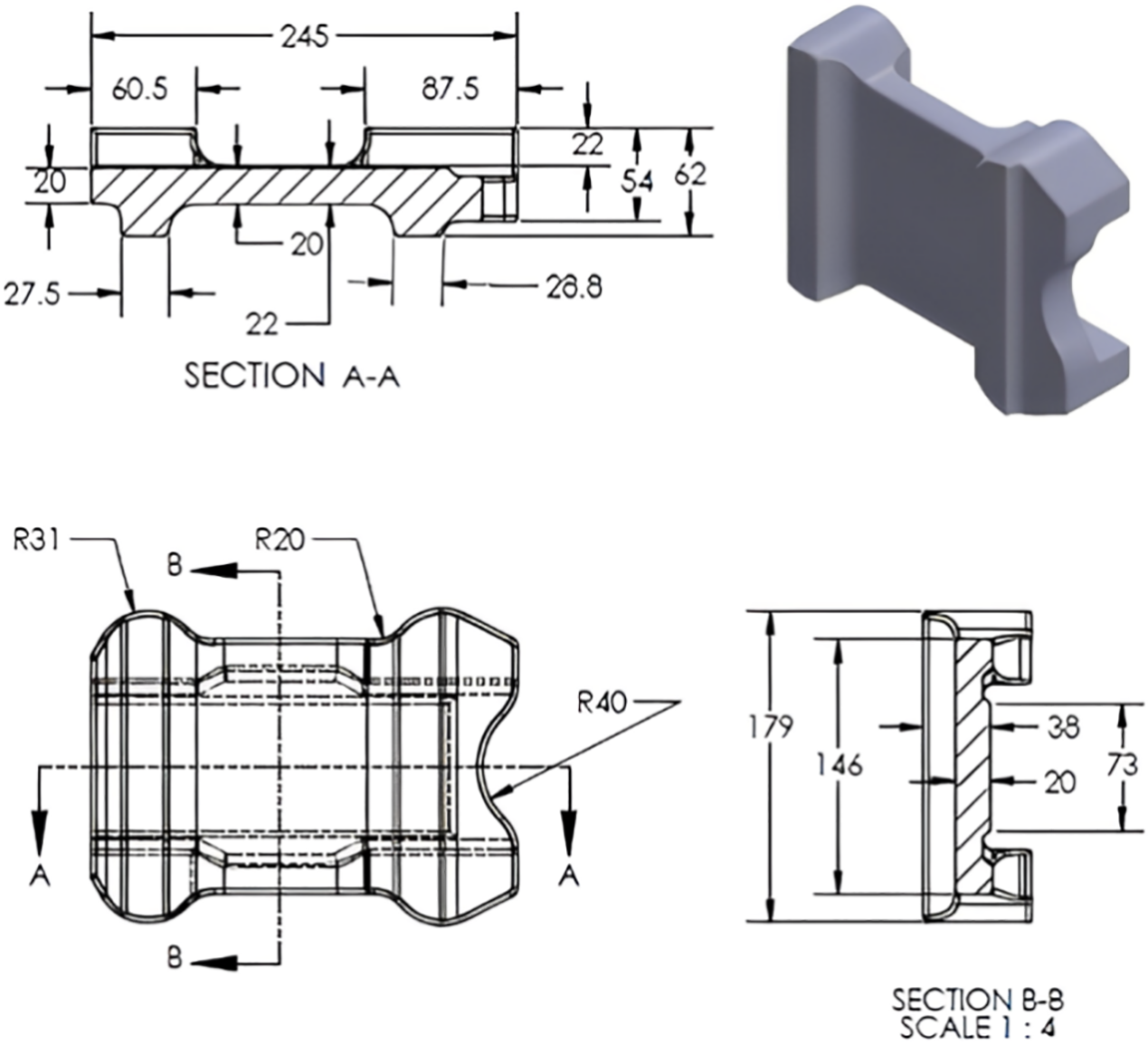
Figure 1: Steel spring flap
Casting simulations are used to optimize mold design, casting process parameters, and cast product quality. The molten metal is thought to be an incompressible fluid with temperature-dependent and laminar flow characteristics. The continuity, momentum, and energy equations (Eqs. (1) to (3)) are used to simulate the mold being filled with liquid metal. The enthalpy porosity technique incorporates the phase transition and solidification phenomena, with the latent heat release specified by the specific enthalpy function (Eq. (4)). The thermal shrinkage and mismatch stresses generated during the casting process are calculated using the local-force balance equation (Eq. (5)). The conservation equations may be represented as follows:
Here,
Here,
The thermal conductivity (
Then, the specific heat capacity (
Here:
The solidification shrinkage defects (such as pores, cavities, etc.) are calculated according to the famous Niyama criterion [33], which represents the ratio of thermal gradient,
MAGMASoft software package [33] is utilized to optimize mold design and cast quality. Simulation of the filling and solidification process requires the geometry of the casting process is available in 3D CAD files.
2.2 Finite Element Formulation for Fatigue Life Prediction
On a microscopic scale, ductile materials fracture via the mechanisms of void nucleation, growth, and coalescence. Voids can exist as microporosity or form from inclusions like second phase particles. Once nucleated, the spaces expand with increasing plastic strain. As a result, the void (or porosity) volume fraction increases. The interaction between voids begins at a critical porosity volume fraction. With increasing plastic strain, local necking and coalescence occur in the materials between voids, resulting in collapse via a connected chain of voids. Fracture of material occurs at a specific porosity fraction known as failure porosity volume fraction.
The model employed in this work is based on the linear small strain theory, which assumes that the total strain tensor (
Here,
The plasticity and failure are modeled using the porous metal plasticity model in ABAQUS. A comprehensive description of the model can be found in previous works [34–36] the ABAQUS manual [30], with the numerical integration method utilized in the software proposed by Aravas [37] To apply this model, the hardening behavior must be defined using true stress-strain data derived from tensile tests on sound (pore-free) steel. The yield condition used by the model is:
where,
It is assumed that plastic flow is normal to the yield surface defined by Eq. (8) for a given porosity fraction
Here,
Here, the first term on the right-hand side represents the growth in existing voids based on the current void fraction
The nucleation function
The value of
To effectively use the coalescence and failure model, it is crucial to determine two additional parameters: the critical porosity fraction
The fatigue life of test specimens is estimated by first predicting the porosity field using MAGMASoft and applied to the nodes of the finite element model followed by getting the elastic properties at each node according to the porosity percentage. The finite element stress analysis is then performed on each specimen under the load employed in fatigue testing. The resulting stress field which corresponds to tension and compression, is fed into the life prediction software, which does a multi-axial strain-life analysis.
Using the stress field resulted from ABAQUS simulations run with
The Brown-Miller technique, which uses planes oriented at 45 degrees to the surface and perpendicular to the surface, is thought of as a cautious method for fatigue life prediction. By resolving the following equation [31] at each node, this method uses critical plane analysis to predict the fatigue life in terms of reversals to failure
With Morrow mean stress correction, Eq. (14) is modified to:
Here,
Wrought carbon cast steel (ASTM A216 WCB), which is often used in casting engineering components due to an excellent combination of strength and ductility, was chosen as the material for the spring flap. Table 1 lists the material’s composition and properties. The testing equipment for determining the mechanical performance and reliability of spring flap under anticipated loading conditions is challenging due to design, fabrication, and even economic unfeasibility. Therefore, it is decided to use an already developed and experimentally validated methodology [24,32] towards the mold design optimization and fatigue life prediction of the selected spring flap. In addition, reliability assessment is done as per the loading scenarios provided by the end-user. Fig. 2 shows a flowchart of the methodology used in this study. The following sub-sections briefly describe the above-mentioned simulation-based methodology [24,32] developed and experimentally validated for simple cast geometries, i.e., standard tensile and fatigue specimens.


Figure 2: Steps involved in simulation-based mold design, fatigue life, and reliability estimation of spring flap
3.1 Development of Optimized Mold Design and Actual Specimens
The mechanical characterization of cast parts is often carried out by extracting the specimens from already produced castings. However, in this study, the prime objective was to optimize the whole casting process for producing high-quality and nearly defect-free castings. Therefore, standard specimens for tensile and fatigue testing are selected as simple cast parts. Multi-cavity molds capable of producing eight specimens at a time are designed and simulated, the results of which led to the modification in the mold designs resulting in nearly no defects in the final cast specimens. The details of the mold design process are already presented in [24,32]. Fig. 3 shows the final mold designs for each specimen type where no porosities are observed in any of the specimens. Casting of specimens is done using the final mold design in a local foundry after which the specimens are brought to their final dimensions as per the standards, i.e., ASTM E-8 for tensile testing and ASTM E-466 for fatigue testing.
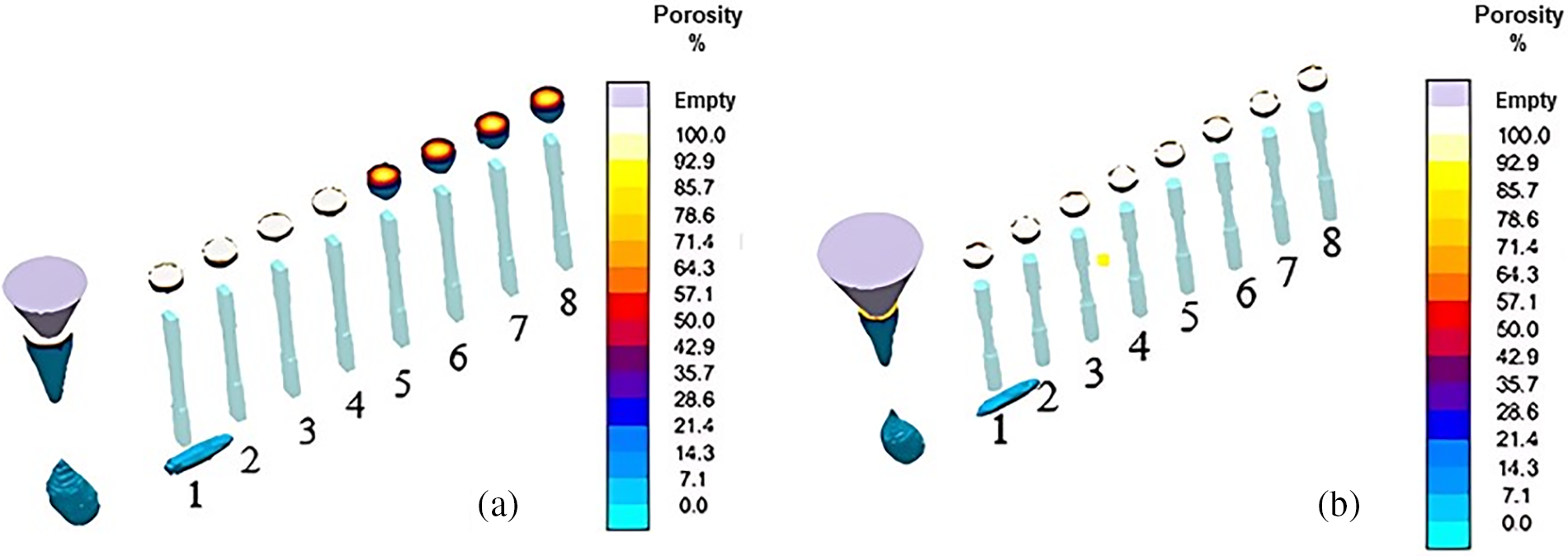
Figure 3: MAGMASoft simulation results for porosity prediction (X-ray view) for (a) tensile specimens and (b) fatigue specimens
3.2 Experiments and Simulations Pertaining to Tensile Testing
In this stage, five out of eight prepared specimens are tested under tension and compared with the tensile properties already obtained for sound steel specimens. It is observed that cast specimens have some reduced and ductility when compared to the sound specimen. It is inferred that it could be due to a complex stress field developed as a result of loading the specimens. Hence, the tensile testing is simulated in ABAQUS using the elastic-plastic material model and porous metal plasticity parameters to analyze the exact stress-strain behavior of specimens. For base case with no porosity, i.e., sound specimen, an excellent agreement is found in the measured and simulated results as shown in Fig. 4 which suggested the adequacy of the model for using it even for the specimens with porosity predicted by the software. A comparison of simulated and experimental results for all specimens is presented in [32], where strength and elongation in each specimen are found to be greater than 485 MPa and 22% respectively which are the minimum values as per the ASTM A216 standard steel. Some discrepancies in the experimental and simulated results are observed for which the possible reasons are also discussed in [32].
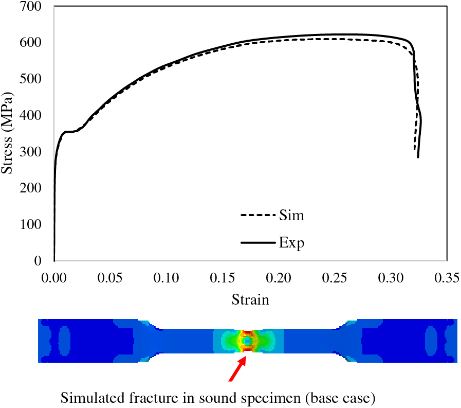
Figure 4: Experimental vs. simulated stress-strain curve and fracture in sound steel specimen
3.3 Experiments and Simulations Pertaining to Fatigue Testing
Fatigue loading refers to the application of cyclic stresses on a material over time, which can lead to the initiation and propagation of cracks. This process can ultimately result in failure at stress levels much lower than the material’s ultimate tensile strength. For carbon steel castings, fatigue loading is critical as it directly influences the lifespan and reliability of components subjected to repetitive loading in-service conditions. Finite element simulation is a powerful computational tool that helps in understanding the behavior of materials under fatigue loading by allowing detailed analysis of stress distribution, strain, and crack propagation within the material. Finite element simulation can simulate the cyclic loading conditions and predict the locations and growth of potential fatigue cracks. This helps in identifying critical areas and optimizing design and process parameters to enhance the fatigue performance of carbon steel castings. By integrating mold optimization with finite element simulation, our approach aims to predict and mitigate fatigue failure indicators. The fatigue testing is done for seven specimens under fully reversed conditions with R = −1. All specimens are tested under 5 Hz frequency until fracture or the runout condition which is 1 million (106) cycles in this work. The stress amplitudes are carefully selected to have at least one specimen obtaining infinite life (more than 106 cycles). More details on fatigue experiments and results are included in [24]. Fatigue testing is also simulated using ABAQUS and compared with the experimental results. The porosity estimates in MAGMASoft are moved to the nodes of an already developed FEA mesh where the elastic properties are degraded [32]. Next, the stress amplitude for each fatigue specimen is used to simulate the elastic stress analysis. Finally, Fe-safe is used to determine the number of cycles to failure for each specimen. For steel specimens, the Brown-Miller fatigue model with Morrow mean stress correction is used [31]. Experimental and simulated results are compared as shown in Fig. 5 which are encouraging yet non-conservative in steel specimens [24].
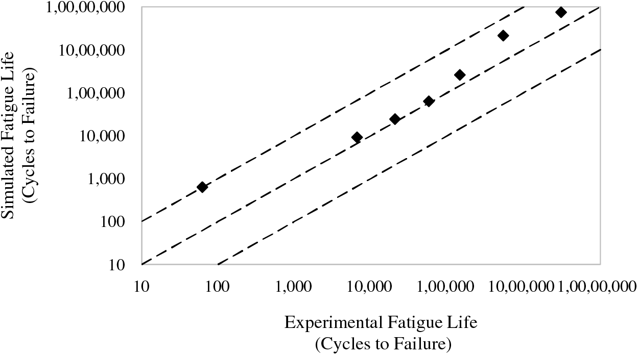
Figure 5: A comparison of measured and precited fatigue life of standard WC steel samples
Reliability analysis in this methodology is based on the classical stress-strength interference model. Fig. 6 displays a flowchart of the reliability analysis. These reliability computations are done for both time-independent and time-dependent load-induced stress with later being more accurate as it includes the variability in stress with time [24]. Based on the predicted loading conditions on steel castings, four different stress values—79, 87, 96, and 104 MPa—are selected for time-independent load-induced stress. When calculating the likelihood of success or failure for a specific life, Fe-safe considers the variability in both material strength and loads. For time-dependent load-induced stress, the same model is used, however, the stress in this case is limited to be modeled by Rayleigh distribution using analytical methods [39]. The only difference is in the value of the shape parameter ‘β’ of Weibull and Rayleigh distribution because for later, βs = 2βσ, where βs and βσ are the shape parameters for strength and stress, respectively. The reliability function is as follows:
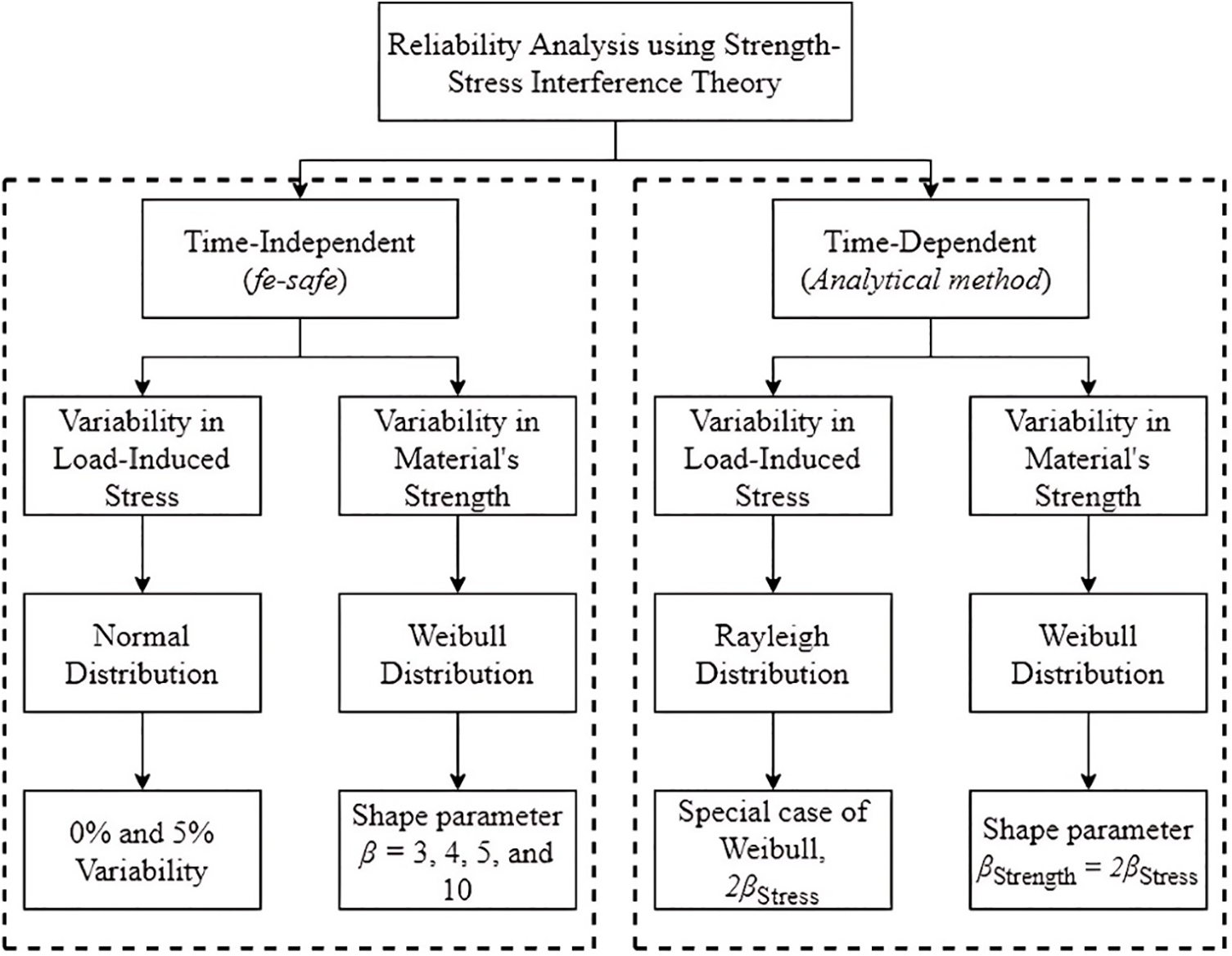
Figure 6: Flowchart of reliability evaluation
The ratio of scale parameters can be used to estimate reliability, i.e., θS/θσ for the targeted lives. Here, the θS/θσ ratio is approximated to be similar to that of the Sσ ratios for the targeted lives.
The reliability estimates led to the determination of safe load-induced stress for steel [24]. More than 86% of components are reported to survive for an infinite life, independent of β, at load-induced stress of 85 MPa, which is undoubtedly a conservative estimate of safe loading. With increasing β, it is found that over 95% of components may work safely at a load-induced stress of 95 MPa as shown in Fig. 7a. Hence, up to 95 MPa could be reasonably considered as safe stress for an infinite service life of cast steel parts, one of which will be presented next in this paper. Moreover, for time-dependent load-induced stress, it is reported that reliability is a function of design factor. A design with strength ‘S’ four times the applied stress ‘σ’ can lead to a 90% probability of survival of components which can drop to 54.5% when S is equal to σ as shown in Fig. 7b.
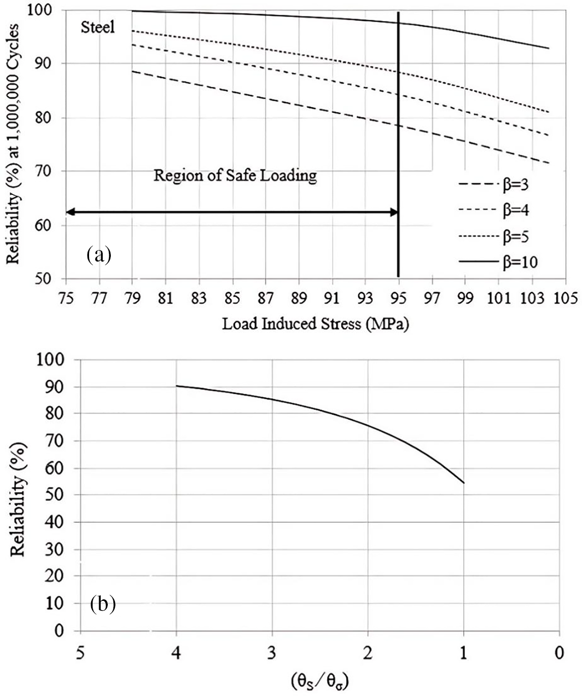
Figure 7: (a) Safe load-induced stress for cast steel and (b) Results of reliability for time-dependent load-induced stress
The methodology discussed above from Sections 3.1 to 3.4 is applied to steel spring flap, the results of which are presented in the forthcoming sections.
4.1 Optimization of Mold Design of Spring Flap
The benefit of producing multiple parts in a single casting run encouraged to design a multi-cavity mold as shown in Fig. 8. Initially, the mold is designed as per casting standards in a conventional way as practiced in a foundry. It is decided to include four flaps in a single mold which is designed using a gate-runner approach where each individual cast part is choked by its associated gate. In addition to other parts of the mold such as the pouring basin, sprue, runners, and gates, the mold also included top risers owing to their higher efficiency [40]. The parameters optimized in the mold design for castings include; gate and runner design to ensure the proper flow of molten metal to fill the mold cavities uniformly without causing turbulence, pouring basin and sprue dimensions to optimize and control the flow rate and reduce the risk of air entrapment and oxidation, risers design for their higher efficiency in feeding the molten metal to compensate for shrinkage during solidification, and the cooling rate adjustment to control the solidification process and minimize internal stresses and defects such as porosity. Modeling of mold is done in Solidworks which is then imported to casting simulation software MAGMAsoft to investigate filling and solidification behavior together with defects prediction. Cast material and mold material data are already embedded in the software. The mesh is generated and the whole casting layout is discretized into 1,962,156 volume elements. Pouring temperature and room temperatures are set to 1630°C and 20°C, respectively.
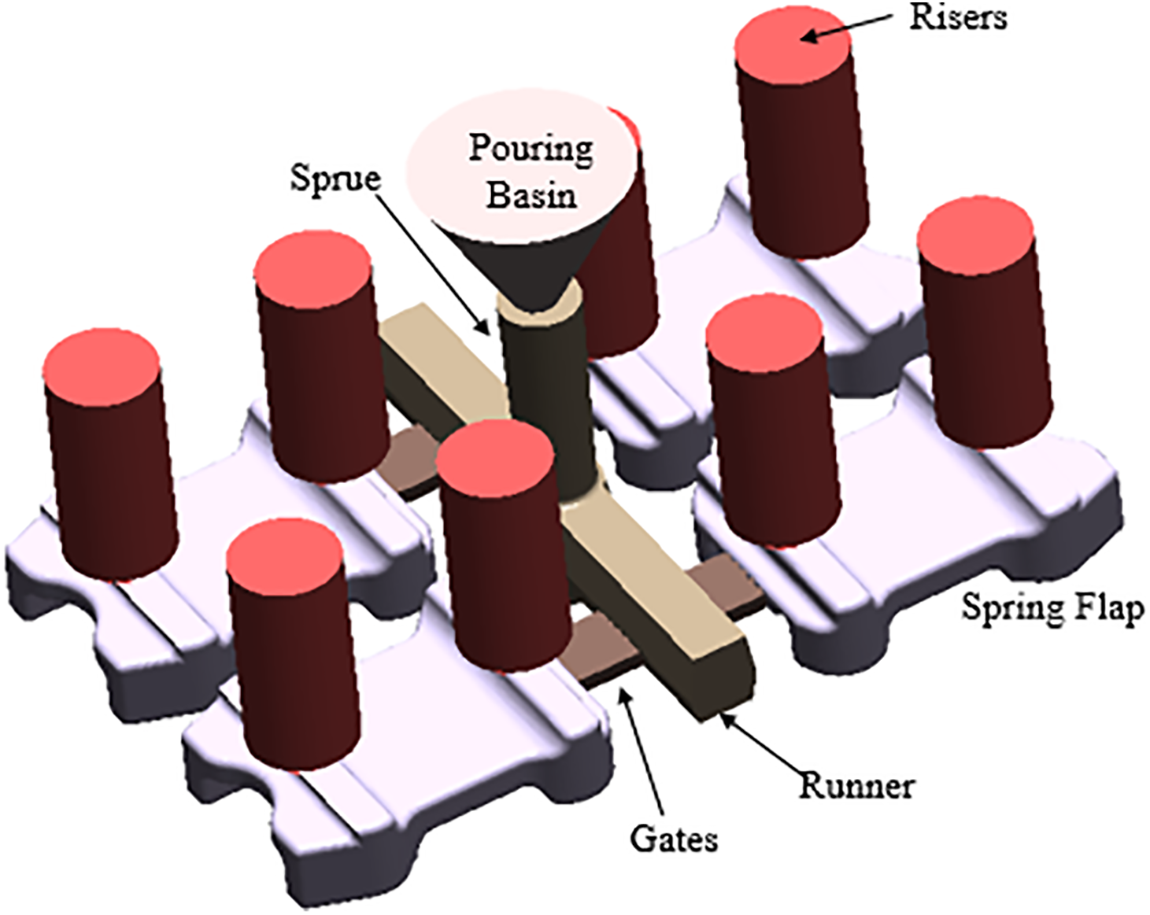
Figure 8: Initial casting layout for spring flap
Figs. 9 to 12 show the simulation results for the initial mold design. The temperature profile with the progress of solidification is presented in Fig. 9. It is evident that thin sections solidified which is also confirmed by a percentage of solid fraction shown in Fig. 10. Except for the thickest section, the majority of the flap is found solidified at 75% solidification. Fig. 11 shows that residual stresses are much higher, at 182 MPa. Furthermore, these stresses were found to be centered in the load-carrying region of the flap, indicating the need to optimize the cooling and solidification sequence within the mold.
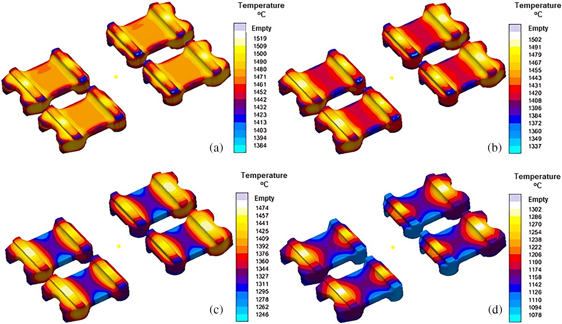
Figure 9: Temperature distribution within the mold during various stages of solidification (a) 25%, (b) 50%, (c) 75% and (d) 100%
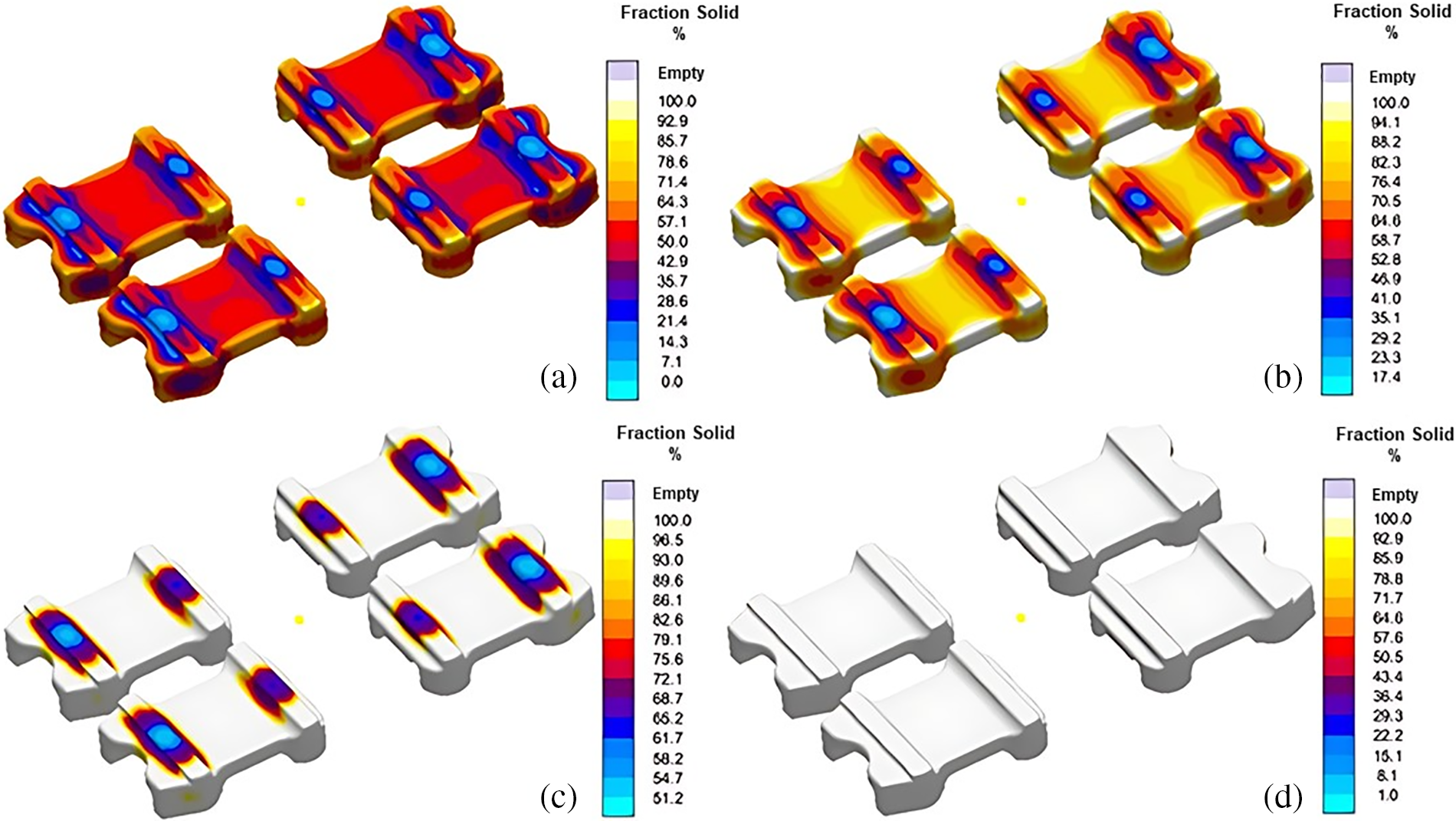
Figure 10: Solidification pattern at different solidification stages (a) 25%, (b) 50%, (c) 75% and (d) 100%
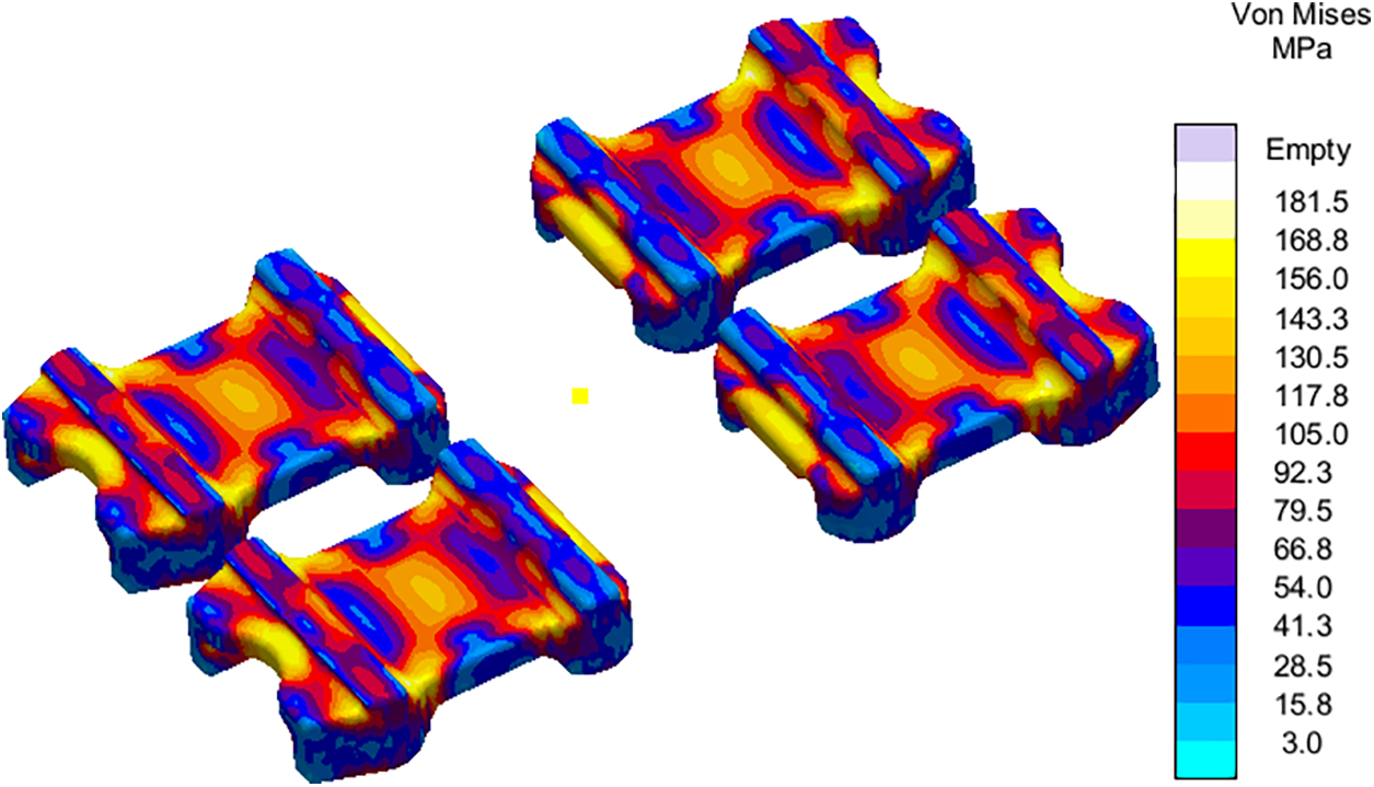
Figure 11: Residual stress distribution at the end of solidification for initial mold design
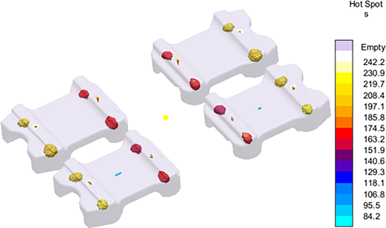
Figure 12: Prediction of Hotspots formation in cast part during initial mold design
The defects predicted by the software are hotspots and porosities. Fig. 12 shows the hotspots which need to be minimized/eliminated to evade shrinkage porosities. Porosity predictions are shown in Fig. 13. Surface and microporosities are shown in Fig. 13a and b, respectively. While surface porosity is found at specific locations on the flap, the microporosities are found to be distributed over the entire flap volume. Besides surface porosity, some internal porosity is also observed as shown in the cut-plane view of the results in Fig. 13c. Hence, the mold design had to be optimized for residual stress and defect minimization in the spring flaps.

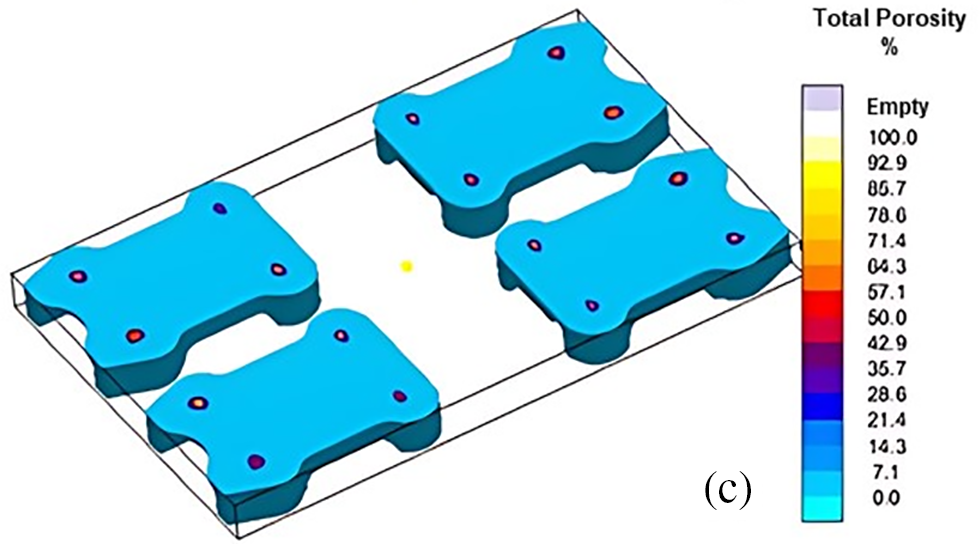
Figure 13: Porosity predictions during initial model design. (a) Porosity, (b) Microporosity, and (c) Total porosity
The mold design is optimized based on findings presented in Section 3.1. It started with the addition of chills for better cooling and directional solidification. Four chills are used per flap as shown in Fig. 14 with an aim to solidify thick sections of the flaps followed by thin sections. It is expected to reduce the residual stresses via improved cooling in the mold. Exothermic sleeves are used to treat the hotspots surrounding the riser so that solidification can be delayed, resulting in little to no shrinkage porosity in the finished castings. Breaker cores are inserted to help with the rapid removal of risers during post-casting cleaning and finishing operations as well as to prevent the riser necks from freezing too early. Fig. 14 displays the entire mold design with the addition of auxiliary components for optimization. Once again, this casting layout is discretized and resulted in 2,011,764 volume elements. Pouring time and temperature, and room temperature remained the same. With these inputs, the modified mold design is simulated to observe its effect on filling and solidification behavior, stress generation and distribution, and defect prediction.
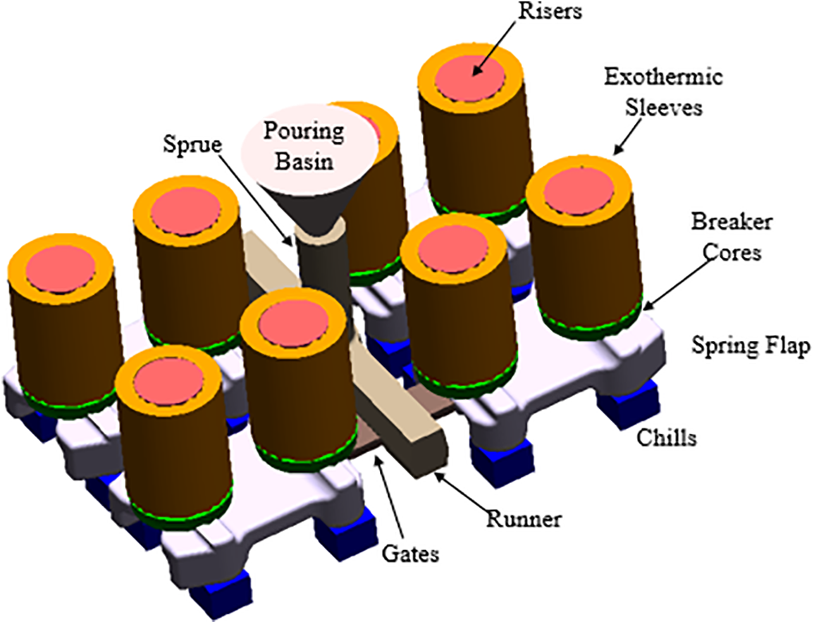
Figure 14: Design layout of optimized casting
Figs. 15 to 19 show the simulation results for optimized mold design. The areas closed to chills experienced minimum temperature as shown in Fig. 15a–d. Hence, cooling and solidification is expected to begin from this area of flaps. Moreover, it is confirmed through the solidification sequence presented in Fig. 16 that the regions closed to chill are solidified first. Significant reduction (about 3 times) are observed in the residual stresses using the new mold design as shown in Fig. 17. In addition to this, load-carrying regions are found to experience minimum residual stresses. Fig. 18 depicts the complete elimination of hotspots in the spring flaps as a result of using exothermic sleeves and breaker cores. This also helped in porosity minimization as shown in Fig. 19a where flaps are found with no surface porosities. The magnitude of microporosity is also reduced as shown in Fig. 19b. Fig. 19c shows traces of porosity, but the level is acceptable to deem this mold design adequate for casting the spring flaps despite the presence of some porosity.
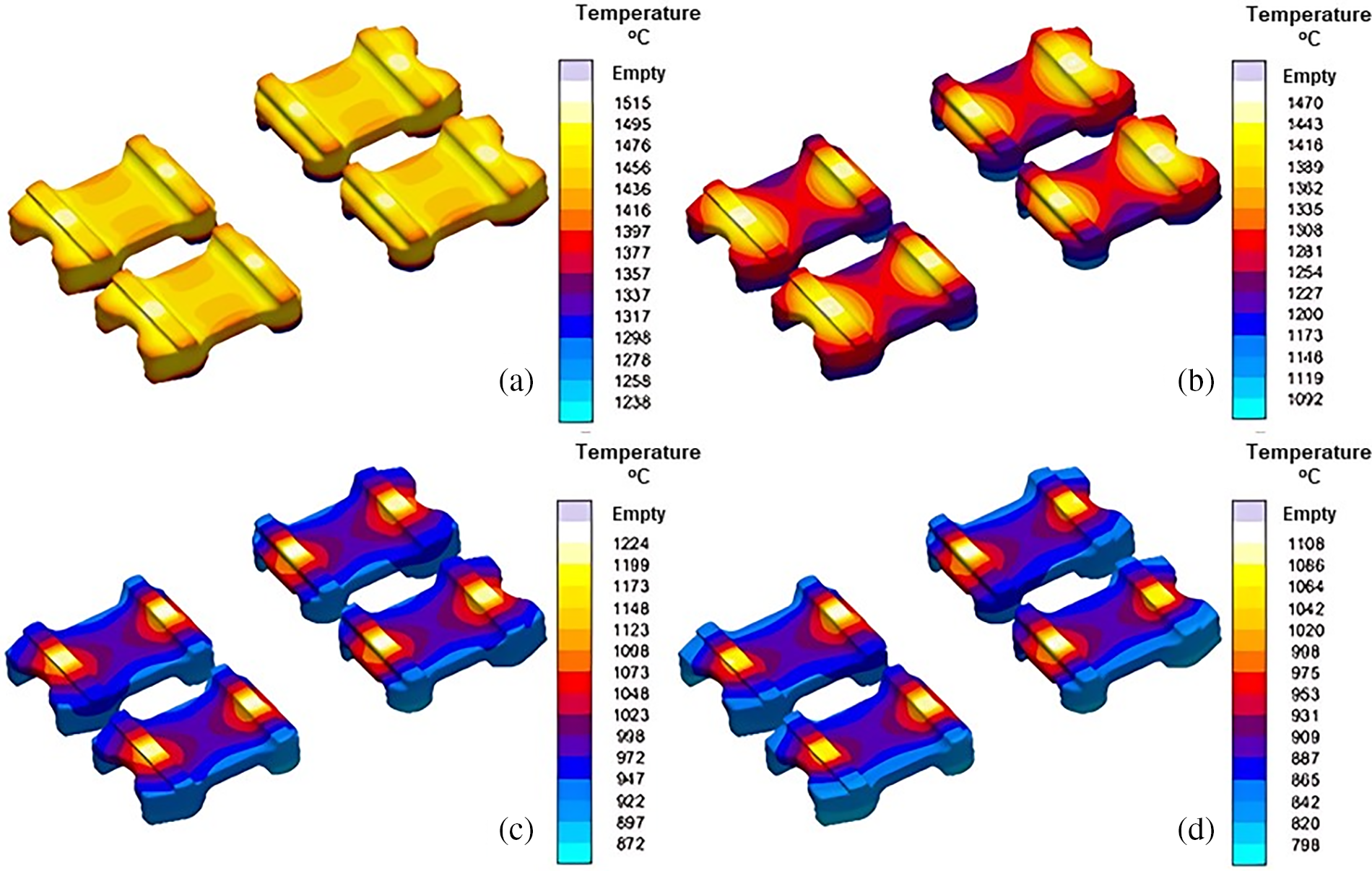
Figure 15: Temperature distribution in the mold during various stages of solidification (a) 25%, (b) 50%, (c) 75% and (d) 100%
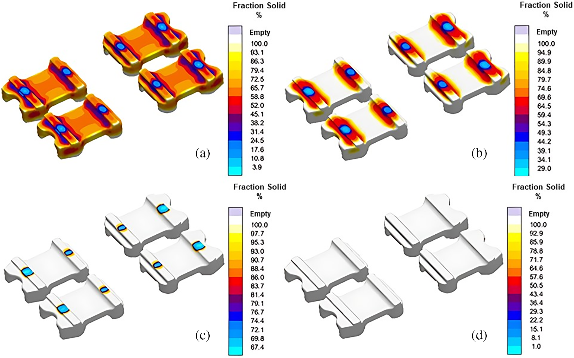
Figure 16: Solidification sequence (a) 25%, (b) 50%, (c) 75% and (d) 100%
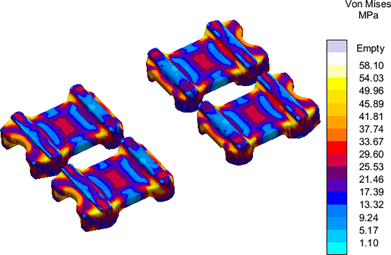
Figure 17: Distribution of residual stress at removal utilizing an improved mold design
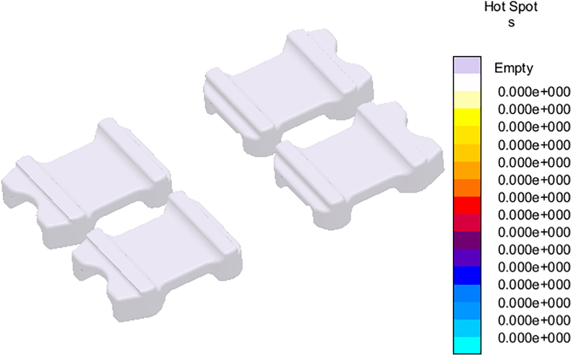
Figure 18: Cast spring flap hotspots using an optimized mold design
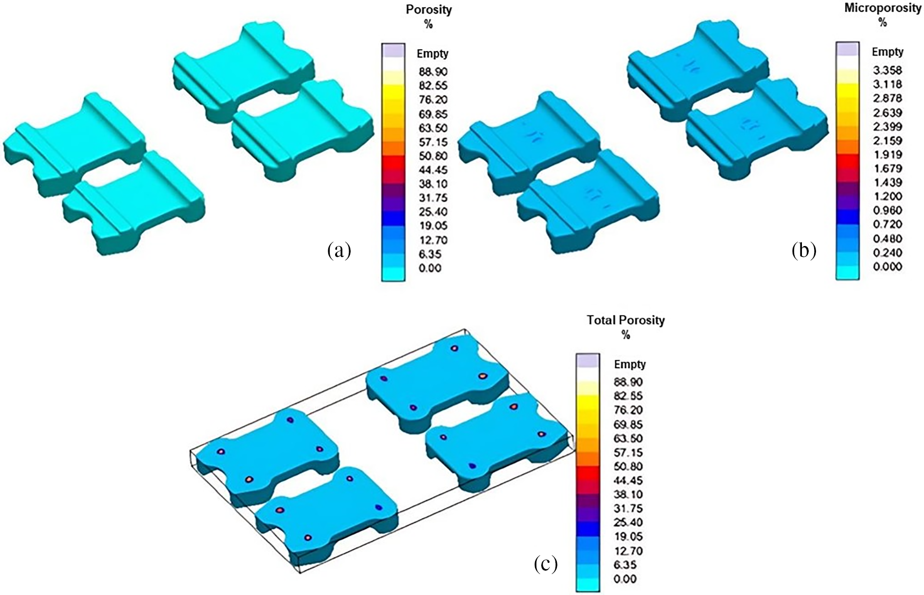
Figure 19: (a) Porosity, (b) Microporosity, and (c) Total porosity predictions using optimized mold design
4.2 Simulation-Based Fatigue Life Prediction Coupled with Optimized Mold Design
ABAQUS is used to model the spring flap using finite elements. Since a multi-cavity mold is produced and optimized to cast spring flap, it is chosen to use one spring flap for FE analysis and subsequent life prediction. Each spring flap in the optimized mold design includes a small amount of porosity, which must be considered in the FE analysis. The optimized mold design’s estimated porosity is added to the FE simulation using MAGMAlink. As illustrated in Fig. 20, the spring flap shape is imported into ABAQUS and discretized using 10-node quadratic tetrahedron (C3D10) components. The final mesh consists of 54,915 elements (with 6 mm spacing) and 82,832 nodes are used. A mesh convergence test has been performed and it is found that further mesh convergence refining did not significantly alter the results. The projected porosity is then mapped to FEA nodes on the mesh after it has been imported into MAGMASoft using MAGMAlink. The same steps outlined in [32] is then used to export and integrate the nodal porosity into ABAQUS simulations. Then, in order to accurately represent the characteristics of a spring flap in use, the boundary conditions for FE simulations are carefully selected. Based on the data that obtained from the end-user, the boundary conditions are established. As was previously mentioned, the flap is a component of a suspension system that receives a load of about 70 kN when an axle lies on it. The end-user-provided 90 kN as the maximum load that can be applied to the flap. A fully-constrained boundary condition is used to secure the thick section of the flap, while the surface where the flap and axle make contact is uniformly loaded. Boundary conditions for FE simulations are represented in Fig. 20.
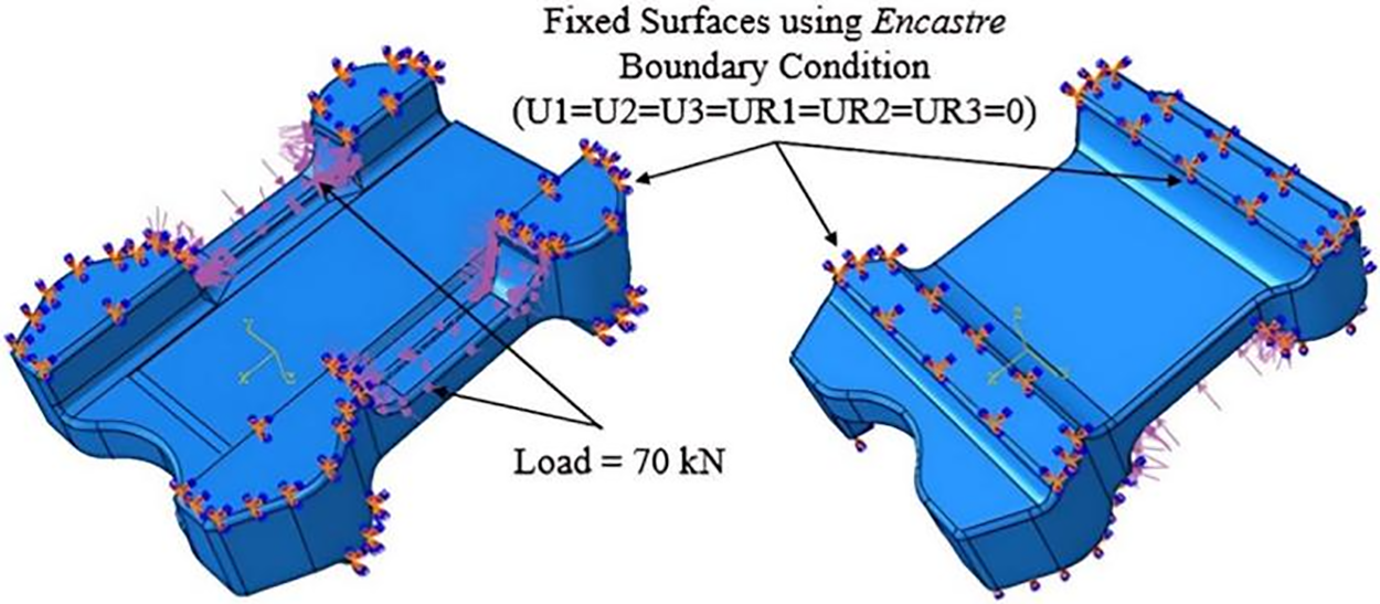
Figure 20: Boundary conditions for FE simulation of spring flap
The Von Mises stress estimates for the spring flap under the specified boundary conditions are shown in Fig. 21. Fig. 21 shows the stress field without porosity, also known as the sound defect-free spring flap (a). According to estimates, the maximum load-induced stress in this situation is around 80 MPa, which results in steel having a safety factor of 4.4 and a yield strength of 355 MPa. The load-induced stress rises to 96 MPa in the presence of porosity, resulting in a safety factor of 3.7. Fig. 21a and b both displays the location of the greatest Von Mises stress (b). A safety factor of 1.5 is found corresponding to the maximum stress with a fatigue endurance limit of 141 MPa. This factor of safety is deterministic, meaning that there is no variability in the strength of the material or the load-induced stress. As stated earlier, a probabilistic approach will be employed in this case to assess the spring flap’s reliability.
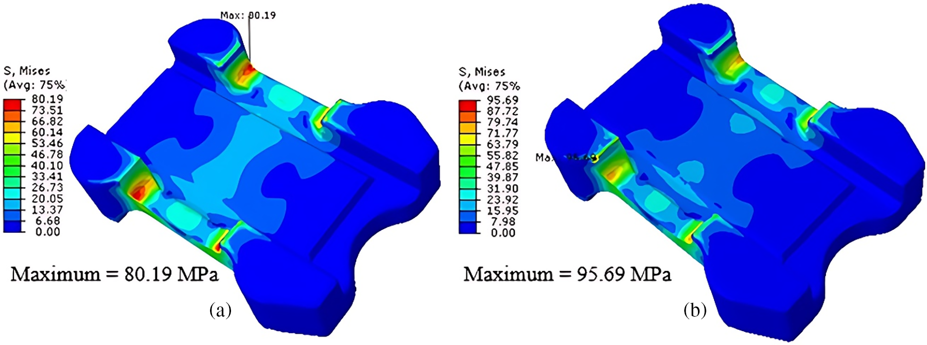
Figure 21: Von Mises stress results in spring flap (a) without porosity and (b) with porosity
The prediction of the fatigue life with and without porosity is the next step in the investigation. If the porosity reduces the fatigue life below 106 cycles, which is set as the runout criterion in the current study, that is cause for concern. Using Fe-safe and the technique described in Section 3.3, fatigue life is predicted. Fig. 22a and b shows the findings of the fatigue life prediction (b). More than 106 cycles are found to be the minimal fatigue life with and without porosity, which shows that the part will survive under these assumptions. These results so confirm the reliability of the spring flap mold design that was improved.
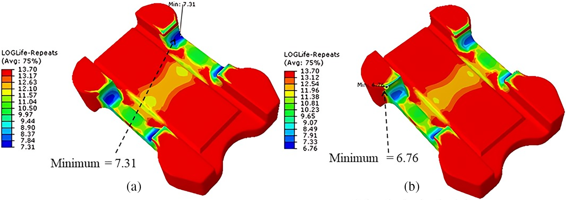
Figure 22: Prediction of Fatigue life using Fe-safe (a) without porosity and (b) with porosity
The reliability of the spring flap at a given target life is evaluated using the strength-stress interference technique. As the normal load on the flap is 70 kN and the maximum load capacity provided by the end user is 90 kN, two load-induced stresses are used in the calculations. To model stresses under these two loading conditions, the flap with porosity is used. Fig. 23 illustrates the stress fields that resulted. Then, in Fe-safe, these stresses are used to reliability predictions. The material variability is represented by a Weibull distribution with a variable shape parameter β, with a 5% variability in load-induced stresses considered.
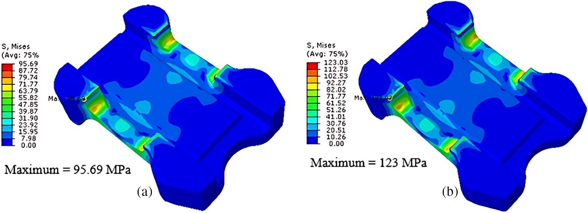
Figure 23: Von Mises stress in spring flap with porosity at (a) 70 kN and (b) 90 kN
Fig. 24 shows the resulting reliability curves for both situations. The reliability results for a load of 70 kN on a spring flap generating a load-induced stress of 96 MPa are shown in Fig. 24a. It is evident that the component demonstrates reliability of over 95% up to 106 cycles with β = 10. This higher value reflects the actual situation in which the parts are made utilizing an optimized mold with reduced porosity and product variability. Reliability predictions using a lower β, such as 3 or 4, would occur if the parts are not made using an optimal mold. In that situation, 60%–70% of the parts make it to the point of infinite life. The reliability is seriously impacted by a maximum load of 90 kN and the resulting load-induced stress of 123 MPa. Fig. 24b shows that even a higher value of β = 10 produced 65% of components that survive till the infinite life.
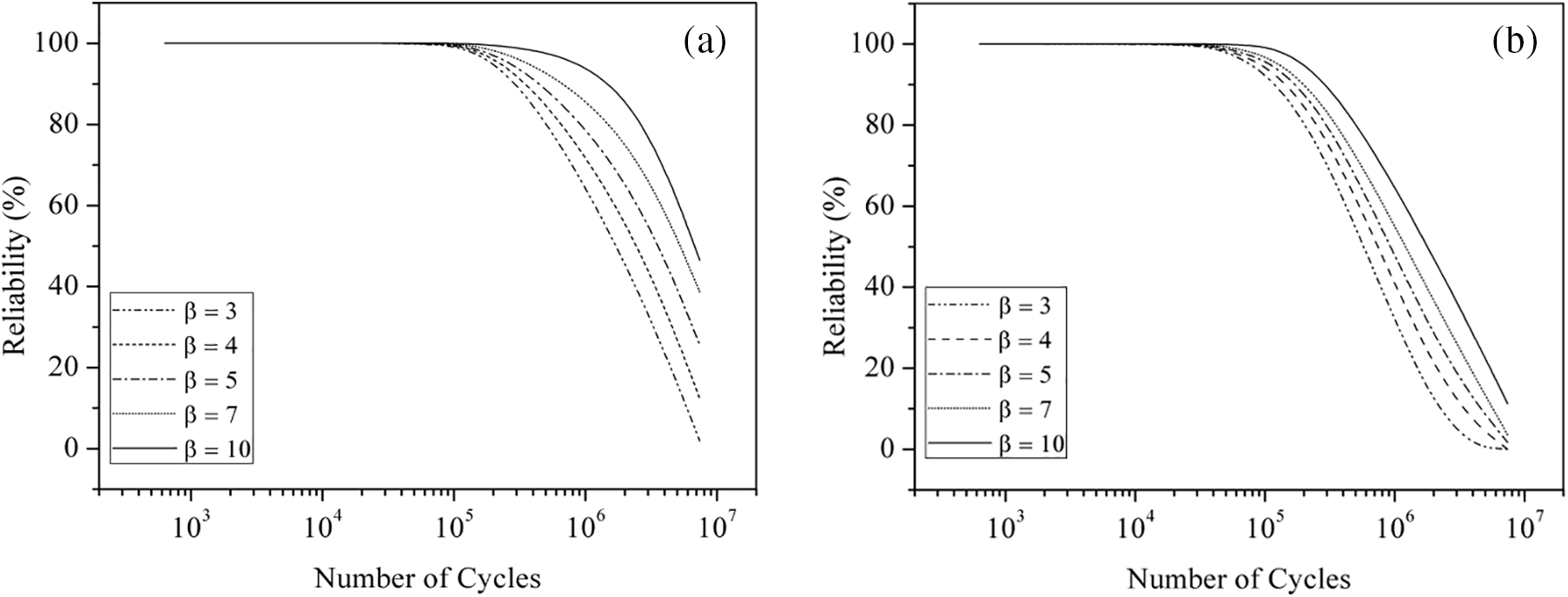
Figure 24: Reliability estimated with a load-induced stress of (a) 96 MPa and (b) 123 MPa on spring flap
An integration of casting simulation with fatigue life and reliability simulations is used in this study for a steel spring flap. Mold design optimization towards porosity minimization is done using MAGMASoft and then porosity predictions are incorporated to life prediction and reliability assessment in ABAQUS and Fe-safe, respectively. The following conclusions can be drawn from the results:
• Predictions of fatigue life under normal and maximum load conditions were promising, indicating an expected life of more than 106 cycles (infinite life) for each instance.
• Under typical loading conditions, it was found that 95% of steel spring flaps could achieve an infinite life. However, under maximum stress conditions, the reliability of the spring flaps was significantly compromised.
• The findings suggest that switching from forged to cast spring flaps is a promising option.
• Further improvements in casting design to achieve practically negligible porosity could result in 100% reliability under typical loading conditions of 70 kN in automotive suspension systems.
• Under maximum loading conditions, the reliability measurement declined to 65%.
• Based on the reliability results obtained, safe load-induced stress on the spring flap could be 95 MPa.
Autonomous optimization of the mold can be done in the future to minimize multiple casting defects simultaneously. A holistic approach is to integrate casting simulations, mechanical performance simulations, and reliability simulations to perform a cradle-to-grave analysis in a completely virtual domain. This can be done by developing a comprehensive tool capable of integrating all simulations, and data acquisition for loading and failure of cast parts. Even though this integration and data collection is challenging, it can lead to numerous advantages for foundries, some of which are cost and time savings, robust mold designs, high-quality castings, and minimum risks associated with casting failures.
Acknowledgement: The authors would like to acknowledge the support of Interdisciplinary Research Center for Intelligent Manufacturing and Robotics at King Fahd University of Petroleum and Minerals (KFUPM), Dhahran, for funding this work through Project # INMR2107. The authors appreciate the support from MAGMA to conduct this research work. M. A. Khan and M. Asad are thankful to Prince Mohammad Bin Fahd University for providing a supportive environment in publishing this work.
Funding Statement: This work is funded by Interdisciplinary Research Center for Intelligent Manufacturing and Robotics at King Fahd University of Petroleum and Minerals (KFUPM), Dhahran, through Project # INMR2107.
Author Contributions: Muhammad Azhar Ali Khan: Conceptualization, Methodology, Software, Experiments, Data Curation, Writing—Original Draft Preparation. Syed Sohail Akhtar: Conceptualization, Visualization, Software, Writing—Reviewing and Editing. Abba A. Abubakar: Writing, Investigation, Software. Muhammad Asad: Software, Writing—Reviewing and Editing. Khaled S. Al-Athel: Writing, Investigation, Reviewing and Editing. All authors reviewed the results and approved the final version of the manuscript.
Availability of Data and Materials: Data will be made available on reasonable request.
Ethics Approval: No applicable.
Conflicts of Interest: The authors declare that they have no conflicts of interest to report regarding the present study.
References
1. Lehmhus D. Advances in metal casting technology: a review of state of the art, challenges and trends—part I: changing markets, changing products. Metals. 2022 Nov;12(11):1959. doi:10.3390/met12111959. [Google Scholar] [CrossRef]
2. Roy K, James BPL, Yousefi AM, Clifton GC, Mahendran M. Low fatigue response of crest-fixed cold-formed steel drape curved roof claddings. In: CCFSS Proceedings of International Specialty Conference on Cold-Formed Steel Structures, 2018; Rolla, MO, USA: Missouri University of Science and Technology. p. 1971–2018. [Google Scholar]
3. Feng R, Yang F, Shao Y, Roy K, Lim J, Chen B. Experimental study on high-cycle fatigue behaviour of butt welds made of corroded AISI 304 stainless steel and Q460 high-strength steel. Structures. 2024 Apr;62:106141. doi:10.1016/j.istruc.2024.106141. [Google Scholar] [CrossRef]
4. Shiraiwa T, Briffod F, Enoki M. Development of integrated framework for fatigue life prediction in welded structures. Eng Fract Mech. 2018 Jul;198:158–70. doi:10.1016/j.engfracmech.2017.11.012. [Google Scholar] [CrossRef]
5. Khan MAA, Sheikh AK, Asad M. Mold design and casting of an impeller using MAGMASoft. Int J Mech Eng Robot Res. 2020;9(12):1579–83. [Google Scholar]
6. Sheikh AK, Khan MAA, Iqbal H, Al-Shaer BS. Casting of adjuster bracket—process optimization and validation. Mater Manuf Process. 2018 Dec 10;33(16):1845–50. doi:10.1080/10426914.2018.1476769. [Google Scholar] [CrossRef]
7. Bhatt H, Barot R, Bhatt K, Beravala H, Shah J. Design optimization of feeding system and solidification simulation for cast iron. Procedia Technol. 2014;14:357–64. doi:10.1016/j.protcy.2014.08.046. [Google Scholar] [CrossRef]
8. Kermanpur A, Mahmoudi S, Hajipour A. Numerical simulation of metal flow and solidification in the multi-cavity casting moulds of automotive components. J Mater Process Technol. 2008 Sep;206(1–3):62–8. doi:10.1016/j.jmatprotec.2007.12.004. [Google Scholar] [CrossRef]
9. Mi G-F, Liu X-Y, Wang K-F, Fu H-Z. Application of numerical simulation technique to casting process of valve block. J Iron Steel Res Int. 2009 Apr 1;16(4):12–7. doi:10.1016/S1006-706X(09)60053-4. [Google Scholar] [CrossRef]
10. Khade US, Sawant SM. Gating design modification using 3D CAD modeling and casting simulation for improving the casting yield. Int J Adv Mech Eng. 2014;4(7):813–20. [Google Scholar]
11. Choudhari CM, Narkhede BE, Mahajan SK. Casting design and simulation of cover plate using AutoCAST-X software for defect minimization with experimental validation. Procedia Mater Sci. 2014;6(4):786–97. doi:10.1016/j.mspro.2014.07.095. [Google Scholar] [CrossRef]
12. Midea AC, Burns W, Schneider M, Wagner I. Advanced thermo-physical data for casting process simulation the importance of accurate sleeve properties. Giessereiforschung. 2007;59(1):34–43. [Google Scholar]
13. Hahn I, Hepp E. Improved ingot casting by using numerical simulation. In: ICRF 2012-First International Conference on Ingot Casting, Forging and Rolling 2012 (ICRF 2012), 2012 Jun 3–7; Aachen, Germany. [Google Scholar]
14. Rajkumar I, Rajini N, Alavudeen A, Ram Prabhu T, Ismail SO, Mohammad F, et al. Experimental and simulation analysis on multi-gate variants in sand casting process. J Manuf Process. 2021 Feb;62(2):119–31. doi:10.1016/j.jmapro.2020.12.006. [Google Scholar] [CrossRef]
15. Ayar MS, Ayar VS, George PM. Simulation and experimental validation for defect reduction in geometry varied aluminium plates casted using sand casting. Mater Today: Proc. 2020;27(6):1422–30. doi:10.1016/j.matpr.2020.02.788. [Google Scholar] [CrossRef]
16. Patil MA, Patil SD, Yadav PH, Desai AA. Methoding and defect minimization of center plate casting by auto-CASTX1 software. Mater Today: Proc. 2023;77(3):662–72. doi:10.1016/j.matpr.2022.11.286. [Google Scholar] [CrossRef]
17. Hodbe GA, Shinde BR. Design and simulation Of LM 25 sand casting for defect minimization. Mater Today Proc. 2018;5(2):4489–97. doi:10.1016/j.matpr.2017.12.018. [Google Scholar] [CrossRef]
18. Tadele Bekele B, Bhaskaran J, Dufera Tolcha S, Gelaw M. Simulation and experimental analysis of re-design the faulty position of the riser to minimize shrinkage porosity defect in sand cast sprocket gear. Mater Today: Proc. 2022;59:598–604. [Google Scholar]
19. Qiao L, Ramanujan RV, Zhu J. Optimized hot working parameters of Fe2.5Ni2.5CrAl multi-principal element alloys. J Alloys Compd. 2022 Dec;925:166594. doi:10.1016/j.jallcom.2022.166594. [Google Scholar] [CrossRef]
20. Qiao L, Zhu J. Unveiling the compressive behavior of Fe2Ni2CrAl high entropy alloy: a combined molecular dynamics and finite element study. Mater Today Commun. 2023 Mar;34:105296. doi:10.1016/j.mtcomm.2022.105296. [Google Scholar] [CrossRef]
21. Hardin RA, Beckermann C. Prediction of the fatigue life of cast steel containing shrinkage porosity. Metallurgical Mater Trans A. 2009 Mar 21;40(3):581–97. doi:10.1007/s11661-008-9755-3. [Google Scholar] [CrossRef]
22. Hardin RA, Beckermann C. Integrated design of castings: effect of porosity on mechanical performance; IOP Conf Ser Mater Sci Eng. 2012 Jul 3; 33:012069. [Google Scholar]
23. Sheikh AK, Khan MAA. Fatigue life prediction and reliability assessment of ductile iron castings using optimized mold design. Int J Adv Manuf Technol. 2020 Jan 14;106(5–6):1945–66. [Google Scholar]
24. Khan MAA, Sheikh AK, Gasem ZM, Asad M. Fatigue life and reliability of steel castings through integrated simulations and experiments. Metals. 2022 Feb 15;12(2):339. doi:10.3390/met12020339. [Google Scholar] [CrossRef]
25. Foglio E, Gelfi M, Pola A, Goffelli S, Lusuardi D. Fatigue characterization and optimization of the production process of heavy section ductile iron castings. Int J Metalcasting. 2017 Jan 21;11(1):33–43. doi:10.1007/s40962-016-0112-9. [Google Scholar] [CrossRef]
26. Ferro P, Lazzarin P, Berto F. Fatigue properties of ductile cast iron containing chunky graphite. Mater Sci Eng: A. 2012 Sep;554:122–8. doi:10.1016/j.msea.2012.06.024. [Google Scholar] [CrossRef]
27. Azeez ST, Mashinini PM. Reliability and properties enhancement of as-cast aluminum alloy through gating system design. Mater Today: Proc. 2022;62:3051–7. doi:10.1016/j.matpr.2022.03.218. [Google Scholar] [CrossRef]
28. Chaudhari A, Vasudevan H. Reliability based design optimization of casting process parameters using Markov chain model. Mater Today: Proc. 2022;63(11–12):602–6. doi:10.1016/j.matpr.2022.04.189. [Google Scholar] [CrossRef]
29. Khan MAA, Sheikh AK. Simulation-based mould design, life prediction and reliability assessment of a valve body. Int J Simul Model. 2021 Jun 15;20(2):219–30. doi:10.2507/IJSIMM. [Google Scholar] [CrossRef]
30. Dassault Systemes UK Ltd. ABAQUS users manual; 2015. Available from: https://www.3ds.com/products/simulia/abaqus.[Accessed 2024]. [Google Scholar]
31. Dassault Systemes UK Ltd. Fe-safe user manual, dassault systemes; 2015. Available from: https://www.3ds.com/products/simulia/fe-safe.[Accessed 2024]. [Google Scholar]
32. Sheikh AK, Khan MAA. Mold design optimization and quality assessment of steel castings through integrated simulations and experiments. J Mech Sci Technol. 2020 Jul 8;34(7):2975–83. doi:10.1007/s12206-020-0629-y. [Google Scholar] [CrossRef]
33. MAGMASOFT. 2023.Available from: https://www.magmasoft.com/en/solutions/magmasoft/. [Accessed 2024]. [Google Scholar]
34. Tvergaard V. Influence of voids on shear band instabilities under plane strain conditions. Int J Fract. 1981 Aug;17(4):389–407. doi:10.1007/BF00036191. [Google Scholar] [CrossRef]
35. Gurson AL. Continuum theory of ductile rupture by void nucleation and growth: part I—yield criteria and flow rules for porous ductile media. J Eng Mater Technol. 1977 Jan 1;99(1):2–15. doi:10.1115/1.3443401. [Google Scholar] [CrossRef]
36. Needleman A, Tvergaard V. An analysis of ductile rupture in notched bars. J Mech Phys Solids. 1984 Jan;32(6):461–90. doi:10.1016/0022-5096(84)90031-0. [Google Scholar] [CrossRef]
37. Aravas N. On the numerical integration of a class of pressure-dependent plasticity models. Int J Numer Methods Eng. 1987 Jul 23;24(7):1395–416. doi:10.1002/nme.1620240713. [Google Scholar] [CrossRef]
38. Spitzig WA. Effect of hydrostatic pressure on deformation, damage evolution, and fracture of iron with various initial porosities. Acta Metallurgica Mater. 1990 Aug;38(8):1445–53. doi:10.1016/0956-7151(90)90113-U. [Google Scholar] [CrossRef]
39. Samar Ali S, Kannan S. A diagnostic approach to Weibull-Weibull stress-strength model and its generalization. Int J Qual Reliab Manage. 2011 Apr 19;28(4):451–63. doi:10.1108/02656711111121834. [Google Scholar] [CrossRef]
40. Feeding & Risering Guidelines for Steel Castings. 2001. Available from: https://old.foundrygate.com/upload/artigos/uCBMgMBZZRDCQXtWWCxk4oFtcPT7.pdf. [Accessed 2024]. [Google Scholar]
Cite This Article
 Copyright © 2024 The Author(s). Published by Tech Science Press.
This work is licensed under a Creative Commons Attribution 4.0 International License , which permits unrestricted use, distribution, and reproduction in any medium, provided the original work is properly cited.


 Submit a Paper
 Propose a Special lssue
 View Full Text
 Download PDF
 Downloads
 Citation Tools