
 Submit a Paper
 Propose a Special lssue
 Open Access
ARTICLE
Precision Motion Control of Hydraulic Actuator Using Adaptive Back-Stepping Sliding Mode Controller
1 Henan Key Laboratory of Superhard Abrasives and Grinding Equipment, Henan University of Technology, Zhengzhou, 450001, China
2 School of Mechanical and Electrical Engineering, Henan University of Technology, Zhengzhou, 450001, China
* Corresponding Author: Zhenshuai Wan. Email:
Computer Modeling in Engineering & Sciences 2024, 141(2), 1047-1065. https://doi.org/10.32604/cmes.2024.053773
Received 10 May 2024; Accepted 15 August 2024; Issue published 27 September 2024
 View Full Text
 Download PDF
Abstract
Hydraulic actuators are highly nonlinear when they are subjected to different types of model uncertainties and dynamic disturbances. These unfavorable factors adversely affect the control performance of the hydraulic actuator. Although various control methods have been employed to improve the tracking precision of the dynamic system, optimizing and adjusting control gain to mitigate the hydraulic actuator model uncertainties remains elusive. This study presents an adaptive back-stepping sliding mode controller (ABSMC) to enhance the trajectory tracking precision, where the virtual control law is constructed to replace the position error. The adaptive control theory is introduced in back-stepping controller design to compensate for the model uncertainties and time-varying disturbances. Based on Lyapunov theory, the finite-time convergence of the position tracking errors is proved. Furthermore, the effectiveness of the developed control scheme is conducted via extensive comparative experiments.Keywords
In virtues of fast response, high power-to-weight ratio, as well as larger driving force, hydraulic actuators have been widely used in many equipment [1], e.g., robotic actuators, rolling machines, and load simulators, in which good dynamic response and high accuracy tracking performance are crucial [2–5]. Meanwhile, various model uncertainties and dynamic disturbances such as frictions, unknown payloads, backlash, and unmodeled dynamics widely exist in hydraulic actuators, adversely affecting their control performance [6–9]. Due to the increasing interest in high-precision control, reducing the influence of external load disturbance and parameter change is a key goal for hydraulic servo system controller design.
So as to retain the satisfactory control performance of hydraulic actuators, several progressive control methods have been developed, such as adaptive control [10–12], robust control [13–16], back-stepping control [17–20] and sliding mode control (SMC) [21–24]. Adaptive control can reach a good position by tracking the controller under parameter uncertainties utilizing the online learning control law. However, the parameter convergence of the adaptive law can only be realized under continuous excitation, which is too stringent to be satisfied in practice. Guo et al. [25] proposed an adaptive controller with improved parameter convergence to achieve the high-performance trajectory tracking control of a hydraulic servo system, where the composite learning scheme is driven by both tracking and prediction error. Back-stepping control has been successfully utilized to deal with the nonlinear system. Then, Guo et al. [26] proposed a back-stepping control scheme with an extended-state-observer (ESO) to handle the load disturbance and uncertain nonlinearity of the electro-hydraulic system, where the ESO is presented to estimate the external disturbance and modeling uncertainty. In order to solve the discontinuity problem of traditional SMC, the continuous saturation function rather than the discontinuous sign function is adopted in the controller design procedure [27–29]. Although the tracking error of the abovementioned can be guaranteed to be bounded, the asymptotic tracking performance is lost. The high-order SMC can obtain asymptotic tracking and controller continuity, but the controller design needs information on the derivatives of sliding mode variables [30]. However, the sliding mode variable derivative is often considered unknown in practice, so it is not easy to implement in real systems [31]. Super-twisting SMC can avoid the problems above, but the gain of the controller must be artificially set, which is conservative to some certain extent [32]. With the motivation discussed above, the adaptive back-stepping sliding mode controller (ABSMC) control scheme is proposed to deal with various modeling uncertainties and external disturbances of the hydraulic actuator. Based on the system model information, the adaptive law is added to the traditional SMC to improve the system’s servo controller precision. The main innovations of this study are summarized as follows. 1) The nonlinear model of the hydraulic actuator considering model uncertainties and dynamic disturbances is constructed. 2) The proposed control scheme improves the robustness and disturbance rejection performance by utilizing the back-stepping and SMC. 3) The faster convergence chattering suppression is validated by different work conditions under uncertainties.
The paper is structured as follows: The dynamic model is formulated in Section 2. Section 3 proposes the SMC design with adaptive control law, where the system stability analysis is also provided. Comparative studies are discussed in Section 4, where the superiority of the ABSMC is described in comparison to the other controllers. Finally, conclusions are drawn in Section 5.
2 Dynamic Model and Problem Formulation
In this section, the dynamic characteristics of the hydraulic actuator are provided, and the related control problems are formulated. Fig. 1 shows the schematic diagram of the hydraulic actuator, comprised of a double-acting hydraulic cylinder, servo valve, electric motor, relief valve, and accumulator. As a conversion device, the hydraulic pump converts the motor’s electric energy into the hydraulic energy of oil. The servo valve provides the oil pressure to the hydraulic cylinder for controlling the piston’s movement. The variable pressure of incompressible fluid hinders the precise control of the actuator. An accurate mathematical model is the first step of controller design, so the hydraulic actuator’s dynamic model is performed below.
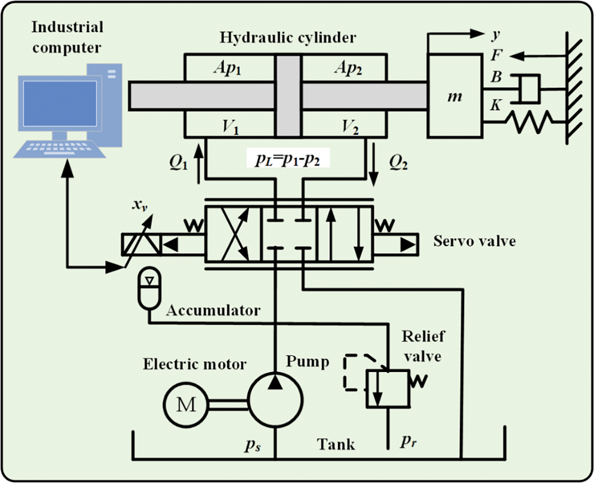
Figure 1: Scheme diagram of the hydraulic actuator
The flow pressure relation of servo valve is described as follows [33]:
where QL is load flow, Cd is discharge coefficient, w is the area gradient of the servo valve, Ps is supply pressure, PL is load pressure, and ρ is hydraulic oil density.
Because the servo valve dynamic characteristics are faster than the rest of the system, the relationship between input voltage and spool displacement is given by
where ksv is the torque motor gain, and u is the input voltage of the torque motor.
The load pressure dynamics of the hydraulic actuator are capable to be expressed as follows:
where Vt is the total control volume of the cylinder chamber, βe is the effective bulk modulus, A is the actuator ram area, and Ct is the total leakage coefficient.
Based on the Newton’s second law, the load motion can be described as follows:
where m is the load mass, B is the actuator ram area, K is the viscous damping coefficient of hydraulic oil, and f is the external load of the system.
The state variables are defined as
where
The total uncertainty F is bounded, satisfying the following condition [34]:
where
The objective of controller design is to construct an adaptive control strategy such that the cylinder displacement
3.1 Back-Stepping Sliding Mode Controller
The position tracking error and its time derivative are defined as follows:
The first Lyapunov function is defined as follows:
Define
where
Then, the virtual control law
The time derivative of the Lyapunov function V1 is given by
Clearly, if
The second Lyapunov function is defined as follows:
The time derivative of V2 is
Define
where
The virtual control law
Then Eq. (14) can be written as follows:
The sliding surface is defined as follows:
The third Lyapunov function is selected as follows:
Taking the derivative of Eq. (19) with respect to time gives
Given the dynamic system, the control law is designed as follows:
where h and β are positive constants.
Substituting Eq. (21) into Eq. (20) leads for
Selecting the matrix Q as follows:
Define
If the Q is a positive definite matrix, then
in which,
By choosing the appropriate value for h,
Based on LaSalle’s invariance principle, if
3.2 Adaptive Control Law Design
The controller mentioned above design is based on the assumption that the bound of the uncertainty F is known. Uncertainty and external disturbance are usually unknown in practical situations, so the F is difficult to determine. Given this condition, an adaptive control law is developed to estimate the F. It is assumed that the total uncertainty items change slowly then
The estimation error is derived as follows:
where
The Lyapunov function candidate is defined as follows [35]:
where γ is a positive constant.
The time derivative of V4 is
The adaptive control law is designed as follows:
Thus, the ABSMC is presented as follows:
Substituting Eq. (31) into Eq. (30) leads for
Based on the Lyapunov-Like Lemma, the hydraulic actuator is globally asymptotically stable by adopting adaptive sliding mode control law. Hence, the hydraulic actuator can accurately track the reference trajectory at the desired position. For ease of understanding of the proposed controller, its block diagram is provided as shown in Fig. 2. To ensure the robustness of the hydraulic actuator to uncertainty and interference, the sliding surface is introduced into the back-stepping control. In addition, the adaptive law is adopted to estimate the model uncertainties.
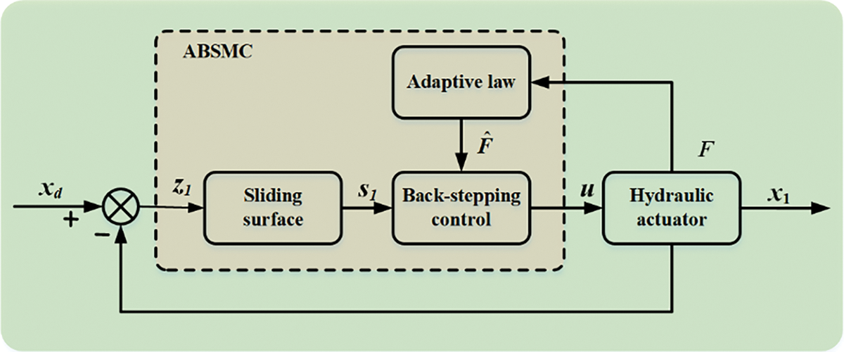
Figure 2: Block diagram of the proposed controller
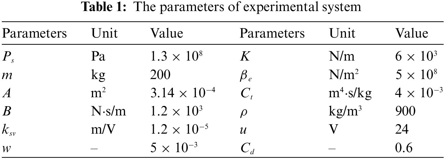
To illustrate the effectiveness of the developed control scheme, a hydraulic actuator experimental platform is set up, as shown in Fig. 3. It consists of hydraulic actuator, a servo valve whose flow rate is 75 L/min, a sensor system including position sensor and pressure, a signal conditioner working signal conversion and filtering, a control system that includes host computer as well as target computer connecting signal by TCP/IP, and a real-time control software with 16-bit A/D card well as 16-bit D/A card. The hydraulic actuator displacement is driven by a servo valve control signal, regulated by a signal conditioner. Feedback signals, including position and pressure, are collected by the A/D board in real time and sent to a computer for a closed feedback system. The sample time of experimental equipment is 1 ms. The specificparameters of the system are displayed in Table 1. In this study, three controllers are compared.
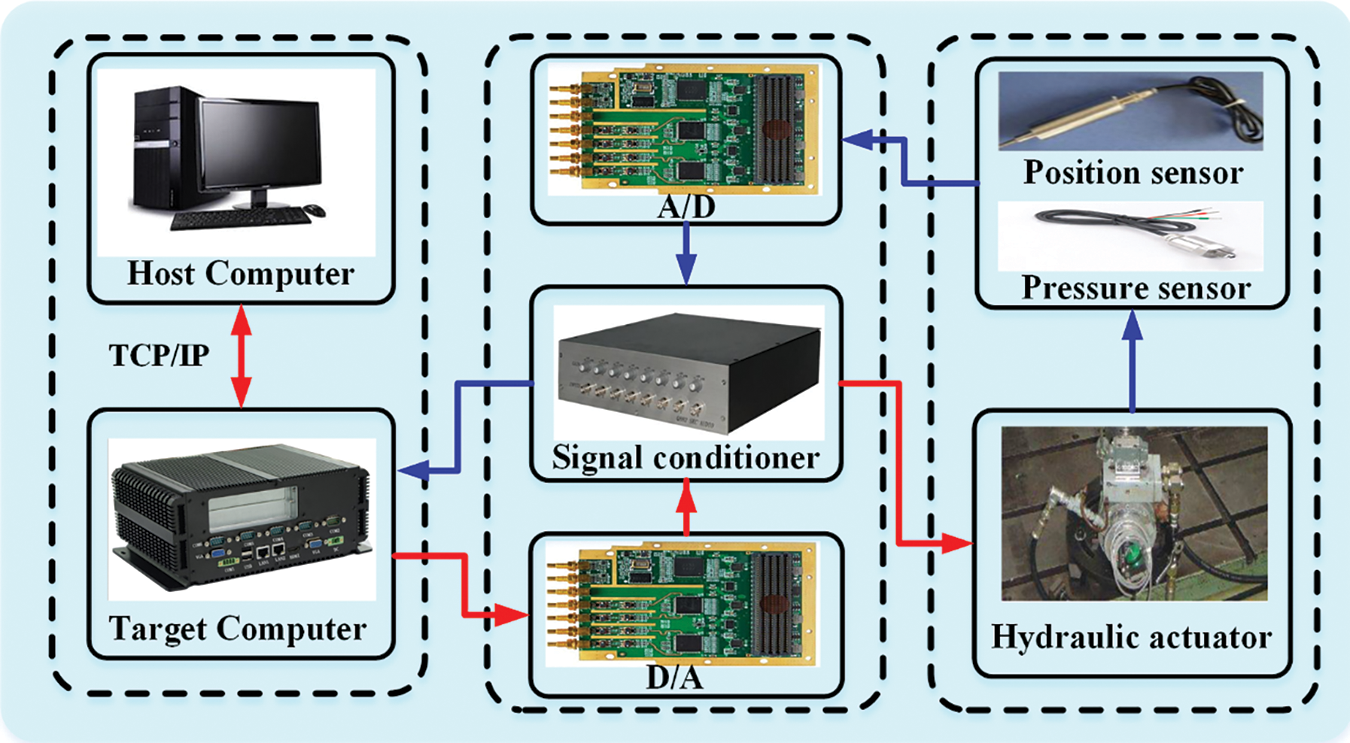
Figure 3: Experimental platform of hydraulic actuator system
ABSMC: The parameters of ABSMC are designed as h = 200, β = 0.8,
SMC: The control law is set as
PID (Proportion Integration Differentiation): The PID parameters are designed as Kp = 40, Ki = 1, and Kd = 0.2 using an intelligent optimization algorithm. The above design parameters have considered the system’s steady-state and transient performance.
The three controllers are first tested for sinusoidal motion trajectory y = 60 sin(2πt) mm. The tracking result and errors are compared in Figs. 4 and 5, respectively. The tracking trajectory nearly overlaps the desired ones, and the tracking errors are bounded and stable. Compared to PID, SMC improves the tracking precision to some extent. In addition, the tracking error of ABSMC is smaller than that of SMC. This is because the designed adaptive control law deals with the parametric uncertainties and dynamic disturbance well. The ABSMC achieves the smallest tracking error by employing the proposed control scheme, with an almost 80% reduction for the maximum tracking error. The compared control input of three controllers is shown in Fig. 6. All the control inputs are continuous and bounded, and PID produces the largest control amplitude and violently violent fluctuation. In addition, the chattering level of ABSMC is lower than that of SMC, which is essential to actuators in practice applications. The disturbance estimation and adaptive control law curve are displayed in Fig. 7, where the disturbance signal is set as y = 12 sin(2πt) mm. The unknown dynamics are estimated by the proposed estimator, and the adaptive control law tends to be stable after a short fluctuation. To further show the effectiveness of ABSMC, the sinusoidal signals with different amplitudes and frequencies are studied. The corresponding experimental results are shown in Fig. 8, which indicates that the error indices increase as the amplitude of sinusoidal trajectories increases from 75 to 90 mm. In contrast, the lower the reference signal frequency, the smaller the tracking error indices.
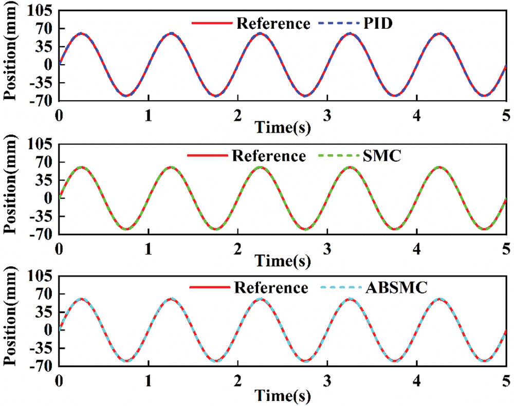
Figure 4: Tracking trajectory of sinusoidal motion
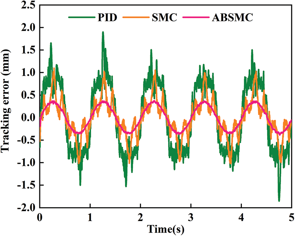
Figure 5: Tracking error of sinusoidal motion

Figure 6: Control input of sinusoidal motion
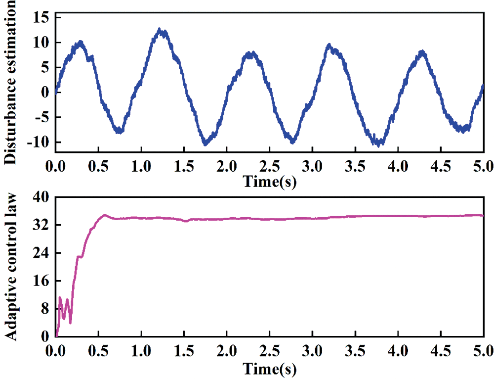
Figure 7: Disturbance of sinusoidal motion estimation and adaptive control law curve

Figure 8: Comparison of performance indices for different reference signals
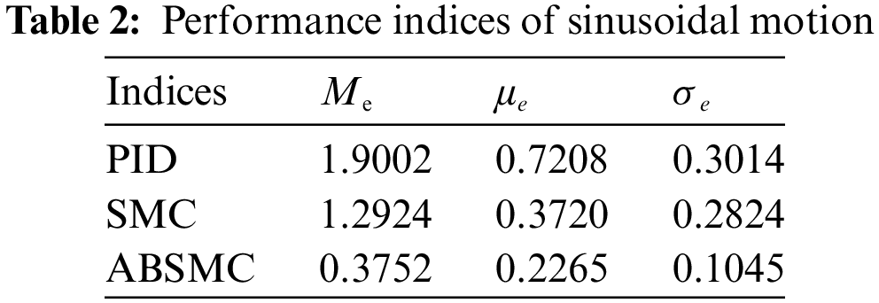
For the quantitative analysis of the control performance of different controllers, the maximum absolute error Me, the mean absolute error μe, and the average standard absolute error σe are defined as
where
The performance indices of sinusoidal motion are listed in Table 2. The proposed ABSMC gives smaller indices value than the other two controllers. The SMC produces better control performance than the PID. Compared to the other two controllers, the σe of ABSMC is the least, which means the chattering is also the least among the abovementioned three controllers. This is because the adaptive control law has less noise sensitivity. Namely, the proposed ABSMC obtains the best tracking performance.
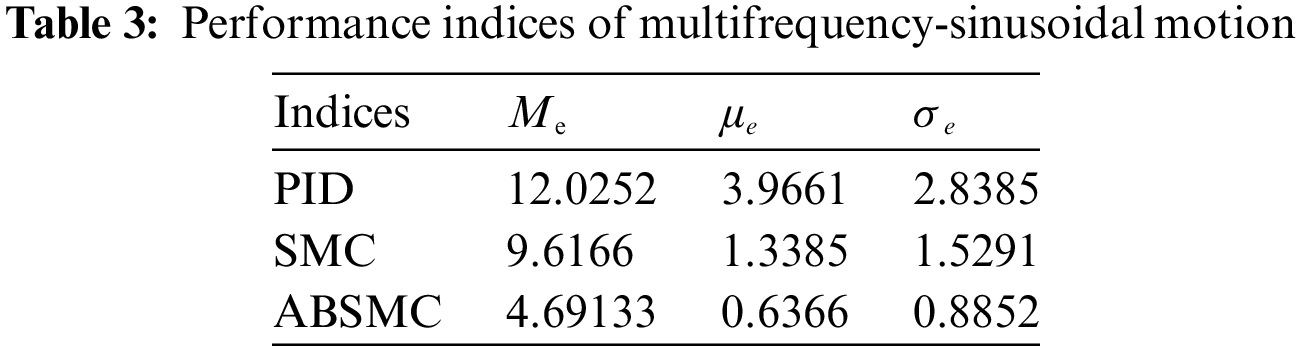
To further test the control performance of the proposed ABSMC method, a multifrequency-sinusoidal motion trajectory y = 60 sin(2πt) + 30 sin(5πt) mm is applied. The tracking trajectory and tracking error of multifrequency-sinusoidal motion are depicted in Figs. 9 and 10, respectively. One can find that the tracking performance of PID is less than that of the other two control methods. Although some chatter exists in ABSMC, the control input is reduced compared to SMC. Fig. 11 shows their comparative control input. The control input is smoother than that of SMC and PID, which helps reduce chattering and improve control performance. The performance indices of multifrequency-sinusoidal motion are collected in Table 3. The Me of the ABSMC is 12.0252 mm, smaller than that of SMC (9.6166 mm) and PID control (4.6913 mm). It indicates that the proposed ABSMC can obtain tracking accuracy at a satisfactory level.

Figure 9: Tracking trajectory of multifrequency-sinusoidal motion
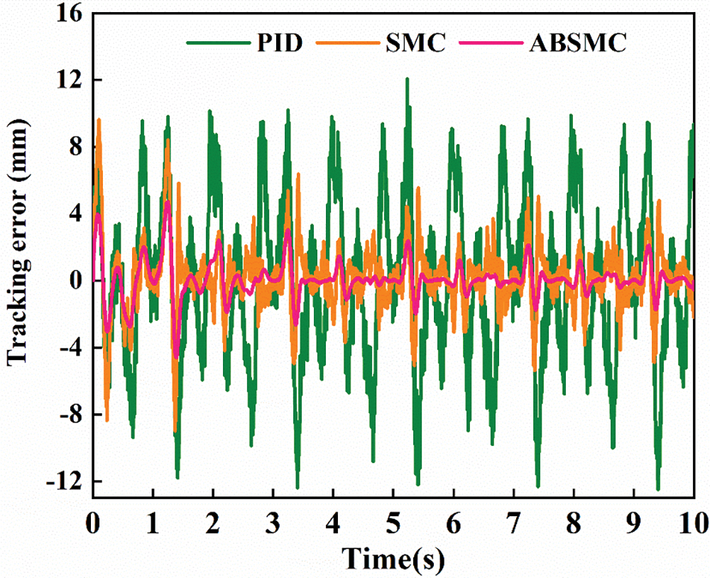
Figure 10: Tracking error of multifrequency-sinusoidal motion
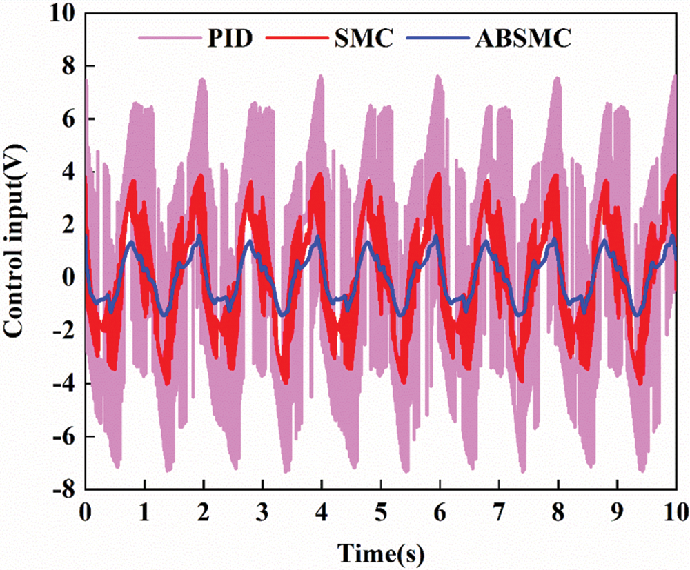
Figure 11: Control input of multifrequency-sinusoidal motion
The results of trajectory tracking and tracking error of quasi-sinusoidal motion y = 30 arctan(sin(20πt)) [1−exp(−6t)] are shown in Figs. 12 and 13, respectively. The trajectory tracking performance of ABSMC is, again, better than that of the other two controllers. In addition, PID and SMC have higher peak errors than the ABSMC when the actuator changes its direction. The corresponding performance indices of quasi-sinusoidal motion are listed in Table 4. The ABSMC performs better than the classical PID and SMC of its adaptive control law. Although the SMC also uses the sliding theory, its tracking performance is worse than that of the SMC. This verifies the superiority of the adaptive law in the ABSMC controller.
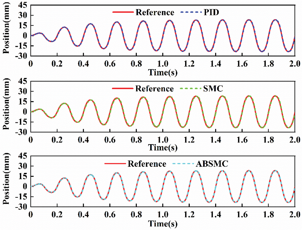
Figure 12: Tracking trajectory of quasi-sinusoidal motion

Figure 13: Tracking error of quasi-sinusoidal motion
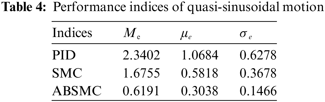
Fig. 14 shows the comparison results of stochastic signal with an amplitude of 5 m/s2 and frequency of 1–30 Hz. The tracking precision of the acceleration response under the PID controller is relatively poor. Although SMC improves the accuracy of the acceleration waveform, the tracking effect is not improved. After the ABSMC is adopted, the precision of waveform reproduction is enhanced, and the reference acceleration signal is tracked well. The acceleration response under the EI Centro seismic signal is shown in Fig. 15. The tracking performance of SMC is better than that of PID controller, while the tracking performance of ABSMC is better than that of SMC. That is to say, the acceleration response based on ABSMC has better tracking accuracy than PID and SMC for random and seismic signals.

Figure 14: Tracking trajectory of stochastic acceleration motion

Figure 15: Tracking trajectory of seismic acceleration motion
Fig. 16 compares the performance indices result of three controllers for the stochastic and seismic signal. It indicates that ABSMC achieves better performance than PID and SMC. The SMC greatly improves the tracking accuracy of the reference acceleration signal, and the Me under stochastic signal and seismic signal decreases by 40.43% and 23.49%, respectively. The Me, μe, and σe under the SMC are smaller than the PID because the SMC can handle the unmodeled disturbances and uncertainties to some extent under challenging working conditions. The σe of the stochastic signal reduces from 0.8012 to 0.2059, and the seismic signal from 0.6512 to 0.2153, confirming the importance of parameters adaption law.
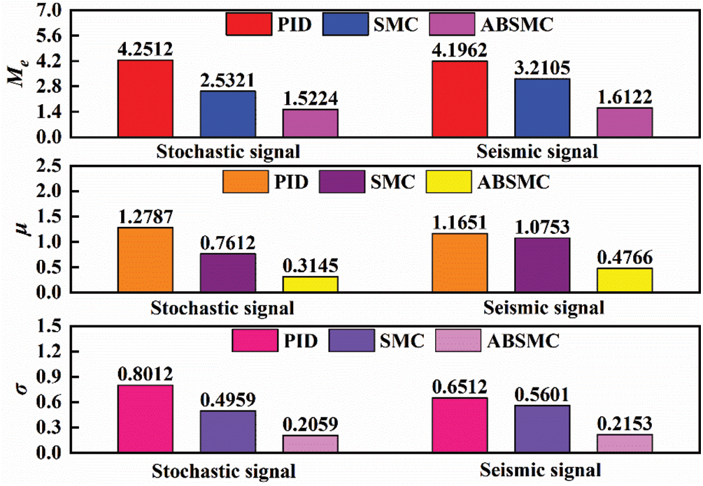
Figure 16: Comparison performance indices result of three controllers
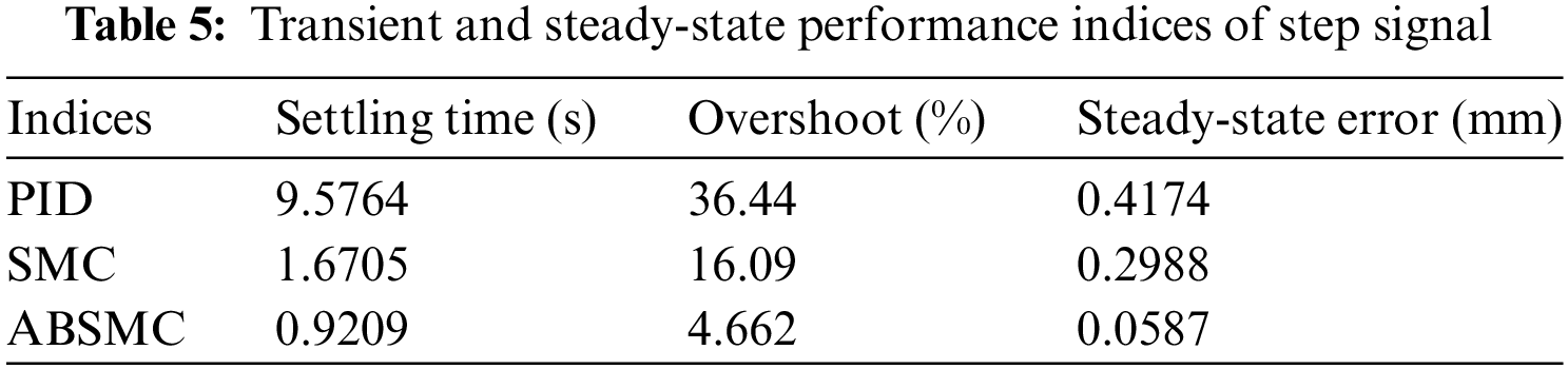
The tracking trajectory of the step signal for three controllers is shown in Fig. 17. Large fluctuations occur in the initial stage of the PID, while the initial stage of SMC and ABSMC shows smooth tracking. The transient and steady-state performance indices of the step signal are listed in Table 5. ABSMC produces the highest tracking performance, and PID generates the worst tracking performance. The overshoot under step signal is reduced to 4.662% of ABSMC controller, down from 36.44% of PID controller. The steady-state error of the ABSMC controller is only 20% of that of the SMC controller, which illustrates the effectiveness of the adaptive control law. All results demonstrate that the developed ABSMC controller performs better than the other controllers.
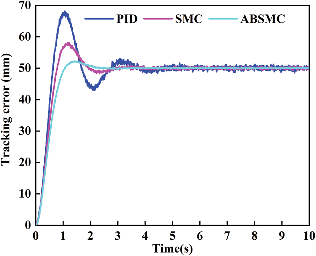
Figure 17: Tracking trajectory of step signal
This study develops an ABSMC for hydraulic actuators with high-precision trajectory tracking control subjected to model uncertainties and disturbances. It first establishes the hydraulic actuator dynamic model and derives the corresponding state-space equation. Next, the ABSMC is designed to improve the system’s robustness, where the adaptive law is employed to estimate unknown uncertainties. Finally, comparative experimental results verify the effectiveness of the proposed control scheme. Complex working conditions in the controller design will be considered for future work, such as hydraulic actuators with input saturation and state constraints. The limitation of this study is that the controller performance under different degrees of model uncertainty and dynamic interference is not further investigated.
Acknowledgement: The authors wish to thank their colleagues for their suggestions to improve the quality of this article.
Funding Statement: The work is supported by the fund of Henan Key Laboratory of Superhard Abrasives and Grinding Equipment, Henan University of Technology (Grant No. JDKFJJ2023005), the Key Science and Technology Program of Henan Province (Grant Nos. 242102221001 and 232102220085), the Science and Technology Key Project Foundation of Henan Provincial Education Department (Grant No. 23A460014).
Author Contributions: The authors confirm their contribution to the paper as follows: study conception and design: Zhenshuai Wan, Longwang Yue; system analysis and modeling: Zhenshuai Wan, Pu Zhao; controller and observer design: Zhenshuai Wan; platform construction and experimental design: Zhenshuai Wan; Yanfeng Wang; analysis and interpretation of results: Zhenshuai Wan, Yanfeng Wang; draft manuscript preparation: Zhenshuai Wan, Yanfeng Wang. All authors reviewed the results and approved the final version of the manuscript.
Availability of Data and Materials: The datasets generated and/or analyzed during this study are available from the corresponding author upon reasonable request.
Ethics Approval: Not applicable.
Conflicts of Interest: The authors have no conflicts of interest that could potentially influence the integrity, objectivity, or impartiality of the research presented in this article.
References
1. Zhang J, Liu J, Ding F. Collaborative optimization design framework for hierarchical filter barrier control suspension system with projection adaptive tracking hydraulic actuator. Nonlin Dynam. 2022;108(4):3417–34. doi:10.1007/s11071-022-07374-x. [Google Scholar] [CrossRef]
2. Guo Q, Chen ZL. Neural adaptive control of single-rod electrohydraulic system with lumped uncertainty. Mech Syst Signal Pr. 2021;146(2):106869. doi:10.1016/j.ymssp.2020.106869. [Google Scholar] [CrossRef]
3. Yuan S, Deng W, Liang X, Yao J, Yang G. Nonlinear robust adaptive precision motion control of motor servo systems with unknown actuator backlash compensation. ISA Trans. 2023;137(1):349–57. doi:10.1016/j.isatra.2023.02.002. [Google Scholar] [PubMed] [CrossRef]
4. Na J, Wang SB, Liu YJ, Huang YB, Ren XM. Finite-time convergence adaptive neural network control for nonlinear servo systems. IEEE Trans Cybern. 2020;50(6):2568–79. doi:10.1109/TCYB.2019.2893317. [Google Scholar] [PubMed] [CrossRef]
5. Wang SB, Na J, Ren XM, Yu HS, Yu JP. Unknown input observer-based robust adaptive funnel motion control for nonlinear servomechanisms. Int J Robust Nonlin. 2018;28(18):6163–79. doi:10.1002/rnc.4368. [Google Scholar] [CrossRef]
6. Van M, Do XP, Mavrovouniotis M. Self-tuning fuzzy PID-nonsingular fast terminal sliding mode control for robust fault tolerant control of robot manipulators. ISA Trans. 2020;96(4):60–8. doi:10.1016/j.isatra.2019.06.017. [Google Scholar] [PubMed] [CrossRef]
7. Guo Q, Li XC, Zuo ZY, Shi Y, Jiang D. Quasi-synchronization control of multiple electrohydraulic actuators with load disturbance and uncertain parameters. IEEE/ASME Trans Mechatron. 2021;26(4):2048–58. doi:10.1109/TMECH.2020.3030032. [Google Scholar] [CrossRef]
8. Yang XB, Zheng XL, Chen YH. Position tracking control law for an electro-hydraulic servo system based on back-stepping and extended differentiator. IEEE/ASME Trans Mechatron. 2018;23(1):132–40. doi:10.1109/TMECH.2017.2746142. [Google Scholar] [CrossRef]
9. Jing CH, Xu HG, Jiang JH. Dynamic surface disturbance rejection control for electro-hydraulic load simulator. Mech Syst Signal Pr. 2019;134:106293. doi:10.1016/j.ymssp.2019.106293. [Google Scholar] [CrossRef]
10. Liu L, Zhao W, Liu YJ, Tong S, Wang YY. Adaptive finite-time neural network control of nonlinear systems with multiple objective constraints and application to electromechanical system. IEEE Trans Neur Net Lear. 2021;32(12):5416–26. doi:10.1109/TNNLS.2020.3027689. [Google Scholar] [PubMed] [CrossRef]
11. Na J, Ren XM, Herrmann G, Qiao Z. Adaptive neural dynamic surface control for servo systems with unknown dead-zone. Control Eng Pract. 2011;19(11):1328–43. doi:10.1016/j.conengprac.2011.07.005. [Google Scholar] [CrossRef]
12. Niu B, Duan P, Li J, Li X. Adaptive neural tracking control scheme of switched stochastic nonlinear pure-feedback nonlower triangular systems. IEEE Trans Syst Man Cybern: Syst. 2021;51(2):975–86. doi:10.1109/TSMC.2019.2894745. [Google Scholar] [CrossRef]
13. Qiao L, Zhang WD. Trajectory tracking control of AUVs via adaptive fast nonsingular integral terminal sliding mode control. IEEE Trans Ind Inform. 2020;16(2):1248–58. doi:10.1109/TII.2019.2949007. [Google Scholar] [CrossRef]
14. Jin M, Kang SH, Chang PH, Lee J. Robust control of robot manipulators using inclusive and enhanced time delay control. IEEE-ASME Trans Mech. 2017;22(5):2141–52. doi:10.1109/TMECH.2017.2718108. [Google Scholar] [CrossRef]
15. Kim BS, Yoo SJ. Approximation-based adaptive tracking control of nonlinear pure-feedback systems with time-varying output constraints. INT J Control Autom. 2015;13(2):257–65. doi:10.1007/s12555-014-0084-6. [Google Scholar] [CrossRef]
16. Yan S, Sun WC, He FH, Yao JY. Adaptive fault detection and isolation for active suspension systems with model uncertainties. IEEE Trans Reliab. 2019;68(3):927–37. doi:10.1109/TR.2018.2868949. [Google Scholar] [CrossRef]
17. Liu W, Lim C-C, Shi P, Xu S. Back-stepping fuzzy adaptive control for a class of quantized nonlinear systems. IEEE Trans Fuzzy Syst. 2017;25(5):1090–101. doi:10.1109/TFUZZ.2016.2598360. [Google Scholar] [CrossRef]
18. Huang YB, Na J, Wu X, Gao GB. Approximation-free control for vehicle active suspensions with hydraulic actuator. IEEE Trans Ind Electron. 2018;65(9):7258–67. doi:10.1109/TIE.2018.2798564. [Google Scholar] [CrossRef]
19. Razzaghian A, Moghaddam RK, Pariz N. Fractional-order nonsingular terminal sliding mode control via a disturbance observer for a class of nonlinear systems with mismatched disturbances. J Vib Control. 2021;27(1–2):140–51. doi:10.1177/1077546320925263. [Google Scholar] [CrossRef]
20. Xu N, Liu X, Li Y, Zong G, Zhao X, Wang H. Dynamic event-triggered control for a class of uncertain strict-feedback systems via an improved adaptive neural networks back-stepping approach. IEEE Trans Autom Sci Eng. 2024;1–10. doi:10.1109/TASE.2024.3374522. [Google Scholar] [CrossRef]
21. Zhang MJ, Liu X, Yin BJ, Liu WX. Adaptive terminal sliding mode based thruster fault tolerant control for underwater vehicle in time-varying ocean currents. J Frank Inst. 2015;352(11):4935–61. doi:10.1016/j.jfranklin.2015.08.009. [Google Scholar] [CrossRef]
22. Li C, Chen Z, Yao B. Identification and adaptive robust precision motion control of systems with nonlinear friction. Nonlin Dynam. 2019;95(2):995–1007. doi:10.1007/s11071-018-4610-6. [Google Scholar] [CrossRef]
23. Essa MEM, Aboelela MAS, Hassan MAM, Abdrabbo SM. Model predictive force control of hardware implementation for electro-hydraulic servo system. Trans Inst Meas Control. 2019;41(5):1435–46. doi:10.1177/0142331218784118. [Google Scholar] [CrossRef]
24. Zhao H, Zhao N, Zong G, Zhao X, Xu N. Sliding-mode surface-based approximate optimal control for nonlinear multiplayer Stackelberg-Nash games via adaptive dynamic programming. Commun Nonlin Sci. 2024;132(7):107928. doi:10.1016/j.cnsns.2024.107928. [Google Scholar] [CrossRef]
25. Guo K, Li M, Shi W, Pan Y. Adaptive tracking control of hydraulic systems with improved parameter convergence. IEEE Trans Ind Electron. 2022;69(7):7140–50. doi:10.1109/TIE.2021.3101006. [Google Scholar] [CrossRef]
26. Guo Q, Zhang Y, Celler BG, Su SW. Back-stepping control of electro-hydraulic system based on extended-state-observer with plant dynamics largely unknown. IEEE Trans Ind Electron. 2016;63(11):6909–20. doi:10.1109/TIE.2016.2585080. [Google Scholar] [CrossRef]
27. Cheng C, Liu SY, Wu HZ. Sliding mode observer-based fractional-order proportional-integral-derivative sliding mode control for electro-hydraulic servo systems. Proc Inst Mech Eng Part C: J Mech Eng Sci. 2020;234(10):1887–98. doi:10.1177/0954406220903337. [Google Scholar] [CrossRef]
28. Zhuang HX, Sun QL, Chen ZQ, Jiang YX. Back-stepping sliding mode control for pressure regulation of oxygen mask based on an extended state observer. Automatica. 2020;119(9):109106. doi:10.1016/j.automatica.2020.109106. [Google Scholar] [CrossRef]
29. Chen Z, Guo Q, Li T, Yan Y, Jiang D. Gait prediction and variable admittance control for lower limb exoskeleton with measurement delay and extended-state-observer. IEEE Trans Neur Net Lear. 2022;34(11):1–14. [Google Scholar]
30. Asl RM, Hagh YS, Anavatti S, Handroos H. Adaptive finite integral non-singular terminal synergetic control of nth-order nonlinear systems. Mech Syst Signal Pr. 2020;142(5):106789. doi:10.1016/j.ymssp.2020.106789. [Google Scholar] [CrossRef]
31. Zhao J, Na J, Gao GB. Robust tracking control of uncertain nonlinear systems with adaptive dynamic programming. Neurocomputing. 2022;471(6):21–30. doi:10.1016/j.neucom.2021.10.081. [Google Scholar] [CrossRef]
32. Yang CG, Jiang YM, He W, Na J, Li ZJ, Xu B. Adaptive parameter estimation and control design for robot manipulators with finite-time convergence. IEEE Trans Ind Electron. 2018;65(10):8112–23. doi:10.1109/TIE.2018.2803773. [Google Scholar] [CrossRef]
33. Palli G, Strano S, Terzo M. Sliding-mode observers for state and disturbance estimation in electro-hydraulic systems. Control Eng Pract. 2018;74(9):58–70. doi:10.1016/j.conengprac.2018.02.007. [Google Scholar] [CrossRef]
34. Park JH, Kim SH, Park TS. Output-feedback adaptive neural controller for uncertain pure-feedback nonlinear systems using a high-order sliding mode observer. IEEE Trans Neur Net Lear. 2019;30(5):1596–601. doi:10.1109/TNNLS.2018.2861942. [Google Scholar] [PubMed] [CrossRef]
35. Xin C, Li YX, Ahn CK. Adaptive neural asymptotic tracking of uncertain non-strict feedback systems with full-state constraints via command filtered technique. IEEE Trans Neur Net Lear. 2022;34(10):1–6. [Google Scholar]
Cite This Article
 Copyright © 2024 The Author(s). Published by Tech Science Press.
This work is licensed under a Creative Commons Attribution 4.0 International License , which permits unrestricted use, distribution, and reproduction in any medium, provided the original work is properly cited.
 Downloads
 Citation Tools