
 Submit a Paper
 Propose a Special lssue
 Open Access
ARTICLE
A Mathematical Modeling of 3D Cubical Geometry Hypothetical Reservoir under the Effect of Nanoparticles Flow Rate, Porosity, and Relative Permeability
1 Department of Fundamental and Applied Sciences, Universiti Teknologi PETRONAS, Bandar Seri Iskandar, 32610, Malaysia
2 School of Mathematics, Actuarial and Quantitative Studies (SOMAQS), Asia Pacific University of Technology and Innovation (APU), Kuala Lumpur, 57000, Malaysia
3 Center for Research in Enhanced Oil Recovery, Universiti Teknologi PETRONAS, Bandar Seri Iskandar, 32610, Malaysia
4 Department of Physical and Mathematical Sciences, Faculty of Science, Universiti Tunku Abdul Rahman, Perak, 31900, Malaysia
5 Laboratory on Convective Heat and Mass Transfer, Tomsk State University, Tomsk, 634050, Russia
6 Department of Mathematical Sciences, Faculty of Science & Technology, Universiti Kebangsaan Malaysia, Bangi, 43600, Malaysia
7 Henan Province International Collaboration Lab of Forest Resources Utilization, School of Forestry, Henan Agricultural University, Zhengzhou, 450002, China
8 Higher Institution Centre of Excellence (HICoE), Institute of Tropical Aquaculture and Fisheries (AKUATROP), Universiti Malaysia Terengganu, Kuala Nerus, 21030, Malaysia
* Corresponding Author: Mudasar Zafar. Email:
(This article belongs to the Special Issue: Numerical Modeling and Simulations on Non-Newtonian Flow Problems)
Computer Modeling in Engineering & Sciences 2024, 141(2), 1193-1211. https://doi.org/10.32604/cmes.2024.049259
Received 01 January 2024; Accepted 13 May 2024; Issue published 27 September 2024
 View Full Text
 Download PDF
Abstract
This study aims to formulate a steady-state mathematical model for a three-dimensional permeable enclosure (cavity) to determine the oil extraction rate using three distinct nanoparticles, SiO2, Al2O3, and Fe2O3, in unconventional oil reservoirs. The simulation is conducted for different parameters of volume fractions, porosities, and mass flow rates to determine the optimal oil recovery. The impact of nanoparticles on relative permeability ( and water is also investigated. The simulation process utilizes the finite volume ANSYS Fluent. The study results showed that when the mass flow rate at the inlet is low, oil recovery goes up. In addition, they indicated that silicon nanoparticles are better at getting oil out of the ground (i.e., oil reservoir) than Al2O3 and Fe2O3. Most oil can be extracted from SiO2, Al2O3, and Fe2O3 at a rate of 97.8%, 96.5%, and 88%, respectively.Keywords
Nomenclature
| Bc | Nanofluid pressure term |
| D | Capillary diffusion |
| k | Nanofluid permeability |
| Pore throat blocking | |
| Surface retention rate of nanoparticles | |
| p | Initial pressure |
| R | Retention quantity for nanofluid |
| S | Saturation inside the reservoir |
| t | Time for nanoflooding |
| u | Speed of the nanofluid flow inside cavity |
| VF | Volume fraction of nanofluids |
| Greek Letters | |
| Bulk surface area | |
| Laplacian operator | |
| Nanoparticle densityin reservoir | |
| Nanofluids viscosity in the cavity | |
| Parameter for the porosity term | |
| Concentration parameter for nanofluid | |
| Volumetric parameter for nanoparticles inside the cavity | |
| Nanofluid velocity inside cubical cavity | |
| Porous medium surface area parameter | |
| Subscript | |
| abs | Symbol to use absolute term |
| c | Symbol to indicate capillary pressure |
| d | Symbol for identify diffusion term |
| e | Symbol to recognize effectiveness |
| g | Symbol to calculate rock diameter |
| o | Symbol for oil |
| p | Symbol to calculate nanoparticle diameter |
| ro | Identification of oil residual |
| rw | Identification of water residual |
| rw, p | Relative permeability of water inside nanoparticles |
| rw, o | Relative permeability of water inside nanofluid |
| w | Water term inside the cavity |
Despite the growing interest in renewable energy, crude oil remains essential for meeting global energy demands. However, there are challenges in the current oil extraction methods, highlighting the need for innovative technologies and solutions in the coming years.
Oil recovery from reservoirs usually involves three main stages: initial recovery, intermediate recovery, and tertiary or enhanced oil recovery (EOR) [1]. About 35% to 50% of the oil is retrieved during the primary and secondary recovery. The remaining 50% to 65% requires EOR for extraction [2].
The oil industry faces challenges in maximizing oil extraction from reservoirs. Conventional EOR includes thermal recovery, chemical flooding, and miscible flooding. Thermal recovery involves heating the oil to reduce its viscosity, which is costly and environmentally harmful [3,4]. In chemical flooding, surfactant, polymer, or alkaline solutions are injected into the reservoir to enhance oil extraction [5,6]. However, due to the complex geometry of oil reservoirs, injecting these solutions into wells is challenging as they can raise temperatures and disrupt the environment. As a result, implementing this technique on a large scale is hindered [7,8].
Miscible flooding involves mixing gases with crude oil under pressure to maximize oil extraction. However, maintaining high pressure in reservoirs of 610 to 1,524 m deep is challenging. Additionally, during high-viscosity oil displacement, gas emergence and channeling are problematic. Given these limitations, developing new technology for reliable, cost-effective, and environmentally friendly maximum oil recovery from reservoirs remains a significant challenge for the petroleum industry [5].
Nanotechnology is widely utilized across various industries, including the oil and gas sector. It offers numerous benefits and applications within this industry. Nanoparticles and nanofluids are particularly valuable as they are being utilized in drilling, which enhances production, prevents mitigating formation impairment, boosts oil retrieval, improves heat exchange efficiency, treats wastewater, and aids the mobilization of viscous oils both on surfaces and within reservoirs [6,7]. Traditional methods of oil retrieval and reservoir pressure alone can only recover approximately one-third of the entire oil reservoir’s resources. EOR methods are critical to extract a larger volume of oil [8]. Conventional oil-based recovery methods and reservoir pressure can only extract about one-third of the total oil resources from hydrocarbon reservoirs. EOR techniques are required to recover more oil. Several studies, especially those focusing on nanoparticle use in EOR processes, have demonstrated a significant increase in oil recovery rates [9–13].
Nanoparticles have been used in real-world projects. A major obstacle encountered in these applications was the unexpected increase in viscosity experienced by base fluids after dispersing nanoparticles [10,14,15]. A previous study has investigated the impact of nanoparticle size on the thermal conductivity and dynamic viscosity of
On the other hand, nanoparticles made of silica, A
This study aims to develop a model that explains the behavior of nanofluids in porous media. Typically, there are two approaches to understanding how nanoparticles travel through porous materials. The Lagrangian method involves tracking particles along the flow path, while the Eulerian method solves the mass equation for the particles. In this method, a filtration term is incorporated into the advection-dispersion equation to determine the movement and retention of nanoparticles over time [27].
The following section outlines the governing equations utilized to simulate the nanoflooding process for EOR using three distinct nanoparticles. Understanding these partial differential equation systems and their application in nanofluid injection is crucial for maximizing oil recovery. This study employs nanofluids to mimic the flooding process, which is a method for enhancing oil recovery from reservoirs.
The research is conducted within a three-dimensional cubic cavity, employing the finite volume method for numerical analysis. This method yields superior results compared to existing literature, and the use of a cubic cavity assumption is novel in this context. The simulation investigates the effects of three different nanoparticles: silica, aluminum, and iron oxide. By leveraging the model proposed by [28], the study analyzes the impact of porosity, nanoparticle volume fraction, and permeability on porous media and oil recovery factors.
The following sections present the basic assumptions of the model aiming to find the optimal oil extraction in a cubical cavity by investigating three different nanoparticles: silica, aluminum, and iron oxide. Following this, the mathematical equations utilized to develop the model are clarified, and their significance in predicting the oil recovery rate is discussed. Lastly, the methodology for constructing the geometry for the simulations is explained, including details about input and output tools, physical properties, and other essential simulation parameters.
The following hypotheses are considered to introduce the system of equations that govern the nanoflooding process and extract the high amount of oil from the reservoir:
Nanofluid injection in the geometry is one-dimensional. In the hypothetical reservoir, it is assumed that the rock is clean and contains sandstones. Nanofluid flow inside the cubical cavity is non-compressible. The flooding process is governed by the Darcy Law. The chemical reaction between the nanoparticles is neglected, and thermal equilibrium is maintained between the nanoparticles. The problem obeys Newton’s law, and the gravitational effect is not considered. The appropriate simulation procedure and the outcome are fully reliable even through the eight approximations, as validated through prior experimental research. The consistency between the numerical results and experimental work demonstrates that the assumptions made to develop the current model have no detrimental effects on the precision and veracity of the results.
This section provides a concise explanation of the governing equations, including the Darcy equations, saturation equations, and nanoparticle transport equations. Additionally, it discusses the framework and mathematical relations involving porosity, absolute permeability, and equations of permeability. These equations will be numerically solved using Ansys’ Fluent Finite Volume Method (FVM) solver to achieve maximum oil recovery in a cubical cavity comprising a porous medium. In this model, a simulation is run for seven different pore volumes to predict the oil recovery rate in the cubical cavity.
This paper presents a mathematical model for nanofluid injection involving a system of partial differential equations (PDEs) to optimize the oil recovery rate within a simulated 3D porous cubical cavity representing reservoir rock. Depending on the specific scenario, inertial terms may be incorporated into the Naiver-Stokes equations to neglect gravitational forces. Due to the steady flow observed in porous media within reservoirs, the Darcy equations are utilized to model the flow [12].
where
where
Eqs. (2) and (3) will be used to solve the Darcy equation to obtain velocity and pressure values. The saturation equation is solved using these values. The next subsection explains the saturation equation. The sum of the saturation of oil and water is taken as one. It is also worth mentioning that the viscosity of oil and water emulsion is higher than that of a simple mixture.
The steady-state saturation is defined as [28]
The values of the fluid’s diffusion into the surrounding fluid play a crucial role from the perspective of the equation that defines saturation. Generally, this value is determined using the Eq. (6).
where
Moreover, it can be evaluated by [29] and mathematically represented in Eq. (7).
Where
where
2.2.3 Nanoparticles Transport Equations
Regulating the application of nanofluids and managing the concentration of nanoparticles within them is essential. While nanoparticles can have a positive effect, uncontrolled usage may diminish efficiency even more than water flooding [30–34]. High-temperature nanofluids enhance oil recovery by facilitating faster heat transfer, reducing oil viscosity, and increasing oil outflow from the reservoir. Nanoparticles also boost water density and energy, raising fluid pressure and Brownian motion for increased oil release. Nevertheless, unregulated nanoparticle utilization may diminish efficiency. The oil industry primarily employs two types of nanoparticles for enhanced oil recovery. The first type comprises lipophobic and hydrophilic nanoparticles (LHPN), dispersing solely in the water phase. In contrast, the second type comprises hydrophobic and lipophilic nanoparticles (HLPN), dispersing exclusively in the oil phase. This study focused on investigating LHPN to streamline the issue. Consequently, nanoparticles may exist either in the aqueous phase or on the rock surface. For each phase of flow, the following equation is utilized to figure out how nanoparticles move through the porous medium [19,35].
where
The mathematical quantities
2.2.4 Equations for Porosity & Absolute Permeability
The porosity can be calculated using the following equation:
In the flooding process, absolute permeability is also affected when nanoparticles block the pore throat, and it can be calculated as
By using Eqs. (12) and (13), the permeability can be calculated as follows:
2.2.5 Equation for Relative Permeability
In the EOR two-phase injection of nanofluids flow, the relation between relative permeability is evaluated using [38].
where the terms
The values of
Relative permeability, being a dimensionless ratio, does not possess a specific SI unit, and its values range between 0 and 1.
2.3 Construction of the Cavity for Oil Reservoir Simulation
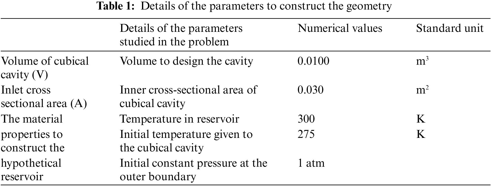
In this section, the construction of the three-phase cubical cavity using nanofluid injection with initial and boundary conditions for improved oil recovery rate is discussed. Three different kinds of nanoparticles (i.e., SiO2, Al2O3, and Fe2O3) are injected from the inlet with water to find out the recovery factor. The block diagram of the geometry, along with the I.C. (initial condition) and B.C. (boundary conditions) is shown in Fig. 1. The parameters to construct the geometries are in Table 1.
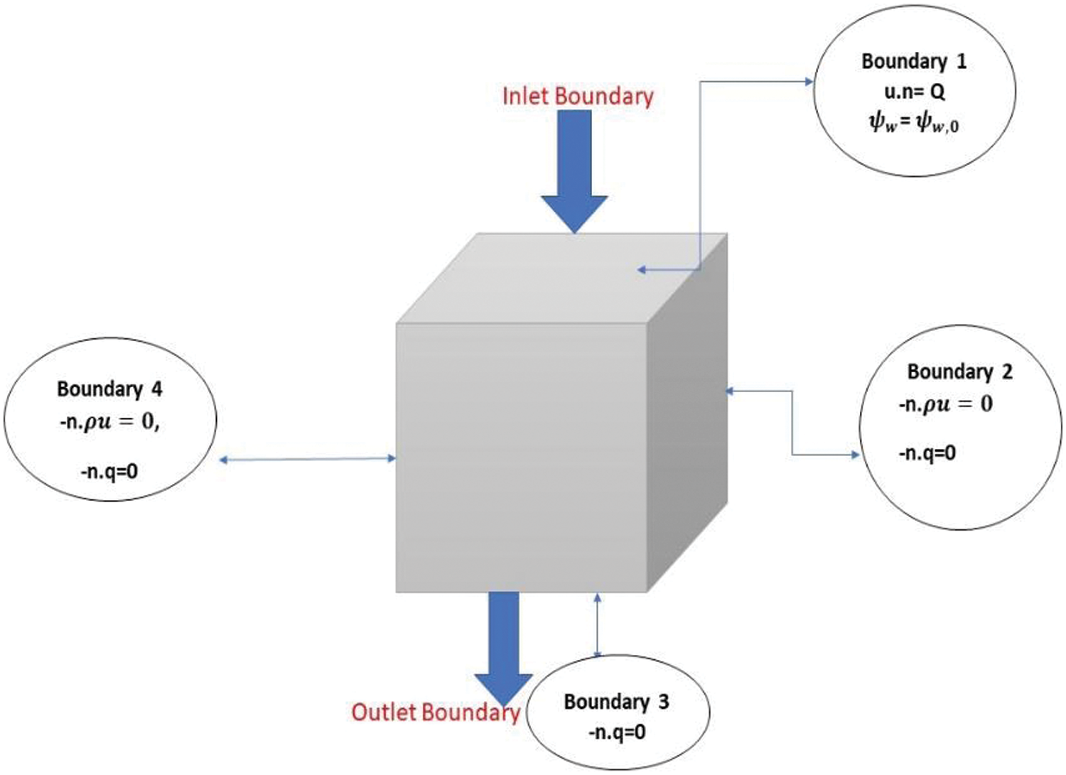
Figure 1: Cubical geometry used for simulation
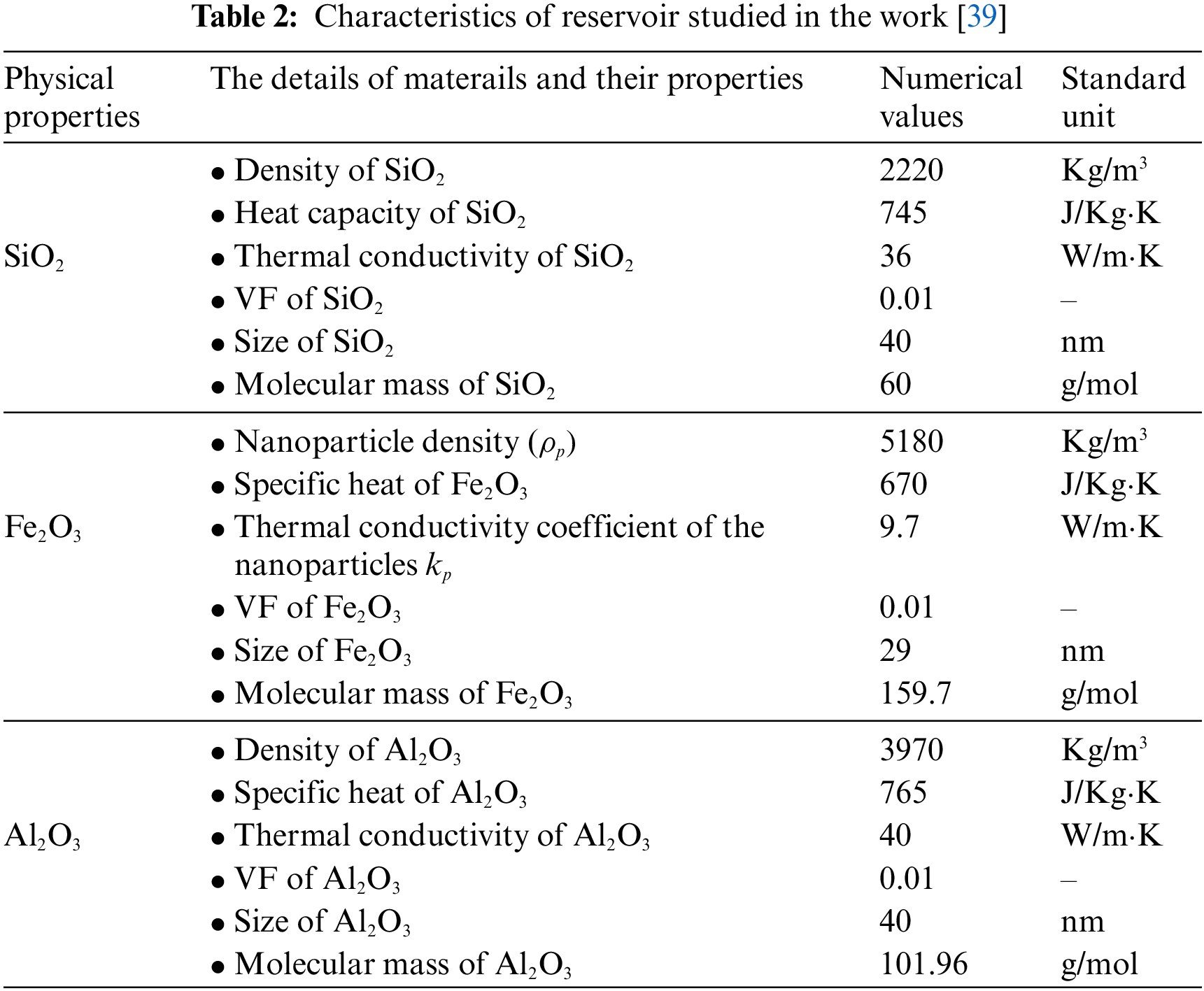
The material and physical properties of nanoparticles, oil and water, and reservoir rock are also described in Table 2, which is utilized to investigate the model.
2.3.1 Initial and Boundary Conditions
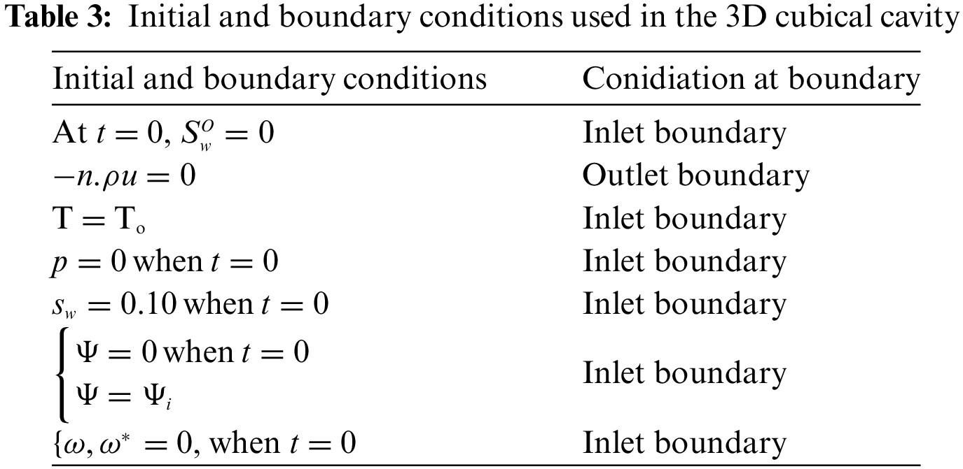
In this problem, the domain is divided into four boundaries. The boundary where the flooding process begins is referred to as boundary 1 or the inlet boundary. The boundary where fluid exits, or the outlet boundary, is denoted as boundary 4. Boundaries 2 and 3 are assumed to have no fluid entering or exiting. The details of the boundary conditions used in this problem are shown in Table 3.
3 Methodology and Verification of the Model
The FVM method is employed to solve the two-phase steady-state model, calculating the oil recovery factor within a cubical geometry. This mathematical framework comprises interconnected nonlinear PDEs for reservoir simulation that were analyzed using the Ansys Fluent tool. A mesh independence test is conducted in this study. Furthermore, the model is verified using experimental data to ensure accuracy. The following section provides a detailed overview of the verification process and mesh analysis.
3.1 Mesh Independency Analysis
The model is solved using distinct grids to evaluate oil recovery factors across different time spans. The results for all grids are presented in Table 4.
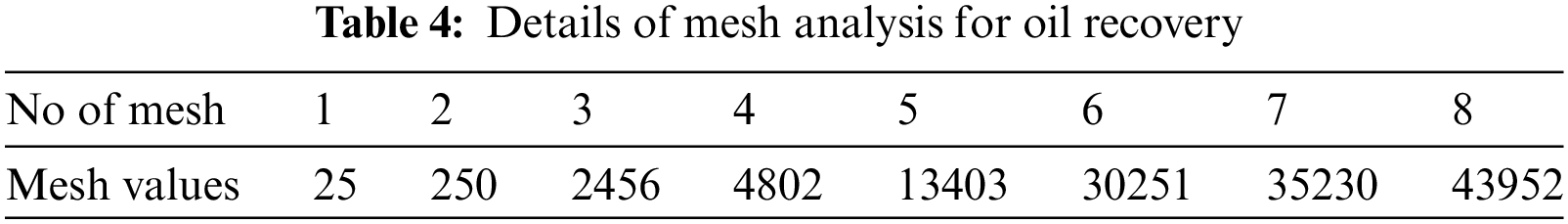
Fig. 2 displays the findings of the grid’s dependence on the geometry. As observed, grids 6, 7, and 8 exhibit considerable similarity to each other. This suggests that the model is insensitive to variations in mesh size. The conclusion is that grid number 6, which contains 30,251 nodes, is the ideal mesh to utilize for the flooding technique.
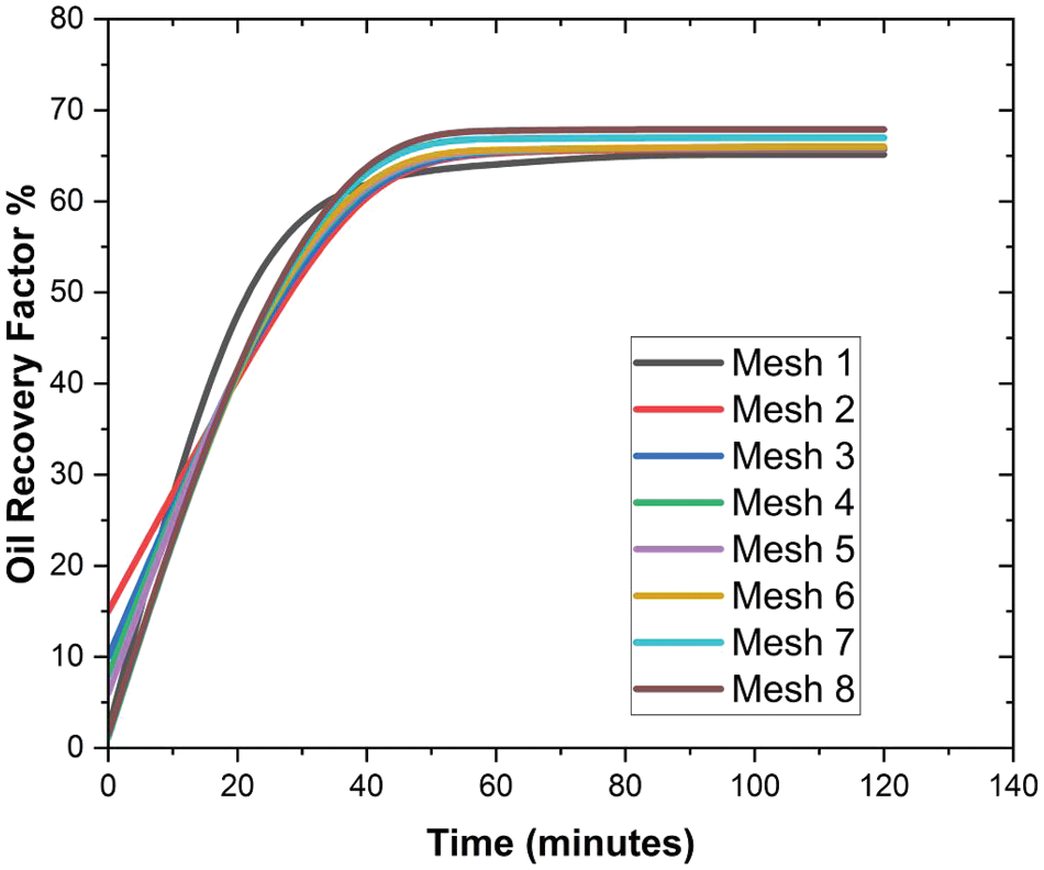
Figure 2: Grid Independency analysis
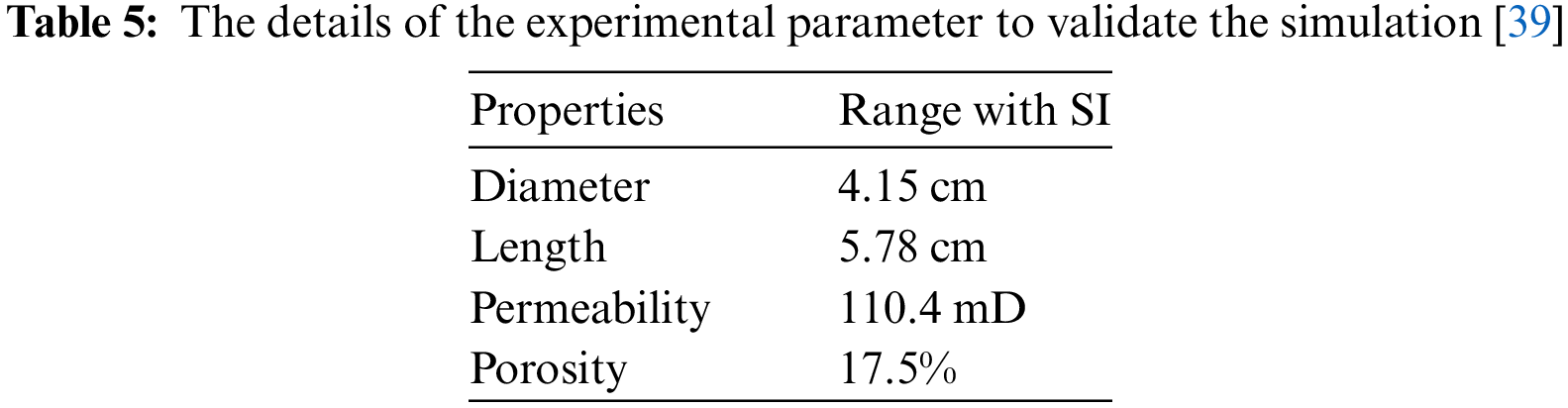
In order to ascertain the accuracy of the model, the outcomes are compared to data obtained from experimental investigation [39]. Nanoparticles of SiO2, Al2O3, and Fe2O3 were used in this study to help get more oil out of a porous cubic cavity. Table 5 shows the rock core properties and parameters used in the experimentation. SiO2 values from the experiment were taken to perform the validations.
A graph comparing experimental results and modeling is shown in Fig. 3.
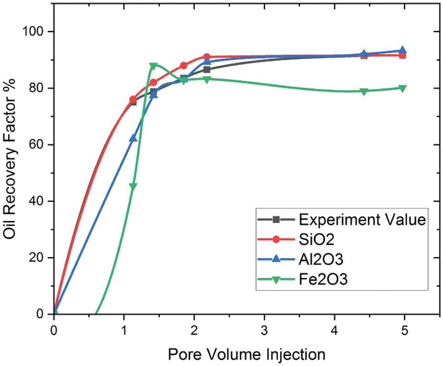
Figure 3: Validations of the study
The results of the experiment and the models match quite well, as seen in Fig. 3. After the model is made, it is used to simulate the nanofluid flooding process and study how the impact of various parameters on the recoverable oil volume within the cubic cavity.
In order to examine the influence of escalating the nanofluid flow rate within the medium, the disparity in saturation and oil recovery from the medium was contrasted at three distinct flow rates: 0.05, 0.03, and 0.02 mL/min, as illustrated in Fig. 4. These flow rates were chosen to explore the impact of the nanofluid flow rate on injection.
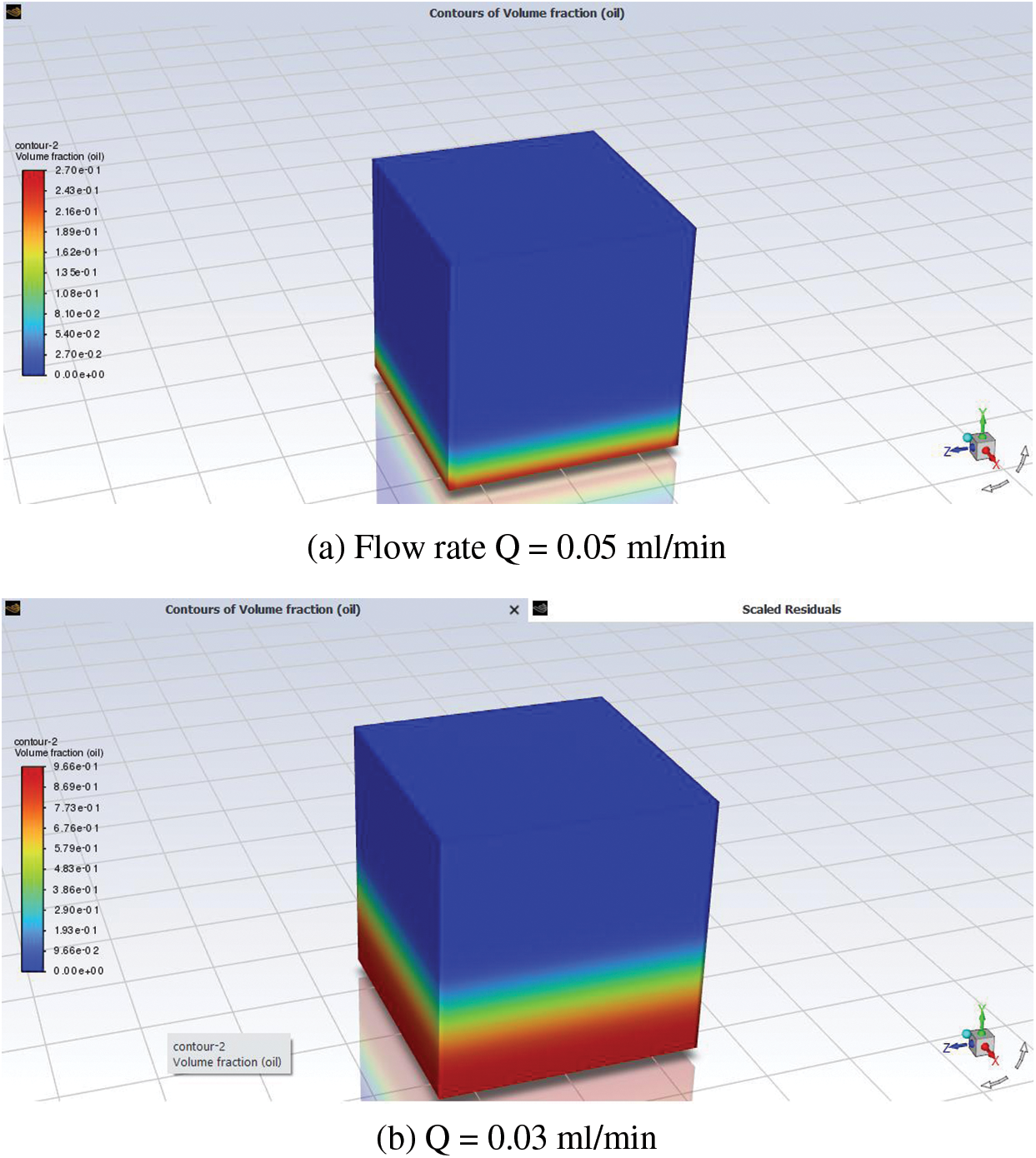
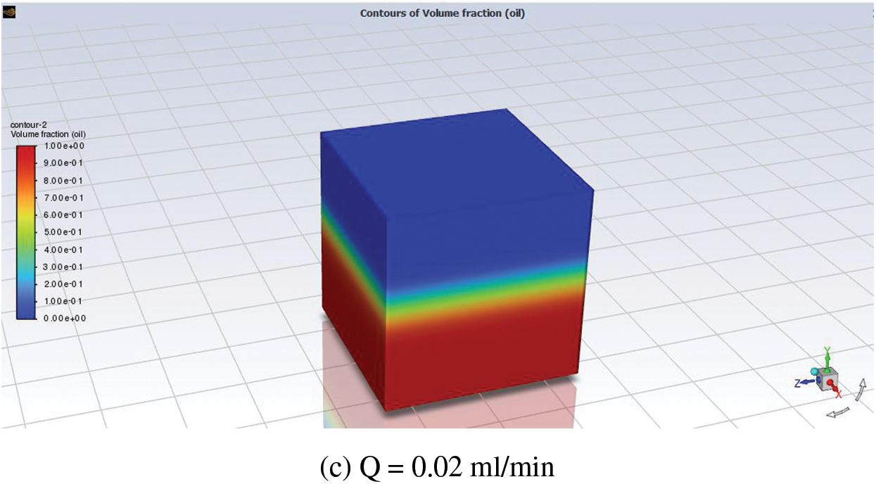
Figure 4: Ct flow rates: (a) Q = 0.05 mL/min; (b) Q = 0.03 mL/min; (c) Q = 0.02 mL/min
Fig. 4 illustrates the correlation that occurs between the saturation and flow rate for each of the three distinct mass flow rates. According to these saturation distribution profiles, when the flow was lowered from 0.05 to 0.02 mL/min, less water was put into the medium, which caused the oil in the medium to be replaced by water. Fig. 5 depicts the change in the oil recovery profile because of pore volume injection.
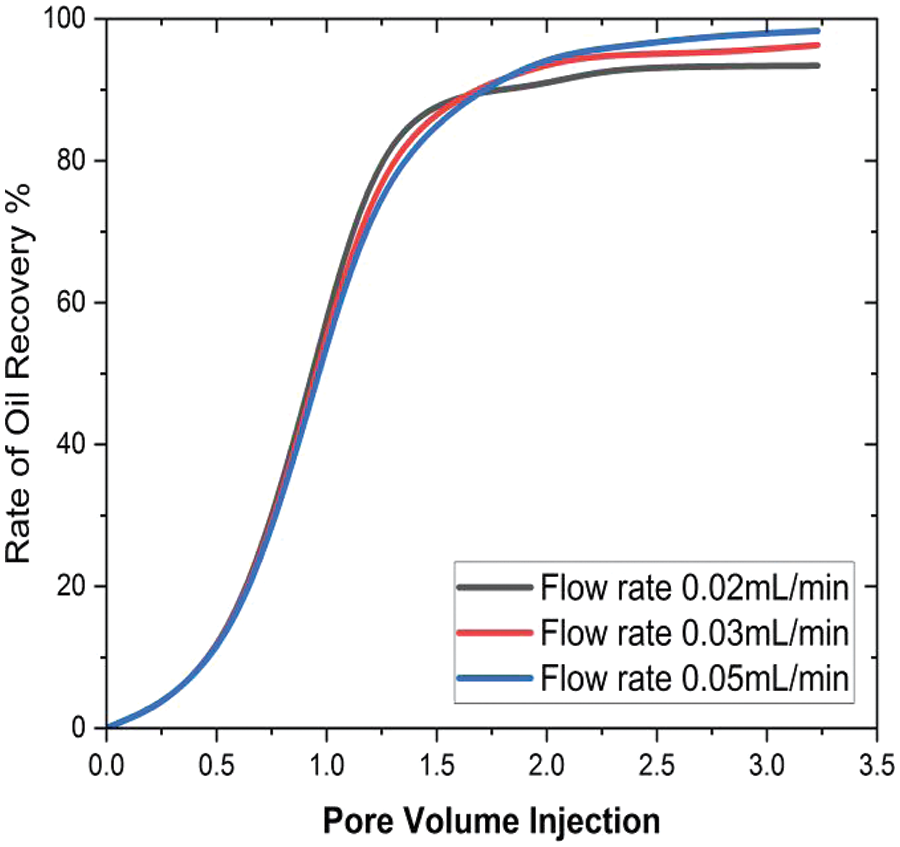
Figure 5: Effect of inlet flow rate on oil recovery
Fig. 5 shows that initially, the oil recovery rate is very slow in the pore volumes, but at pore volume 1.3, the oil recovery reaches 90% for flow rates of 0.02 mL/min, 93.3% for flow rates of 0.03 mL/min, and 94.2% for flow rates of 0.05 mL/min. This trend gradually intensifies with increasing pore volumes. For flow rates of 0.02 and 0.03 mL/min, the maximum oil recovery factor by the final pore volume is 96%, while at an inlet flow rate of 0.05 mL/min, 98% of the oil is recovered. Thus, it’s apparent that lower inlet flow rates yield higher oil recovery. This phenomenon can be attributed to the prolonged contact time resulting from decreased flow rates, leading to enhanced molecular interaction and subsequently increased oil recovery. Similar observations have been reported by the authors [40,41].
The saturation and oil recovery factor during nanofluid injection with nanoparticles (volume fraction of 0.01) were compared for three different core porosity values, 0.1, 0.25, and 0.4, to investigate the impact of porosity on the results. Figs. 6 and 7 illustrate the effect of the porosity when SiO2 is injected into the reservoir.
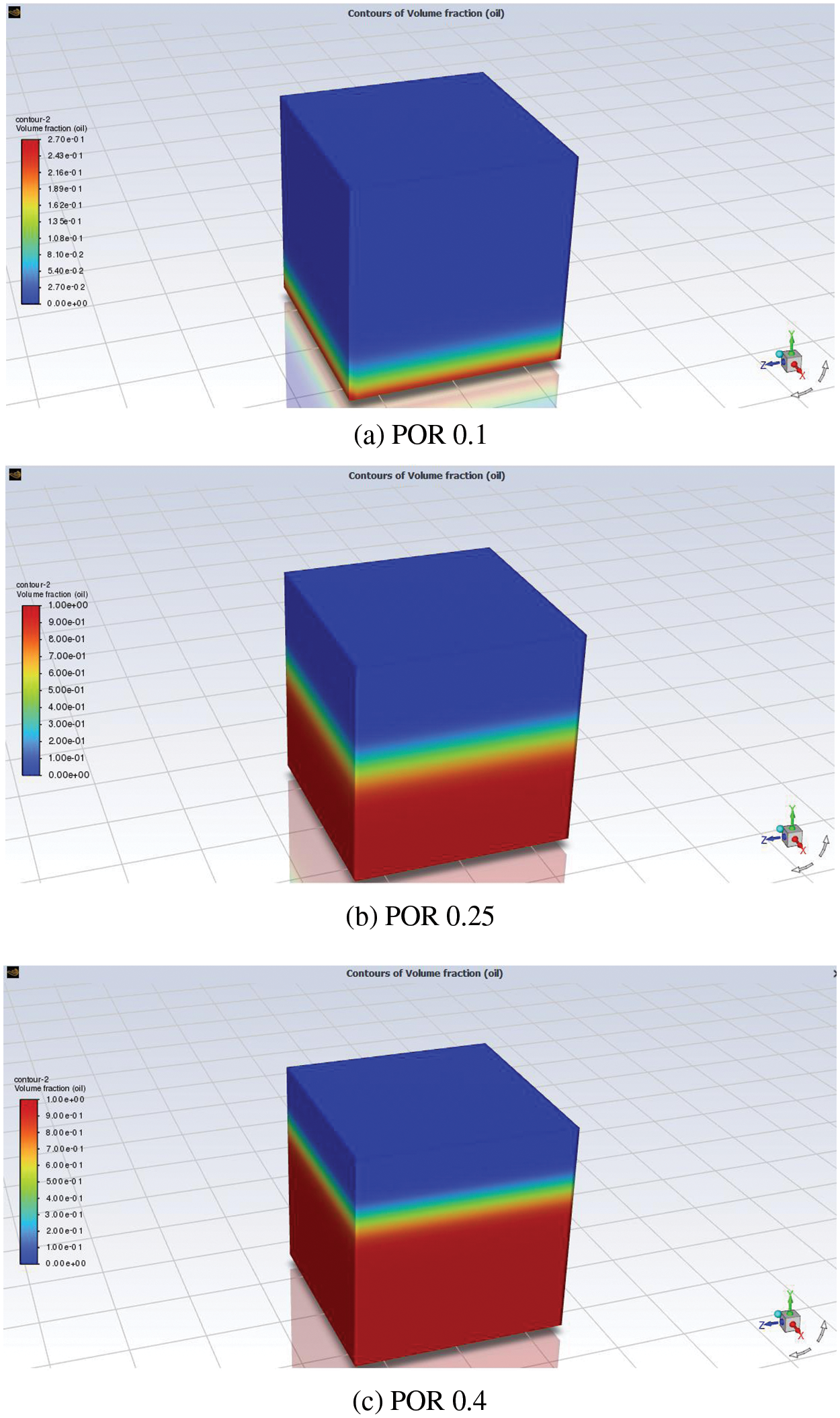
Figure 6: Effect of porosity on oil recovery factor: (a) POR 0.1; (b) POR 0.25; (c) POR 0.4
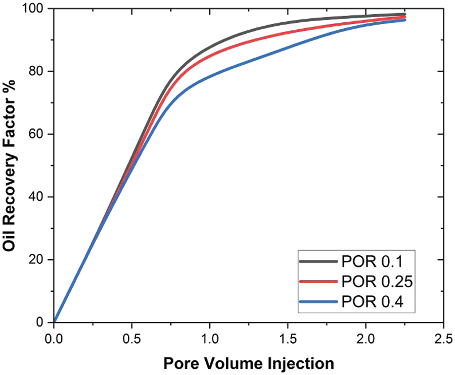
Figure 7: Effect of the porosity on oil recovery factor
A comparison of the porous volume injection and oil recovery factor at three different pore sizes is shown in Fig. 7. In this study, the effect of three distinct porosity values is examined in a seven-pore volume in order to examine oil recovery in the cubical cavity. The same oil recovery factor is obtained at the first three pore volumes. However, after these, a higher amount of oil is extracted from 0.1, and at 0.4, the oil recovery rate is somewhat lower than the other values. Additionally, it is found that a pore size of 0.1 results in 98.23% oil recovery, a pore size of 0.25 results in 97.3% oil recovery, and a pore size of 0.4 results in 96.34% oil recovery. It is observed that the oil recovery at low porosity values increases, which is due to the formation of the cubical cavity, allowing more fluid to pass when its parameter is lesser. This, as a result, allows the nanofluids to recover more oil.
The effect of permeability on oil recovery for silicon, aluminum oxide, and iron oxide is shown in Fig. 8.
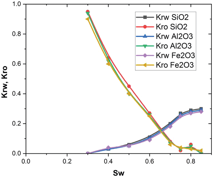
Figure 8: Relative permeability behavior at three different nanoparticles
The relative permeability of the two fluids is a crucial factor to consider in EOR and the resolution of two-phase flows. In the current investigation, the addition of nanoparticles to the water led to a modification in the relative permeability of oil and water fluids. The primary drivers for EOR can be observed in Fig. 8, indicating that the enhancement of nanofluid relative permeability, coupled with the reduction in oil permeability due to nanoparticle presence, were the underlying mechanisms behind EOR. This process led to an enhancement in water relative permeability, consequently improving oil flow. In summary, the utilization of nanofluids rather than water significantly enhanced the performance of the EOR process. The same finding was also reported in previous studies [40–43]. The influence of silicon, aluminum oxide, and iron oxide in a three-dimensional cubical cavity is explored in this research under the parameters of a nanoparticle volume fraction ranging from 0.01–0.05. The graph that displays the relationship between pore volume injection and oil recovery factor can be found in Figs. 9–11. By examining five various volume fractions, the influence that the nanoparticles have on the oil recovery factor is explained in these figures.
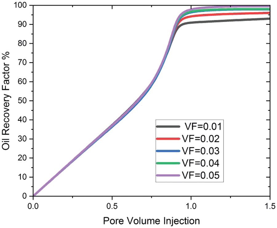
Figure 9: Effect of SiO2VF on oil recovery
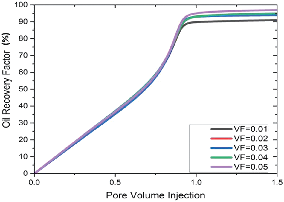
Figure 10: Effect of Al2O3VF on oil recovery
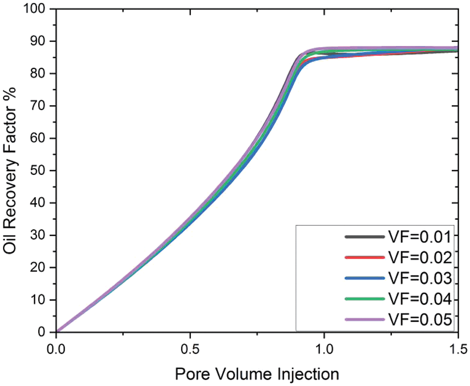
Figure 11: Effect of Fe2O3VF on oil recovery factor
Fig. 9 exhibits the additional oil recovery achieved with silicon nanoparticles in seven different pore volumes. The maximum oil recovery during the nanoflooding process is 91% at VF = 0.01% and 94.5% at VF = 0.02; 96% at VF = 0.03; 97.5% at VF = 0.04; 97.8% at VF = 0.05.
Fig. 10 shows how much extra oil can be recovered with nanoparticles of aluminum in seven different pore volumes. During the nanoflooding process, the most oil can be recovered when VF = 0.01; 93.5% when VF = 0.02; 94.5% when VF = 0.03; 95.5% when VF = 0.04; and 96.8% when VF = 0.05.
Fig. 11 shows how much extra oil can be recovered with nanoparticles of iron in seven different pore volumes. During the nanoflooding process, the most oil can be recovered when VF = 0.01; 80% when VF = 0.02; 79.5% when VF = 0.03; 82.91% when VF = 0.04; and 88.8% when VF = 0.05. During the simulation process of oil recovery prediction in the cubical cavity when iron oxide is inserted, the oil recovery attained is lowest as compared to the other nanoparticles at each parameter of VF due to the fact that the oil recovery in iron oxide is less as compared to silica and aluminum nanoparticles. As depicted in Figs. 9–11, an elevation in the total nanoparticle concentration correlates with an augmentation in the oil recovery factor. This observation may stem from the fact that augmenting the volume percentage of nanoparticles causes an escalation in nanofluid viscosity and density, subsequently mitigating the fingering effect. The same pattern of findings was also discovered in some other studies [39]. Fig. 12 shows the comparisons of the oil recovery factor obtained from nanoparticles with water flooding.
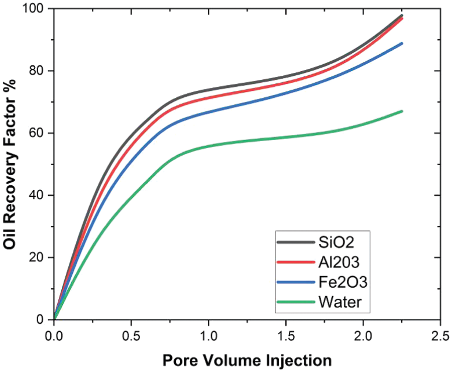
Figure 12: Comparison of oil recovery from nanoparticles with water
The intention of this study is to develop a model for cubical geometry in order to maximize optimal oil recovery. In this simulation, the effect of three distinct nanoparticles, namely silica, aluminum, and iron oxide, was examined. The following are the conclusions for this paper based on the findings:
• The recovery coefficient and EOR efficiency depend on reservoir porosity. It is found that a pore size of 0.1 results in 98.23% oil recovery, a pore size of 0.25 results in 97.3% oil recovery, and a pore size of 0.4 results in 96.34% oil recovery.
• It has been found that silicon nanoparticles provide maximum oil recovery compared to Al2O3 and Fe2O3. Most of the oil can be extracted from SiO2 at a rate of 97.8%, from Al2O3 at 96.5%, and from Fe2O3 at 88%.
• It is also observed that nanomaterials have a positive impact on the relative permeability of the oil and water, which increases the EOR process.
At flow rates of 0.02 and 0.03 mL/min, the maximum oil recovery factor for the last pore volume is 96%, while 98% of the oil is recovered at inlet flow rates of 0.05 mL/min. Therefore, it is evident that lower inlet flow rates result in higher oil recovery. This phenomenon occurs because a decrease in flow rate leads to an increase in contact time, facilitating enhanced molecular interaction and consequently boosting oil recovery.
Acknowledgement: The author thanks the Department of Fundamental and Applied Science at the University Teknologi PETRONAS (UTP) for their support and assistance.
Funding Statement: The APC of this article is covered by Research Grant YUTP 015LCO-526.
Author Contributions: Study and conception design; Mudasar Zafar, Iskandar Dzulkarnain, Abida Hussain, analysis and result interpretation; Mudasar Zafar, Hamzah Sakidin, Roslinda Nazar, Mikhail Sheremet, Abdullah Al-Yaari; draft manuscript: Mudasar Zafar, Abida Hussain, Loshini Thiruchelvam, Rizwan Safdar. All authors reviewed the results and approved the final version of the manuscript.
Availability of Data and Materials: All data is provided in this paper.
Conflicts of Interest: The authors declare that they have no conflicts of interest to report regarding the present study.
References
1. Sheng JJ. Modern chemical enhanced oil recovery: theory and practice. Houston, USA: Gulf Professional Publishing; 2010 Nov 25. [Google Scholar]
2. Green DW, Willhite GP. Enhanced oil recovery. Richardson, USA: Society of Petroleum Engineers; 1998. [Google Scholar]
3. Wu Z, Sun Z, Shu K, Jiang S, Gou Q, Chen Z. Mechanism of shale oil displacement by CO2 in nanopores: a molecular dynamics simulation study. Advances in Geo-Energy Research. 2024 Feb 1;11(2):141–51. [Google Scholar]
4. Wu ZB, Liu HQ, Wang X. Adaptability research of thermal-chemical assisted steam injection in heavy oil reservoirs. J Energy Resour Technol. 2018 May 1;140(5):052901. [Google Scholar]
5. Kumar N, Sampaio MA, Ojha K, Hoteit H, Mandal A. Fundamental aspects, mechanisms and emerging possibilities of CO2 miscible flooding in enhanced oil recovery: a review. Fuel. 2022 Dec 15;330:125633. [Google Scholar]
6. Bera A, Belhaj H. Application of nanotechnology by means of nanoparticles and nanodispersions in oil recovery–A comprehensive review. J Nat Gas Sci Eng. 2016 Aug 1;34:1284–309. [Google Scholar]
7. Liu Y, Liu C, Li Y, Xu Y, Han Y, Pu W, et al. Experimental study of an amphiphilic graphene oxide based nanofluid for chemical enhanced oil recovery of heavy oil. New J Chem. 2023;47(4):1945–53. [Google Scholar]
8. Fletcher AJ, Davis JP. How EOR can be transformed by nanotechnology. In: SPE Improved Oil Recovery Symposium; 2010 Apr 24; Tulsa, Oklahoma, USA. p. SPE-129531. [Google Scholar]
9. Esfe MH, Hosseinizadeh E, Esfandeh S. Flooding numerical simulation of heterogeneous oil reservoir using different nanoscale colloidal solutions. J Mol Liq. 2020 Mar 15;302(10):111972. doi:10.1016/j.molliq.2019.111972. [Google Scholar] [CrossRef]
10. Esfe MH, Esfandeh S. 3D numerical simulation of the enhanced oil recovery process using nanoscale colloidal solution flooding. J Mol Liq. 2020 Mar 1;301(9):112094. doi:10.1016/j.molliq.2019.112094. [Google Scholar] [CrossRef]
11. Zafar M, Sakidin H, Sheremet M, Dzulkarnain IB, Hussain A, Nazar R, et al. Recent development and future prospective of tiwari and das mathematical model in nanofluid flow for different geometries: a review. Processes. 2023 Mar 10;11(3):834. doi:10.3390/pr11030834. [Google Scholar] [CrossRef]
12. Zafar M, Sakidin H, Dzulkarnain I, Hussain A, Sheremet M, Nazar R, et al. The impact of 3D prism cavity for enhanced oil recovery using different nanomaterials. Materials. 2023 May 27;16(11):4011. doi:10.3390/ma16114011. [Google Scholar] [PubMed] [CrossRef]
13. Zafar M, Sakidin H, Sheremet M, Dzulkarnain I, Nazar R, Al-Yaari A, et al. A numerical investigation of mathematical modelling in 3D hexagonal porous prism on oil recovery using nanoflooding. Heliyon. 2023 Aug 1;9(8):e18676. doi:10.1016/j.heliyon.2023.e18676. [Google Scholar] [PubMed] [CrossRef]
14. Esfe MH, Esfandeh S. Effect of capillary pressure parameter and volume fraction of nanoparticles on EOR process in a 3D geometry. Int Commun Heat Mass Transf. 2022 Feb 1;131(3):105762. doi:10.1016/j.icheatmasstransfer.2021.105762. [Google Scholar] [CrossRef]
15. Rebello LR, Nicolini JV, Ferraz HC. Nanofluid formulation based on the combined effect of silica nanoparticles and low salinity water for Enhanced Oil Recovery in sandstones. Geoenergy Sci Eng. 2023 Apr 1;223:211570. [Google Scholar]
16. Hemmat Esfe M, Saedodin S, Wongwises S, Toghraie D. An experimental study on the effect of diameter on thermal conductivity and dynamic viscosity of Fe/water nanofluids. J Therm Anal Calorim. 2015 Mar;119(3):1817–24. doi:10.1007/s10973-014-4328-8. [Google Scholar] [CrossRef]
17. Esfe MH, Arani AA, Rezaie M, Yan WM, Karimipour A. Experimental determination of thermal conductivity and dynamic viscosity of Ag-MgO/water hybrid nanofluid. Int Commun Heat Mass Transf. 2015 Aug 1;66(2):189–95. doi:10.1016/j.icheatmasstransfer.2015.06.003. [Google Scholar] [CrossRef]
18. Ju B, Fan T. Experimental study and mathematical model of nanoparticle transport in porous media. Powder Technol. 2009 Jun 5;192(2):195–202. doi:10.1016/j.powtec.2008.12.017. [Google Scholar] [CrossRef]
19. El-Amin MF, Kou J, Sun S, Salama A. Numerical modeling of nanoparticles transport with two-phase flow in porous media using iterative implicit method. arXiv preprint arXiv:1310.4769. 2013 Oct 17. [Google Scholar]
20. AfzaliTabar M, Alaei M, Khojasteh RR, Motiee F, Rashidi AM. Preference of multi-walled carbon nanotube (MWCNT) to single-walled carbon nanotube (SWCNT) and activated carbon for preparing silica nanohybrid pickering emulsion for chemical enhanced oil recovery (C-EOR). J Solid State Chem. 2017 Jan 1;245:164–73. [Google Scholar]
21. Abiz MR, Norouzi-Apourvari S, Jafari S, Schaffie M. The effect of subsurface factors on the performance of nanofluid-assisted enhanced oil recovery: modeling and sensitivity analysis. J Pet Sci Eng. 2021 Jul 1;202:108553. [Google Scholar]
22. Adil M, Lee K, Mohd Zaid H, Ahmad Latiff NR, Alnarabiji MS. Experimental study on electromagnetic-assisted ZnO nanofluid flooding for enhanced oil recovery (EOR). PLoS One. 2018 Feb 28;13(2):e0193518. [Google Scholar]
23. Chandio TA, Manan MA, Memon KR, Abbas G, Abbasi GR. Enhanced oil recovery by hydrophilic silica nanofluid: experimental evaluation of the impact of parameters and mechanisms on recovery potential. Energies. 2021 Sep 13;14(18):5767. [Google Scholar]
24. Youssif MI, El-Maghraby RM, Saleh SM, Elgibaly A. Silica nanofluid flooding for enhanced oil recovery in sandstone rocks. Egypt J Pet. 2018 Mar 1;27(1):105–10. [Google Scholar]
25. Zafar M, Sakidin H, Dzulkarnain I, Afzal F. Numerical investigations of nano-fluid flow in square porous cavity: buongiorno’s mathematical model. In: Proceedings of the 6th International Conference on Fundamental and Applied Sciences: ICFAS 2020; 2021; Singapore: Springer. p. 739–48. [Google Scholar]
26. Mahmoudpour M, Pourafshary P. Investigation of the effect of engineered water/nanofluid hybrid injection on enhanced oil recovery mechanisms in carbonate reservoirs. J Pet Sci Eng. 2021 Jan 1;196:107662. [Google Scholar]
27. Salama A, Negara A, El Amin M, Sun S. Numerical investigation of nanoparticles transport in anisotropic porous media. J Contam Hydrol. 2015 Oct 1;181:114–30. [Google Scholar]
28. Raafat E, Soliman MM, Khattab HM. Improving heavy oil recovery by nanofluid injection: the factors affecting and mathematical modeling. J Petroleum Mining Eng. 2014;17(1):88–98. [Google Scholar]
29. Kjosavik A, Ringen JK, Skjaeveland SM. Relative permeability correlation for mixed-wet reservoirs. In: SPE Improved Oil Recovery Conference; 2000 Apr 3; SPE. p. SPE-59314. [Google Scholar]
30. Cheraghian G, Hendraningrat L. A review on applications of nanotechnology in the enhanced oil recovery part A: effects of nanoparticles on interfacial tension. Int Nano Lett. 2016 Jun;6:129–38. [Google Scholar]
31. Cheraghian G, Hendraningrat L. A review on applications of nanotechnology in the enhanced oil recovery part B: effects of nanoparticles on flooding. Int Nano Lett. 2016 Mar;6(1):1. [Google Scholar]
32. Sun Y, Yang D, Shi L, Wu H, Cao Y, He Y, et al. Properties of nanofluids and their applications in enhanced oil recovery: a comprehensive review. Energy & Fuels. 2020 Jan 19;34(2):1202–18. doi:10.1021/acs.energyfuels.9b03501. [Google Scholar] [CrossRef]
33. Li K, Wang D, Jiang S. Review on enhanced oil recovery by nanofluids. Oil & Gas Sci Technol-Revue d’IFP Energies Nouvelles. 2018;73(4):37. doi:10.2516/ogst/2018025. [Google Scholar] [CrossRef]
34. Panchal H, Patel H, Patel J, Shah M. A systematic review on nanotechnology in enhanced oil recovery. Petroleum Res. 2021 Sep 1;6(3):204–12. doi:10.1016/j.ptlrs.2021.03.003. [Google Scholar] [CrossRef]
35. Parker JC, Van Genuchten MT. Determining transport parameters from laboratory and field tracer experiments. 1984. doi:10.1520/STP29520S. [Google Scholar] [CrossRef]
36. Liu X, Civan F. Characterization and prediction of formation damage in two-phase flow systems (formation damage and filter cake in laboratory core tests-Part II: model assisted analaysis). In: SPE Oklahoma City Oil and Gas Symposium/Production and Operations Symposium; 1993 Mar 21; SPE. p. SPE-25429. [Google Scholar]
37. Gruesbeck C, Collins RE. Entrainment and deposition of fine particles in porous media. Soc Pet Eng J. 1982 Dec 1;22(6):847–56. doi:10.2118/8430-PA. [Google Scholar] [CrossRef]
38. Ju B, Fan T, Li Z. Improving water injectivity and enhancing oil recovery by wettability control using nanopowders. J Pet Sci Eng. 2012 May 1;86(11):206–16. doi:10.1016/j.petrol.2012.03.022. [Google Scholar] [CrossRef]
39. Joonaki E, Ghanaatian SJ. The application of nanofluids for enhanced oil recovery: effects on interfacial tension and coreflooding process. Pet Sci Technol. 2014 Nov 2;32(21):2599–607. [Google Scholar]
40. Feng Y, Cao L, Shi E. A numerical investigation of enhanced oil recovery using hydrophilic nanofluids. J Sustain Energy Eng. 2017 May 1;5(1):67–97. [Google Scholar]
41. Alnarabiji MS, Yahya N, Nadeem S, Adil M, Baig MK, Ghanem OB, et al. Nanofluid enhanced oil recovery using induced ZnO nanocrystals by electromagnetic energy: viscosity increment. Fuel. 2018 Dec 1;233:632–43. [Google Scholar]
42. Iyi D, Balogun Y, Oyeneyin B, Faisal N. A numerical study of the effects of temperature and injection velocity on oil-water relative permeability for enhanced oil recovery. Int J Heat Mass Transf. 2022 Aug 1;191:122863. [Google Scholar]
43. Parvazdavani M, Masihi M, Ghazanfari MH, Sherafati M, Mashayekhi L. Investigation of the effect of water based nano-particles addition on hysteresis of oil and-water relative permeability curves. In: SPE International Oilfield Nanotechnology Conference and Exhibition; 2012 Jun 12; SPE. p. SPE-157005. [Google Scholar]
Cite This Article
 Copyright © 2024 The Author(s). Published by Tech Science Press.
This work is licensed under a Creative Commons Attribution 4.0 International License , which permits unrestricted use, distribution, and reproduction in any medium, provided the original work is properly cited.
 Downloads
 Citation Tools